US1851706A - Electron discharge device - Google Patents
Electron discharge device Download PDFInfo
- Publication number
- US1851706A US1851706A US214199A US21419927A US1851706A US 1851706 A US1851706 A US 1851706A US 214199 A US214199 A US 214199A US 21419927 A US21419927 A US 21419927A US 1851706 A US1851706 A US 1851706A
- Authority
- US
- United States
- Prior art keywords
- anode
- grid
- light
- rod
- discharge device
- Prior art date
- Legal status (The legal status is an assumption and is not a legal conclusion. Google has not performed a legal analysis and makes no representation as to the accuracy of the status listed.)
- Expired - Lifetime
Links
- 239000010453 quartz Substances 0.000 description 11
- VYPSYNLAJGMNEJ-UHFFFAOYSA-N silicon dioxide Inorganic materials O=[Si]=O VYPSYNLAJGMNEJ-UHFFFAOYSA-N 0.000 description 11
- 229910052783 alkali metal Inorganic materials 0.000 description 6
- 150000001340 alkali metals Chemical class 0.000 description 6
- 229910052792 caesium Inorganic materials 0.000 description 4
- TVFDJXOCXUVLDH-UHFFFAOYSA-N caesium atom Chemical compound [Cs] TVFDJXOCXUVLDH-UHFFFAOYSA-N 0.000 description 4
- 239000011248 coating agent Substances 0.000 description 3
- 238000000576 coating method Methods 0.000 description 3
- QVQLCTNNEUAWMS-UHFFFAOYSA-N barium oxide Chemical compound [Ba]=O QVQLCTNNEUAWMS-UHFFFAOYSA-N 0.000 description 2
- 239000011521 glass Substances 0.000 description 2
- 229910052751 metal Inorganic materials 0.000 description 2
- 239000002184 metal Substances 0.000 description 2
- 239000005304 optical glass Substances 0.000 description 2
- 239000000126 substance Substances 0.000 description 2
- WFKWXMTUELFFGS-UHFFFAOYSA-N tungsten Chemical group [W] WFKWXMTUELFFGS-UHFFFAOYSA-N 0.000 description 2
- OYPRJOBELJOOCE-UHFFFAOYSA-N Calcium Chemical compound [Ca] OYPRJOBELJOOCE-UHFFFAOYSA-N 0.000 description 1
- FYYHWMGAXLPEAU-UHFFFAOYSA-N Magnesium Chemical compound [Mg] FYYHWMGAXLPEAU-UHFFFAOYSA-N 0.000 description 1
- NINIDFKCEFEMDL-UHFFFAOYSA-N Sulfur Chemical compound [S] NINIDFKCEFEMDL-UHFFFAOYSA-N 0.000 description 1
- 239000005864 Sulphur Substances 0.000 description 1
- 229910052791 calcium Inorganic materials 0.000 description 1
- 239000011575 calcium Substances 0.000 description 1
- 239000002775 capsule Substances 0.000 description 1
- 150000001875 compounds Chemical class 0.000 description 1
- 229910052749 magnesium Inorganic materials 0.000 description 1
- 239000011777 magnesium Substances 0.000 description 1
- 239000000463 material Substances 0.000 description 1
- KRTSDMXIXPKRQR-AATRIKPKSA-N monocrotophos Chemical compound CNC(=O)\C=C(/C)OP(=O)(OC)OC KRTSDMXIXPKRQR-AATRIKPKSA-N 0.000 description 1
- 239000007787 solid Substances 0.000 description 1
Images
Classifications
-
- H—ELECTRICITY
- H01—ELECTRIC ELEMENTS
- H01J—ELECTRIC DISCHARGE TUBES OR DISCHARGE LAMPS
- H01J40/00—Photoelectric discharge tubes not involving the ionisation of a gas
- H01J40/02—Details
- H01J40/04—Electrodes
Definitions
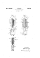
- Fig. 1 shows an elevation, partly broken away, of an electron discharge device embodying the features of the present invention
- Fig. 2 is an elevation partly broken.
- FIG. 3 is an elevation partly broken away of a modified form of cathode adapted to-be employed with the grid and anode disclosed in Fig. 1.
- the anode is supported upon aleading-in wire 5 extending through stem 6.
- the filamentary cathode 3 is concentrically disposed within the anode and connected to leading-in wires 7 and 8 which extend through the stem portion of the device.
- the grid or control electrode 4 as disclosed in Figs. 1 and 3 comprises a solid, helical, insulating member or rodmade of quartz or optical glass and having on its surface a monatomic coating or layer of caesium or other alkali metal which may be introduced into the tube from a metallic capsule 9 attached to the leading-in wire 5.
- the upper end of the quartz or glass rod 4 is fused to the container 1, as indicated at 10 in Fig. 1, and the lower end of the rod is fused to a metal. supporting rod 11 embedded in stem 6.
- the filament is preferably a tungsten wire coated with a monatomic film of caesium, though other forms of grid rod 4 traverses the rod from end to end.
- the light impinges internally on the quartz surface and is reflected therefrom, losing, however, but little of its. energy at each reflection, so thatmany reflections takeplace permitting thereby a large photoelectron emission from the surface of the grid4 with a; very weak beam of light.
- the quartz rod or grid when light is directed onto its end portion 10 gives up'photoelectrons to the plate or anode member 2 thereby becoming more positive. This action permits more current to fiow from the filament to the plate.
- the loss of electrons by the grid is balanced by electrons received from the filament, so that for each value of light intensity the grid assumes .a definite potential at which the number of electrons lost, due to the light, is just equal to the number received from the filament.
- a pair of filamentary electrodes 12 and 13 may be employed, as indicated in Fig. 3, the filament 13 being negative by a few volts with respect to filament 12 and operating at a much lower temperature.
- the purpose of filament 13 is to supply a small
- the sensitivene'ss of the device may be varied over a wide range.
- straight piece of quartz or optical glass rod 14 may be mounted concentrically within the anode 2, as shown in Fig- 2.
- the quartz rod is in this case supported on a stem 6 by means of a metal rod 15 embedded in the stem.
- the upper end 16 ofthe grid rod extends close to the inner surface of the container 1 and may, if desired, be fused thereto as in Fig. 1.
- the surface of the quartz rod is coated with a monatomic layer of caesium or other alkali metal.
- a filament 17 surrounds the quartz grid and is supplied with current through the leading-in wires 18 and 19. This filament may be of the thoriumcoated or of the Wehnelt type, but is preferably a caesium-coated tungsten wire, operating at a temperature between 800 K. and
- alkali metal coating on the grid other substances may be used, such as magnesium or calcium, which are sensitive only to ultraviolet light, or substances such as barium oxide or compounds of sulphur which are sensitive to infra red light.
- the amount of light directed onto the end of the quartz or glass grids will in each case determine or control the flow of current between the cathode and anode electrodes.
- An electron discharge device comprising a container, an anode, cathode and control electrode mounted in said container,said control electrode comprising a coiled vitreous member coated with alkali metal, one end of the coiled member being designed to' receive' light thereon to thereb control the current flow betweenthe catho e and anode.
- An electron dischargedevice comprising an anode, cathode and control electrode
- control electrode being interposed between the anode and cathode members-and comprising a vitreous member, elongate in dimension, and having a monatomic layer of alkali metal thereon, and means whereby light rays may be directed longitudinally through said member and may be caused to impinge on the alkali metal a plurality of times to thereby control the electron current flowing between the cathode and anode.
- An electron discharge device comprising an envelope containing an anode,-a cathode and control electrode, said control electrode comprising a quartz rod through which light may be transmitted longitudinally, said rod having thereon a coating of light-sensitive material which is activated b the transmitted light for controlling the e ectron current flowing between the anode and cathode members.
Landscapes
- Discharge Lamp (AREA)
- Vessels And Coating Films For Discharge Lamps (AREA)
- Discharge Lamps And Accessories Thereof (AREA)
Description
March 29, 1932. A,w.HuLL 1,851 706 ELECTRON .DI SCHARGE DEVI C E Filed Aug. 19. 192'! Inventor: Albert W. Hull,
Hls Attorneg.
Patented Mar. 29,- 1932 UNITED STATES PATENT OFFICE.
ALBERT W. HULL, OF SCHENECTAD Y, NEW YORK, ASSIGNOR TO GENERAL ELECTRIC COMPANY, .A CORPORATION OF NEW YORK nnnornon msonansn :onvron Application filed August 19, 192'}. Serial No. 214,199.
electrically insulated from the exterior of the discharge device.
The novel features which I believe to be characteristic of my invention are set forth with particularity in the appended claims.
The invention itself, however, will best be understood from reference to the following specification when, considered in connection with the accompanying drawings in which Fig. 1 shows an elevation, partly broken away, of an electron discharge device embodying the features of the present invention; Fig. 2 is an elevation partly broken.
away of a modified form of the invention; while Fig. 3 is an elevation partly broken away of a modified form of cathode adapted to-be employed with the grid and anode disclosed in Fig. 1.
Referring to the drawings, I have indicated at 1 an evacuated receptacle provided with a substantially cylindrical anode 2, a filamen tary cathode 3 and a control electrode or grid 4;. The anode is supported upon aleading-in wire 5 extending through stem 6. The filamentary cathode 3 is concentrically disposed within the anode and connected to leading-in wires 7 and 8 which extend through the stem portion of the device. The grid or control electrode 4 as disclosed in Figs. 1 and 3 comprises a solid, helical, insulating member or rodmade of quartz or optical glass and having on its surface a monatomic coating or layer of caesium or other alkali metal which may be introduced into the tube from a metallic capsule 9 attached to the leading-in wire 5. The upper end of the quartz or glass rod 4 is fused to the container 1, as indicated at 10 in Fig. 1, and the lower end of the rod is fused to a metal. supporting rod 11 embedded in stem 6. The filament is preferably a tungsten wire coated with a monatomic film of caesium, though other forms of grid rod 4 traverses the rod from end to end.
The light impinges internally on the quartz surface and is reflected therefrom, losing, however, but little of its. energy at each reflection, so thatmany reflections takeplace permitting thereby a large photoelectron emission from the surface of the grid4 with a; very weak beam of light.
The quartz rod or grid,when light is directed onto its end portion 10 gives up'photoelectrons to the plate or anode member 2 thereby becoming more positive. This action permits more current to fiow from the filament to the plate. The loss of electrons by the grid is balanced by electrons received from the filament, so that for each value of light intensity the grid assumes .a definite potential at which the number of electrons lost, due to the light, is just equal to the number received from the filament.
If desired, a pair of filamentary electrodes 12 and 13 may be employed, as indicated in Fig. 3, the filament 13 being negative by a few volts with respect to filament 12 and operating at a much lower temperature. The purpose of filament 13 is to supply a small,
temperature limited, balancing current of any desired magnitude, to the quartz grid. l.
In this way the sensitivene'ss of the device may be varied over a wide range.
Instead of the. helical form of grid, a
straight piece of quartz or optical glass rod 14 may be mounted concentrically within the anode 2, as shown in Fig- 2. The quartz rod is in this case supported on a stem 6 by means of a metal rod 15 embedded in the stem. The upper end 16 ofthe grid rod extends close to the inner surface of the container 1 and may, if desired, be fused thereto as in Fig. 1. The surface of the quartz rod is coated with a monatomic layer of caesium or other alkali metal. A filament 17 surrounds the quartz grid and is supplied with current through the leading-in wires 18 and 19. This filament may be of the thoriumcoated or of the Wehnelt type, but is preferably a caesium-coated tungsten wire, operating at a temperature between 800 K. and
Instead of the alkali metal coating on the grid other substances may be used, such as magnesium or calcium, which are sensitive only to ultraviolet light, or substances such as barium oxide or compounds of sulphur which are sensitive to infra red light.
The amount of light directed onto the end of the quartz or glass grids will in each case determine or control the flow of current between the cathode and anode electrodes.
WVhat I claim as new and desire to secure by Letters Patent of the United States is 1. An electron discharge device comprising a container, an anode, cathode and control electrode mounted in said container,said control electrode comprising a coiled vitreous member coated with alkali metal, one end of the coiled member being designed to' receive' light thereon to thereb control the current flow betweenthe catho e and anode.
2. An electron dischargedevice comprising an anode, cathode and control electrode,
, said control electrode being interposed between the anode and cathode members-and comprising a vitreous member, elongate in dimension, and having a monatomic layer of alkali metal thereon, and means whereby light rays may be directed longitudinally through said member and may be caused to impinge on the alkali metal a plurality of times to thereby control the electron current flowing between the cathode and anode.
3. An electron discharge device compris ing an envelope containing an anode,-a cathode and control electrode, said control electrode comprising a quartz rod through which light may be transmitted longitudinally, said rod having thereon a coating of light-sensitive material which is activated b the transmitted light for controlling the e ectron current flowing between the anode and cathode members. I I
In witness whereoj I have hereunto set my hand this 17th day of August, 1927.
ALBERT W. HULL.
Priority Applications (1)
| Application Number | Priority Date | Filing Date | Title |
|---|---|---|---|
| US214199A US1851706A (en) | 1927-08-19 | 1927-08-19 | Electron discharge device |
Applications Claiming Priority (1)
| Application Number | Priority Date | Filing Date | Title |
|---|---|---|---|
| US214199A US1851706A (en) | 1927-08-19 | 1927-08-19 | Electron discharge device |
Publications (1)
| Publication Number | Publication Date |
|---|---|
| US1851706A true US1851706A (en) | 1932-03-29 |
Family
ID=22798179
Family Applications (1)
| Application Number | Title | Priority Date | Filing Date |
|---|---|---|---|
| US214199A Expired - Lifetime US1851706A (en) | 1927-08-19 | 1927-08-19 | Electron discharge device |
Country Status (1)
| Country | Link |
|---|---|
| US (1) | US1851706A (en) |
Cited By (3)
| Publication number | Priority date | Publication date | Assignee | Title |
|---|---|---|---|---|
| US2449113A (en) * | 1944-07-22 | 1948-09-14 | Fruth Hal Frederick | Electric discharge device |
| US2506625A (en) * | 1946-07-08 | 1950-05-09 | Harold W Woolley | Photoelectric cell |
| US2553197A (en) * | 1941-06-25 | 1951-05-15 | Hartford Nat Bank & Trust Co | Photoelectric tube |
-
1927
- 1927-08-19 US US214199A patent/US1851706A/en not_active Expired - Lifetime
Cited By (3)
| Publication number | Priority date | Publication date | Assignee | Title |
|---|---|---|---|---|
| US2553197A (en) * | 1941-06-25 | 1951-05-15 | Hartford Nat Bank & Trust Co | Photoelectric tube |
| US2449113A (en) * | 1944-07-22 | 1948-09-14 | Fruth Hal Frederick | Electric discharge device |
| US2506625A (en) * | 1946-07-08 | 1950-05-09 | Harold W Woolley | Photoelectric cell |
Similar Documents
| Publication | Publication Date | Title |
|---|---|---|
| US3780331A (en) | Apparatus and method for eliminating microcracks in alumina ceramic discharge devices | |
| US2530990A (en) | Electric discharge device | |
| US2103041A (en) | Gaseous electric discharge lamp device | |
| GB499897A (en) | Improvements in auxiliary electrodes in electric discharge devices | |
| US2064369A (en) | Electric discharge tube | |
| US1851706A (en) | Electron discharge device | |
| US2200911A (en) | Sealed lead-in for cathode-ray tubes and the like | |
| US2084865A (en) | Light sensitive electron discharge device | |
| US1917739A (en) | Electric discharge device | |
| US1821808A (en) | Space discharge device | |
| US2056613A (en) | Electric gaseous discharge device | |
| US2430309A (en) | Electronic discharge device | |
| US3145318A (en) | Cathode grid assembly for electron gun | |
| US2381632A (en) | Electron discharge device | |
| US1880092A (en) | Electron discharge device | |
| US1899568A (en) | Cathode structure for vacuum tubes | |
| US2189636A (en) | Long life cathode for electron tubes | |
| US1632080A (en) | Electric discharge device | |
| US2193953A (en) | Photoelectric cell | |
| GB353394A (en) | Improvements in light sensitive electric discharge devices | |
| US2236289A (en) | Thermionic device | |
| US2010852A (en) | Gaseous electric discharge device | |
| US2121591A (en) | Grid glow tube with zero temperature effect | |
| US1987338A (en) | Mercury vapor rectifier | |
| US2506633A (en) | End-on phototube |