US1851693A - Car door - Google Patents
Car door Download PDFInfo
- Publication number
- US1851693A US1851693A US280426A US28042628A US1851693A US 1851693 A US1851693 A US 1851693A US 280426 A US280426 A US 280426A US 28042628 A US28042628 A US 28042628A US 1851693 A US1851693 A US 1851693A
- Authority
- US
- United States
- Prior art keywords
- door
- frame
- braces
- car door
- secured
- Prior art date
- Legal status (The legal status is an assumption and is not a legal conclusion. Google has not performed a legal analysis and makes no representation as to the accuracy of the status listed.)
- Expired - Lifetime
Links
- 239000002184 metal Substances 0.000 description 8
- 238000010276 construction Methods 0.000 description 2
- 238000007789 sealing Methods 0.000 description 2
- 230000015572 biosynthetic process Effects 0.000 description 1
- 239000000945 filler Substances 0.000 description 1
- 230000004048 modification Effects 0.000 description 1
- 238000012986 modification Methods 0.000 description 1
Images
Classifications
-
- B—PERFORMING OPERATIONS; TRANSPORTING
- B61—RAILWAYS
- B61D—BODY DETAILS OR KINDS OF RAILWAY VEHICLES
- B61D19/00—Door arrangements specially adapted for rail vehicles
- B61D19/003—Door arrangements specially adapted for rail vehicles characterised by the movements of the door
- B61D19/005—Door arrangements specially adapted for rail vehicles characterised by the movements of the door sliding
Definitions
- One object of my invention is to Vprovide a house car door having ⁇ a metal frame with diagonally arranged braces combined with sheet metal panels or fillers whereby to ob tain a door of great strength while being of relatively light weight.
- an object of my invention is to provide a slidable car door having a frame comprised of commercial sections ,rigidified by diagonally disposed braces, the
- Fig. 1 is an elevational view of a car side door embodying my improvements, portions being broken away inorder to beth ter accommodate the view on the sheet.
- Fig. 1 is an elevational view of a car side door embodying my improvements, portions being broken away inorder to beth ter accommodate the view on the sheet.
- Fig. 3 is a horizontal sectional view corresponding to the line 3-3 of Fig. 1, parts being broken away.
- T-bars 10-10 a suitable frame of rectangular outline, the same being shown as comprised of two vertical T-bars 10-10, an upper horizontal T-bar 11 ⁇ and a lower horizontal T-bar 12.
- the T-bars are so arranged as to have their medial flanges 13-13 extending outwardly, that is, away from the inner plane of the door, and with their base flanges 14 and 15 extending routwardly and inwardly, respectively, with reference to the center of the door.r
- the inwardly extending flanges 15 are around all sides of the door and provide efficient means for the attachment of the braces, hereinafter described.
- the outwardly extended base flange 14 of the front vertical T- bar 10 is adaptedto enter beneath the iiange 16 of a Weatheisealing member 17, such as transversely extending brace 22; secured. at', its ends as indicated at 23-23fto ⁇ the inward-r 'ly ⁇ extending base flanges 15 of tlieside T- n bars, said ⁇ brace 22 preferably beingv of lat plate-like form,.as best indicated in Fig.
- braces 27-27 Each brace 27 has one endy thereof secured to the inwardly. ex
- the brace 27 extends diagonally toward thecenter pointV of the corresponding top or bottom edge of the door and is there secured to the correspondingly inwardly eX- tendingbase Haiige 15 of the upper or lowerg T-bar, 11 or 12, ⁇ asindicated at 25-2'5.
- Thebraces 27' are preferably of tubular forma.- tion',.flattenedat ⁇ their ends, as best ⁇ indicated in Figs..2 and 3, where the same ⁇ areattached to the corresponding T-bars.
- braces 26V of similar construcA tionto the braces 27, each of said secondary braces 26being secured by its iiattenedend Vin a corner of the frame, as indicated at ,2S-and having its other iattened end secured -to anintermediate flattened portion. of the corresponding adjacent brace 27, as indicated at 29-*29
- the frame and. bracing therefor rmay be fabricated Vat comparativelysmall i expense; the same isrelatively light; andV isv well adapted to resist. distortion in ⁇ any direction..
- The. frame and. braces ⁇ are shown as cov ered or sheathed kby upper and lower sheet,
- each of said panels has three of its marginal portions flanged inwardly at right angles, as indicated at 32-33, so as to overlie and be secured to the corresponding medial flanges of the frame T-bars, as by the series of rivets 34.
- the sheet metal panels 30 and 31 are bent inwardly at right angles, as indicated at 35--35 and thence are extended parallel to the main portions of the sheets, as indicated at 36-36, the latter flanges being overlapped and riveted to the horizontal brace 22, as by the series of rivets 37 thus providing a somewhat channel-like form at the center of the door.
- My improved door may be used with either top hung or bottom hung fixtures, a bottom hung arrangement being shown for purposes of illustration and comprising rollers E, rotatably journaled, within the door and having portions thereof projecting through suit-- able slots in the bottom of the door and riding upon a horizontal track D, it being noted that the depending or outer base liange 14 of the bottom T-bar is positioned behind the track D and serv-es to prevent the door from coming off the track.
- the upper edge of the door may be held in place by any suitable means, such as the guard rail C having a depending flange 38 overlying the adjacent base flange 14 of the upper T-bar 11.
- a car side door comprising a frame having vertical front and rear and upper horizontal rolled meinbers, each of said members including a section extending perpendicularly to the main plane of the door; a weather sealing formation along the rear vertical edge of the door adapted to cooperate with a corresponding sealing arrangement carried by a Car side; metal braces for said frame, each of which is riveted to one of said vertical side memof May, 1928.
Landscapes
- Engineering & Computer Science (AREA)
- Mechanical Engineering (AREA)
- Securing Of Glass Panes Or The Like (AREA)
Description
March 29, 1932. A. s. BARROWS CAR DOOR original Filed June 2v, 1924 a mmm? j wal 1 f@ 3.
J7EE
Patented Mar. 29, 1932 Lasten:
Y DOOR COL,` OF` CLEVELAND,
OHIO', A. CORPORATION" OF'. OHIO' can noon Original application filed June 27, 1924, `Serial No. 7225759; Divided andi thisA application.;filed May 2,"k
1928. Serial This invention relates to improvements in car doors. This application is a division of my application Ser. No. 722,759, for doors, iiled June 27 192i, now Patent 1,752,286, 1s-
sued April 1, 1930.
One object of my inventionis to Vprovide a house car door having `a metal frame with diagonally arranged braces combined with sheet metal panels or fillers whereby to ob tain a door of great strength while being of relatively light weight.
More specifically, an object of my invention is to provide a slidable car door having a frame comprised of commercial sections ,rigidified by diagonally disposed braces, the
entire framework and braces being sheathed or covered by sheet metal panels.
Other objects oi' the invention will more clearly appear from the description and iclaims hereinafter following.
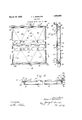
Iii the drawings forming a part of this specification, Fig. 1 is an elevational view of a car side door embodying my improvements, portions being broken away inorder to beth ter accommodate the view on the sheet. Fig.
2 a vertical sectional view corresponding approximately to the line 2 2 of Fig. 1; parts being broken away in this view also.
And Fig. 3 is a horizontal sectional view corresponding to the line 3-3 of Fig. 1, parts being broken away.
In carrying out my invention, I provide a suitable frame of rectangular outline, the same being shown as comprised of two vertical T-bars 10-10, an upper horizontal T-bar 11` and a lower horizontal T-bar 12. The T-bars are so arranged as to have their medial flanges 13-13 extending outwardly, that is, away from the inner plane of the door, and with their base flanges 14 and 15 extending routwardly and inwardly, respectively, with reference to the center of the door.r
Vith this construction, it is apparent that the inwardly extending flanges 15 are around all sides of the door and provide efficient means for the attachment of the braces, hereinafter described. Also, the outwardly extended base flange 14 of the front vertical T- bar 10 is adaptedto enter beneath the iiange 16 of a Weatheisealing member 17, such as transversely extending brace 22; secured. at', its ends as indicated at 23-23fto `the inward-r 'ly` extending base flanges 15 of tlieside T- n bars, said` brace 22 preferably beingv of lat plate-like form,.as best indicated in Fig.
To further brace and rioidify the `frame of the door-,I provide four diagonally.v eX-.
tending, braces 27-27. Each brace 27 has one endy thereof secured to the inwardly. ex
tending base flange 150i a side T-bar at aA point closely. adjacent: the crossbrace 22, asindicated at 23'23. From this point of. attachment, the brace 27 extends diagonally toward thecenter pointV of the corresponding top or bottom edge of the door and is there secured to the correspondingly inwardly eX- tendingbase Haiige 15 of the upper or lowerg T-bar, 11 or 12,` asindicated at 25-2'5. Thebraces 27'are preferably of tubular forma.- tion',.flattenedat` their ends, as best` indicated in Figs..2 and 3, where the same` areattached to the corresponding T-bars. As further means ofA bracingthe doorl frame `.and parl ticularly to prevent skewing thereoil provide. secondary. braces 26V of similar construcA tionto the braces 27, each of said secondary braces 26being secured by its iiattenedend Vin a corner of the frame, as indicated at ,2S-and having its other iattened end secured -to anintermediate flattened portion. of the corresponding adjacent brace 27, as indicated at 29-*29 With this construction, it is evident'. that the frame and. bracing therefor rmay be fabricated Vat comparativelysmall i expense; the same isrelatively light; andV isv well adapted to resist. distortion in` any direction..
The. frame and. braces` are shown as cov ered or sheathed kby upper and lower sheet,
My improved door may be used with either top hung or bottom hung fixtures, a bottom hung arrangement being shown for purposes of illustration and comprising rollers E, rotatably journaled, within the door and having portions thereof projecting through suit-- able slots in the bottom of the door and riding upon a horizontal track D, it being noted that the depending or outer base liange 14 of the bottom T-bar is positioned behind the track D and serv-es to prevent the door from coming off the track. The upper edge of the door may be held in place by any suitable means, such as the guard rail C having a depending flange 38 overlying the adjacent base flange 14 of the upper T-bar 11.
Although I have herein shown and described what I now consider' the preferred manner of carrying out my invention, the same is merely illustrative and I contemplate all changes and modifications that come within the scope of the claims appended hereto.
I claim:
1. In a car door, the combination with a frame comprised of upper, lower and side T-bars having the medial flanges thereof extending outwardly; and sheet metal panels having their marginal portions flanged and overlying said medial flanges and secured thereto.
2. In a car door, the combination with a frame comprised of upper, lower and side T-bars having the medial flanges thereof eX- tending outwardly; sheet metal panels havingvtheir marginal portions flanged and overlying said medial flanges and secured thereto and diagonally disposed braces each` secured t its ends to intermediate points of two T- ars.
3. As an article of mannfacture,'a car side door comprising a frame having vertical front and rear and upper horizontal rolled meinbers, each of said members including a section extending perpendicularly to the main plane of the door; a weather sealing formation along the rear vertical edge of the door adapted to cooperate with a corresponding sealing arrangement carried by a Car side; metal braces for said frame, each of which is riveted to one of said vertical side memof May, 1928.
ALLAN S. BARROWS.
Priority Applications (1)
| Application Number | Priority Date | Filing Date | Title |
|---|---|---|---|
| US280426A US1851693A (en) | 1924-06-27 | 1928-05-25 | Car door |
Applications Claiming Priority (2)
| Application Number | Priority Date | Filing Date | Title |
|---|---|---|---|
| US722759A US1752286A (en) | 1924-06-27 | 1924-06-27 | Car door |
| US280426A US1851693A (en) | 1924-06-27 | 1928-05-25 | Car door |
Publications (1)
| Publication Number | Publication Date |
|---|---|
| US1851693A true US1851693A (en) | 1932-03-29 |
Family
ID=26960297
Family Applications (1)
| Application Number | Title | Priority Date | Filing Date |
|---|---|---|---|
| US280426A Expired - Lifetime US1851693A (en) | 1924-06-27 | 1928-05-25 | Car door |
Country Status (1)
| Country | Link |
|---|---|
| US (1) | US1851693A (en) |
Cited By (1)
| Publication number | Priority date | Publication date | Assignee | Title |
|---|---|---|---|---|
| US2698068A (en) * | 1950-11-10 | 1954-12-28 | Frank J Hein | Vehicle dive arrester |
-
1928
- 1928-05-25 US US280426A patent/US1851693A/en not_active Expired - Lifetime
Cited By (1)
| Publication number | Priority date | Publication date | Assignee | Title |
|---|---|---|---|---|
| US2698068A (en) * | 1950-11-10 | 1954-12-28 | Frank J Hein | Vehicle dive arrester |
Similar Documents
| Publication | Publication Date | Title |
|---|---|---|
| US1240634A (en) | Railway-car door. | |
| US1851693A (en) | Car door | |
| US1170691A (en) | Portable building construction. | |
| US1902546A (en) | Metal door construction | |
| US1689472A (en) | Metallic car door | |
| US2592545A (en) | Cover panels for vehicles, especially railway cars | |
| US1506026A (en) | Bottom-supported car door | |
| US1749191A (en) | Foldable curtain | |
| US1958775A (en) | Transportation container | |
| GB337525A (en) | Improvements in and relating to the construction of roofings, partitions and the like | |
| US1806173A (en) | Car | |
| US1168539A (en) | Car-door. | |
| US1788292A (en) | Welded railway car | |
| US1675074A (en) | Bus-body sill | |
| US1639264A (en) | Wall structure for railway cars | |
| US978300A (en) | Sheet-metal door and the like. | |
| US1882477A (en) | Car roof | |
| US1218624A (en) | Car-roof. | |
| GB197723A (en) | Improvements in or relating to railway and like vehicles | |
| US1114000A (en) | Car structure. | |
| US1863969A (en) | Door construction | |
| US1817346A (en) | Car door | |
| US1756455A (en) | Car door | |
| US2092959A (en) | Car side construction | |
| US1774115A (en) | Metal box car |