US1851675A - Make-up device for printing forms - Google Patents
Make-up device for printing forms Download PDFInfo
- Publication number
- US1851675A US1851675A US373121A US37312129A US1851675A US 1851675 A US1851675 A US 1851675A US 373121 A US373121 A US 373121A US 37312129 A US37312129 A US 37312129A US 1851675 A US1851675 A US 1851675A
- Authority
- US
- United States
- Prior art keywords
- bars
- elements
- slots
- make
- cut
- Prior art date
- Legal status (The legal status is an assumption and is not a legal conclusion. Google has not performed a legal analysis and makes no representation as to the accuracy of the status listed.)
- Expired - Lifetime
Links
- 238000007639 printing Methods 0.000 title description 11
- 230000002093 peripheral effect Effects 0.000 description 4
- LNEPOXFFQSENCJ-UHFFFAOYSA-N haloperidol Chemical compound C1CC(O)(C=2C=CC(Cl)=CC=2)CCN1CCCC(=O)C1=CC=C(F)C=C1 LNEPOXFFQSENCJ-UHFFFAOYSA-N 0.000 description 2
- 230000015572 biosynthetic process Effects 0.000 description 1
- 238000010276 construction Methods 0.000 description 1
Images
Classifications
-
- F—MECHANICAL ENGINEERING; LIGHTING; HEATING; WEAPONS; BLASTING
- F16—ENGINEERING ELEMENTS AND UNITS; GENERAL MEASURES FOR PRODUCING AND MAINTAINING EFFECTIVE FUNCTIONING OF MACHINES OR INSTALLATIONS; THERMAL INSULATION IN GENERAL
- F16F—SPRINGS; SHOCK-ABSORBERS; MEANS FOR DAMPING VIBRATION
- F16F9/00—Springs, vibration-dampers, shock-absorbers, or similarly-constructed movement-dampers using a fluid or the equivalent as damping medium
- F16F9/10—Springs, vibration-dampers, shock-absorbers, or similarly-constructed movement-dampers using a fluid or the equivalent as damping medium using liquid only; using a fluid of which the nature is immaterial
- F16F9/12—Devices with one or more rotary vanes turning in the fluid any throttling effect being immaterial, i.e. damping by viscous shear effect only
-
- B—PERFORMING OPERATIONS; TRANSPORTING
- B41—PRINTING; LINING MACHINES; TYPEWRITERS; STAMPS
- B41B—MACHINES OR ACCESSORIES FOR MAKING, SETTING, OR DISTRIBUTING TYPE; TYPE; PHOTOGRAPHIC OR PHOTOELECTRIC COMPOSING DEVICES
- B41B1/00—Elements or appliances for hand composition; Chases, quoins, or galleys
Definitions
- This invention relates generally tomakeup devices for printing forms, and more particularly to an improved device adapted to provide space in aprinting form for cuts, the
- the device disclosed herein which, briefly stated, comprises a plurality of elements provided with slots adapted to receive the end portions of bars.
- the slotted elements are so constructed that said elements andthe bars associatedtherewith may be assembled to provide structures of various shapes and dimensions, hence structures provided by assembling said parts may be employed to provide spaces in print ing forms for cuts of a great variety of shapes 7 and sizes.
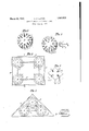
- Fig. '1 is a perspective of one of the slotted Fig. 3 is aview similar to Fig. 2, but show 1929.
- Fig. 4.- illustrates a modified form of the invention. 7
- Fig. 5 is a perspective showing a quad provided With slots so that same may be used as a part of the invention.
- a plurality of the elements B is arranged in the relative positions necessary to provide 7 a make-up device of the. desired configuration, and said elements are joined together. by bars C, the opposite end portions of Which are in troduced into certain of the radialwslots of said elements. Due tothe fact that the ra., dial slotsare quite numerous, and because I the slots 1-,
- the bars C may be extended in a great variety of angles, hence the make-up device may be caused to assume a very great number of shapes. Also, inasmuch as the bars C may be of various lengths, the dimensions of the make-up device may vary as desired.
- the make-up device has been assent bled and is in place in the form, said form is completed by arranging the type of the form in place about the make-up device.
- the form having been completed except for the presence of the .cut therein, and the cut now being available, the make-up device A is removed from the form either by lifting the same out as a unit, or by dissembling the various parts of which said make-up device is comprised and removing said device piece b piece after which the cut is arran ed in A 7 I b the space in the form provided therefor by the make-up device A and the form is locked up and is ready for use.
- Fig. 4 I illustrate a form of the invention in accordance with which the inner ends ofihe slots 1 of'the elements B are provided with slightly enlarged circular portions 2. Also in this form of the invention the bars C are provided at the ends thereof with enlarged circular portions 3 which enter the circular portions of the slots 1 when the end portions of the bars C are introduced into The bars C are also provided with shoulders at, which contact with the peripheral faces :of the elements B when the end portions ofthe bars 1C are extended into the slots 1, The circular port-ions of the slots 1 and the bars C and the shoulders 4 contacting with the peripheral faces of the elements l serrve to securely lock the elements 13 and barszC' together, which condition is highly desirable in some typesofprinting form building.
- Fig. 5 I illustrate the manner of preparing a quad for use as a part of my device, said quad 5 being provided with slots 6, which are adapted to receive the end portions of the bars C (not shown in Fig. 5) in the same manner that the slots 1 of the elements B of the preferred construction of the invention receive said bars.
- the quads may, in certain types of work, be used in place of the elements B and B.
- a make-up device for printing forms comprising a plurality of elements having a plurality of radially formed slots formed in each thereof, and bars for joining said elements together, theend portions of said bars being extended into certain of the slots formed in said elements and said bars being separable from said elements.
- a makeup device for printing forms comprising a. plurality of elements having a plurality of radially formed slots of varying lengths formed in each thereof, andbars for joining said elements together, the .end portions of said bars being extended into certain of the slots formed in said elements and said bars being separable from said elements.
- 31A makerup device for printing forms comprising a plurality'of elements having a plurality of slots formed in each thereof, bars for joining said elements together, the end portions of said bars being extended into Certain of the slots formed in'said elements, and marginal bars surrounding the assem bled elements and bars for providing, the device with fiat marginal walls.
- a malzeaipdevice for p 'inting forms comprising a pluralityof elements having a plurality of slots formed in each thereof, bars. for joining said elements together, the end portions of said bars being extended into certain of the slots formed in said elements, and marginal bars surrounding the assemb d elements and bars for providing the deice with flat marginal walls, said marginal bars being arranged in contact with faces of said elements.
Landscapes
- Engineering & Computer Science (AREA)
- General Engineering & Computer Science (AREA)
- Mechanical Engineering (AREA)
- Joining Of Building Structures In Genera (AREA)
Description
March 29, 1932. R. c. LINTON 1,851,675
MAKE-UP DEVICE FOR PRINTING FORMS Filed June 24, 1929 Anew/var Patented Mar. .29, 1932 PA'TENT'OFFICE ROBERT C. LINTON, F MAPLEWOOD, MISSOURI MAKE-UP .DEViCE FOR PRINTING Forms Application filed June 24,
This invention relates generally tomakeup devices for printing forms, and more particularly to an improved device adapted to provide space in aprinting form for cuts, the
a predominant object of the invention beingto provide improved means of this type com prised of separable parts which may be quickly and easily assembled and dissembled in use. 7
H In making up' printing forms intended for use particularly in printing newspapers it frequently happens that a out, Which is to form part of a printing form, is not available at the time the form is being made up, and when this situation arose prior to this invention it was necessary that a piece of material .be cut to. the size of the unavailable cut, and this piece of material was arranged in the form in the position of the cut so as to 29 maintain a space in the cut of the size and shape of the cut. With the piece of material referred to arranged in-the' form inthe position of the cut, the type ofthe form was arranged about the position of the cut, and
when the cut was received the piece of material was removed from the formand the cut substituted therefor.
Due to the fact that much time was con- 7 sumed in cutting and preparing the piece of material which heretofore provided the space for the cut, I have provided the device disclosed herein, which, briefly stated, comprises a plurality of elements provided with slots adapted to receive the end portions of bars.
"" The slotted elements are so constructed that said elements andthe bars associatedtherewith may be assembled to provide structures of various shapes and dimensions, hence structures provided by assembling said parts may be employed to provide spaces in print ing forms for cuts of a great variety of shapes 7 and sizes.
Fig. '1 is a perspective of one of the slotted Fig. 3 is aview similar to Fig. 2, but show 1929. Serial N0. 373,121.
ing the device as same, will appear when arranged in triangular formation.
Fig. 4.- illustrates a modified form of the invention. 7
Fig. 5 is a perspective showing a quad provided With slots so that same may be used as a part of the invention.
, than others thereof. I p v The opposite end portions of the bars C are 7( extended into certain of the radial slots 1 of the elements B. in a manner to join said. elements together, and said bars C extend between said elements in the manner indicated in'Figs. 2 and 3. If desired, I may taper the slots 1 very slightly from top to bottom with the wider portion ofthe slots located at the top of the elements B, and inthis event I the bars G, or at least the opposite end portions thereof, will be correspondingly ta-' 30 pered. This arrangement will assurefree passage of the end portions of the bars into the slots and close contact between the side facesof the bars and thewalls of the slots, whereby a very rigid structure will be provid- 8d ed. Arranged to surround the structure comprised of theelements Band bars C. are
-bars D, Which provide the built-up structure with fiatmarginal walls, said bars being arranged in contact with the peripheral faces 9? of, the elements B, as shown in Figs. 2 and 3.
Iii-the use of myimpro ed device, a plurality of the elements B is arranged in the relative positions necessary to provide 7 a make-up device of the. desired configuration, and said elements are joined together. by bars C, the opposite end portions of Which are in troduced into certain of the radialwslots of said elements. Due tothe fact that the ra., dial slotsare quite numerous, and because I the slots 1-,
said slots extend entirely around the elements B, the bars C may be extended in a great variety of angles, hence the make-up device may be caused to assume a very great number of shapes. Also, inasmuch as the bars C may be of various lengths, the dimensions of the make-up device may vary as desired. After the elements B and the bars C are assembled as described, the marginal bars D are arranged in contact with the peripheral faces of said elements to provide the make-up device with fiat marginal walls.
lVhen the make-up device has been assent bled and is in place in the form, said form is completed by arranging the type of the form in place about the make-up device. The form having been completed except for the presence of the .cut therein, and the cut now being available, the make-up device A is removed from the form either by lifting the same out as a unit, or by dissembling the various parts of which said make-up device is comprised and removing said device piece b piece after which the cut is arran ed in A 7 I b the space in the form provided therefor by the make-up device A and the form is locked up and is ready for use.
In Fig. 4 I illustrate a form of the invention in accordance with which the inner ends ofihe slots 1 of'the elements B are provided with slightly enlarged circular portions 2. Also in this form of the invention the bars C are provided at the ends thereof with enlarged circular portions 3 which enter the circular portions of the slots 1 when the end portions of the bars C are introduced into The bars C are also provided with shoulders at, which contact with the peripheral faces :of the elements B when the end portions ofthe bars 1C are extended into the slots 1, The circular port-ions of the slots 1 and the bars C and the shoulders 4 contacting with the peripheral faces of the elements l serrve to securely lock the elements 13 and barszC' together, which condition is highly desirable in some typesofprinting form building.
In Fig. 5 I illustrate the manner of preparing a quad for use as a part of my device, said quad 5 being provided with slots 6, which are adapted to receive the end portions of the bars C (not shown in Fig. 5) in the same manner that the slots 1 of the elements B of the preferred construction of the invention receive said bars. When constructed as shown in Fig. 5, the quads may, in certain types of work, be used in place of the elements B and B.
1. A make-up device for printing forms comprising a plurality of elements having a plurality of radially formed slots formed in each thereof, and bars for joining said elements together, theend portions of said bars being extended into certain of the slots formed in said elements and said bars being separable from said elements.
2. A makeup device for printing forms comprising a. plurality of elements having a plurality of radially formed slots of varying lengths formed in each thereof, andbars for joining said elements together, the .end portions of said bars being extended into certain of the slots formed in said elements and said bars being separable from said elements.
31A makerup device for printing forms comprising a plurality'of elements having a plurality of slots formed in each thereof, bars for joining said elements together, the end portions of said bars being extended into Certain of the slots formed in'said elements, and marginal bars surrounding the assem bled elements and bars for providing, the device with fiat marginal walls.
4. A malzeaipdevice for p 'inting forms comprisinga pluralityof elements having a plurality of slots formed in each thereof, bars. for joining said elements together, the end portions of said bars being extended into certain of the slots formed in said elements, and marginal bars surrounding the assemb d elements and bars for providing the deice with flat marginal walls, said marginal bars being arranged in contact with faces of said elements.
In testimony that I claim the foregoing I hereuntonfiix my signature.
ROBERT C. LINTON.
Priority Applications (1)
| Application Number | Priority Date | Filing Date | Title |
|---|---|---|---|
| US373121A US1851675A (en) | 1929-06-24 | 1929-06-24 | Make-up device for printing forms |
Applications Claiming Priority (1)
| Application Number | Priority Date | Filing Date | Title |
|---|---|---|---|
| US373121A US1851675A (en) | 1929-06-24 | 1929-06-24 | Make-up device for printing forms |
Publications (1)
| Publication Number | Publication Date |
|---|---|
| US1851675A true US1851675A (en) | 1932-03-29 |
Family
ID=23471055
Family Applications (1)
| Application Number | Title | Priority Date | Filing Date |
|---|---|---|---|
| US373121A Expired - Lifetime US1851675A (en) | 1929-06-24 | 1929-06-24 | Make-up device for printing forms |
Country Status (1)
| Country | Link |
|---|---|
| US (1) | US1851675A (en) |
-
1929
- 1929-06-24 US US373121A patent/US1851675A/en not_active Expired - Lifetime
Similar Documents
| Publication | Publication Date | Title |
|---|---|---|
| US1851675A (en) | Make-up device for printing forms | |
| DE447684C (en) | Umbrella with an oval roof | |
| SU26038A1 (en) | Ring key for connecting parts of wooden structures | |
| US1585136A (en) | Chaplet for molding | |
| US964949A (en) | Support for the internal molds of hollow castings. | |
| FR600366A (en) | Fan-compressor with so-called helicoid-centripetal vane propeller | |
| SU11930A1 (en) | A method of manufacturing reinforced concrete window covers | |
| US1535432A (en) | milbradt | |
| SU15285A1 (en) | The method of obtaining terpingidrata | |
| USD70905S (en) | Design for a combination desk set | |
| GB232203A (en) | Improvements in sieves | |
| ES111551A3 (en) | A procedure for the manufacture of chocolate bars. | |
| FR644421A (en) | Stuff box with adjustable ring body | |
| GB249980A (en) | Improvements in or relating to sectional buildings and slabs for constructing the same | |
| FR603167A (en) | Eccentric vane propellants | |
| FR623476A (en) | Advanced freewheel locking | |
| ES94755A3 (en) | A procedure for the manufacture of galalith plates and bars. | |
| FR649653A (en) | Wax knife | |
| ES99139A1 (en) | A locking wedge for the grooves of electrical machines. | |
| ES96402A1 (en) | A procedure for the manufacture of permanent solid colors. | |
| GB251668A (en) | Improvements relating to type setting and casting machines | |
| FR636883A (en) | Rotary vane compressor | |
| ES102300A1 (en) | A procedure to obtain drawings cut and cut on paper. | |
| ES101995A1 (en) | A machine for making holes for rivets. | |
| ES94591A1 (en) | Special types and keyboard for stenographic machine. |