US1851646A - Locomotive stoker - Google Patents
Locomotive stoker Download PDFInfo
- Publication number
- US1851646A US1851646A US313233A US31323328A US1851646A US 1851646 A US1851646 A US 1851646A US 313233 A US313233 A US 313233A US 31323328 A US31323328 A US 31323328A US 1851646 A US1851646 A US 1851646A
- Authority
- US
- United States
- Prior art keywords
- grate
- protecting
- conduit
- backhead
- stoker
- Prior art date
- Legal status (The legal status is an assumption and is not a legal conclusion. Google has not performed a legal analysis and makes no representation as to the accuracy of the status listed.)
- Expired - Lifetime
Links
- 230000003137 locomotive effect Effects 0.000 title description 12
- 239000000446 fuel Substances 0.000 description 8
- 210000002445 nipple Anatomy 0.000 description 4
- 238000002485 combustion reaction Methods 0.000 description 3
- 238000010276 construction Methods 0.000 description 3
- 230000008602 contraction Effects 0.000 description 2
- 230000015572 biosynthetic process Effects 0.000 description 1
- 238000001816 cooling Methods 0.000 description 1
- 238000009434 installation Methods 0.000 description 1
- 238000013021 overheating Methods 0.000 description 1
Images
Classifications
-
- F—MECHANICAL ENGINEERING; LIGHTING; HEATING; WEAPONS; BLASTING
- F23—COMBUSTION APPARATUS; COMBUSTION PROCESSES
- F23K—FEEDING FUEL TO COMBUSTION APPARATUS
- F23K3/00—Feeding or distributing of lump or pulverulent fuel to combustion apparatus
- F23K3/04—Feeding or distributing of lump or pulverulent fuel to combustion apparatus for locomotive boiler furnaces
Definitions
- This invention relates to that type of stoker which conveys thefuel from the source of supply by a conveyor tube or conduit, the forward or delivery end of which extends into, the boiler firebox or furnace and which isV protected from the intense heat generated inthe iirebox by an auxiliary or protecting grate. More specifically, the invention particularly relates to improved means for securing the auxiliary or protecting grate in its proper position.
- stokers of this type the fuel is delivered to the rebox through a conduit, the forward end of which extends above the flrebox grates and terminates in a discharge opening at a height above the grate from which the fuel emerging from the discharge opening can be scattered over the re by' suitable spreading means, such as steamjets.
- suitable spreading means such as steamjets.
- the discharge end no of the conduit being thus exposed to the intense heat of the firebox, it is necessary to use somey means for protecting it from the re and-for this purpose there is usually provided an .auxiliary or protecting grate which is in the form of an upstanding perforated wall or skirt extending about the exposed end of the stoker conduit as is generally exempliiied in the United States Letters Patent 1,606,182, granted to Frank P. Roesch, ondate of November V19, 1926.
- steam'locomotives to which this invention is especiallyl applicable are constructed to permit the rear 'end ⁇ of the boiler to move on the locomotive frame so as'to provide for expansion and contraction of the boiler.
- stokers of the character shown, to locomotive boilers it is cus ⁇ tomary to secure the delivery or discharge 40 conduit to the locomotive frame and apply the protecting grate about the upper ⁇ end of the conduit in a manner adapted for it to move with the boiler without striking or dis-V placing the stoker conduit.
- the space between the stoker conduit and the protecting grate is covered at the top and opens downwardly into the ash pan or to the atmosphere which space provides for the passage of air around the stoker conduit and into the 450 combustion' chamber through the perfora ⁇ conduit.
- the protecting grate prevents the flame from coming into contact with the Stoker conduit and the vpassage of air throughthe perfoi rated wall prevents overheating of the con'- duit and also of the protecting grate.
- the present invention has for its object to overcomethe yobjectionable features of prior', construction by providing improved detachable and securermeans for maintaining the protecting'grate in proper'posit'i'onv to vprovide for the positive circulation of air therethrough.
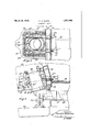
- Fig. 1 is a fragmentary central longitudinalk 9G vertical section through? the rear portion of a boiler firebox with ay stokerappliedthereto;
- Y Fig. 2 is a detail plan section on theline. 2 2 of Figure 1 looking inthe direction ofV the arrows. l y,
- l y For the purpose of best illustratingv the ⁇ invention, it is shown'on the drawings and will@ be described as used with a locomotive but it will berecognizedthat it can be used to 1G v good advantage with other types of boiler stoker installations.
- the rear portion of a locomotive fireboX lO' has a hollow backwall or backhead 11 comprising inner and outer sheets 12 and 13, respectively,
- the stoker conveyor conduitv 17 is iixedly wardly tothe inside sheet 12 ofthebackhead'V vmounted to the .locomotiveframe 23 by the bracket 24.
- auxiliary Y or protecting grateindicated as a whole at 25 which inthe-preferred -form of construction comprises four castmetal sections 26, 27, 28 and 29, all of which arespaced from the conduit 19 andform acorresponding chamberor opening 30 with the opening 16 of theY center bar 15.
- Sections 26 and28 of theiprotecting grate forming right and left hand .sections respectively, aresupported on the forked portion of the bar 15, each Vsection being provided at the lower edgeY withfy depending lugs as at 31 Vwhich'lugs are intended-to assist in maintainingeachlsectio'n in* position'. on the Vbar 15.V
- the upper sections 27 and 29 rest'on theY top of sections 26 ,and-,28 and each section is formed with lugs.'
- each of the forward transverse .walls ofthe lower gratesections 26 and j '28* is i y'ftted and held thereto by aV Y 76 ⁇ vnovel securingA means in'which this invenv provided rearwardly extending lugs 33, 33a, each of said lugs having. an opening therethroughasat 341, 34a, vwhich openings are adapted to receive the hook portion 35 of a securing bolt 36, as shown there are two such bolts provided, one on either side of the stoker conduit portion 19.
- the main body of the bolt 36 extends rearwardly and projects through a nipple 37 or' 37a of the backhead 11.
- the nipple or sleeve v37, 37a has its ends ⁇ rolled or beadedoverqfor Vsealed engagement ⁇ withk the inner and ,outersheets of the backhead to form a passage through the backhead for the securing bolt 36, one nipple or e sleeve being employed with each bolt.
- YMounted overV lthe threaded end of each of the bolts 36 is a washer or bearing Aplate V38 lof such diameter" that a portion of'it bears onthe beaded portion of the nipple against.
- Locking nuts as at 39 are in threaded en
- gagement with the threaded end of thebolt 36 may be adjusted to bear againstthe bearing plate to cause the bolt 36 to tightly hold the protecting grate sections against.
- openings 40 which serverto Vpermit'the air: from the chamber 30 and' opening 16 to flow into the combustion chamber, thus assist-ing in the complete combustion of the fuel and servingto cool the conduit 19and the pro-4 Y tecting grate sections.
- the protecting'grate may be made of one part or as many sections as desirable or any form ofcooling.
- wall may be Vvused for the purpose described, and held in'proper Yposition ing means of this invention.
- the combinationv comprising .a fireboxrbackhead, a Yfurnace grateextending forwardly from theback head, a conduit extending upward 'into thej iireboX and having itsV delivery end yat a partially surrounding the delivery*vend of Vpoint above saidgrate, a protecting grate ina said conduit in spaced relation therewith, and adjustable attachment means extending through the firebox backhead for detachably securing said protecting grate thereto.
- the combination comprising a irebox backhead, a furnace grate extending forwardly from the backhead, a conduit extending upward into the iirebox and having its delivery end at a point above said grate, a protecting grate having an open end, said protecting grate partially surrounding the delivery end of said conduit in spaced relation therewith and having its open end in contact with the backhead, and bolts engaging said protecting grate and extending through the backhead for securing the protecting grate thereto.
- the combination comprising a iirebox backhead, a furnace grate extending forwardly from the backhead, a fuel conduit extending upward into the irebox and having its delivery end at a point above said grate, an upstanding substantially U-shaped protecting wall within the firebox partially surrounding the delivery end of the conduit and in spaced relation therewith and having its open end in contact with the backhead, said protecting wall comprising sections separable on a vertical plane and bolts engaging each of said sections and extending through the backhead for securing said sections thereto.
- a locomotive Stoker' comprising a hollow iirebox backhead formed by inner and outerl sheets, a furnace grate extending forwardly from the backhead, a fuel conduit extending upward into the firebox and having its delivery endV at a point above said grate thereof, an upstanding substantially U-shaped protecting grate partially surrounding the delivery end of the conduit and in spaced relation therewith and having its open end in contact with the inner sheet of said hollow backhead, means for securing the open end of said protecting grate in Contact with said inner sheet, said securing means comprising a plurality of lugs extending from the inner face'of said protecting grate, each being adapted to receive one end of a respective securing bolt, a plurality of bolts each having a hook portion engaging one of said lugs, the body portion of each bolt extending rearwardly through a respective sleeve in said hollow backhead and means cooperating with the body por# tion for securing said bolt in adjustable locking engagement with the outer sheet of
- a locomotive stoker comprising a hollow frebox backhead formed by inner and outer sheets, a furnace grate extending forwardly from the backhead, a fuel conduit extending upward into the firebox and having its delivery end at a point above the grate thereof, a perforatedl upstanding substantially U-shaped protecting grate partially surrounding the delivery end of the conduit and in spaced relation therewith, said protecting grate comprising sections separable on a vertical plane and attachment means extending through the fire box backhead detachably securing each of said sections thereto.
Landscapes
- Engineering & Computer Science (AREA)
- Chemical & Material Sciences (AREA)
- Combustion & Propulsion (AREA)
- Mechanical Engineering (AREA)
- General Engineering & Computer Science (AREA)
- Incineration Of Waste (AREA)
Description
March 29,1932. '.c.. H. QUINN LOCQMOTIVE STOKER Filed Oct.
Patented Mar. 29, 1932 UNITED STATES PATENT oFFIcES CHARLES H. QUINN, OF SAN FRANCISCO,l CALIFORNIA, ASSIGNOR TO THE STANDARD- STOKER COMPANY, INCORPORATED, vA CORPORATION OF DELAWARE LOCOMQTIVE STOKER Application led October 18, `192.8. Serial No. 313,233.V
This invention relates to that type of stoker which conveys thefuel from the source of supply by a conveyor tube or conduit, the forward or delivery end of which extends into, the boiler firebox or furnace and which isV protected from the intense heat generated inthe iirebox by an auxiliary or protecting grate. More specifically, the invention particularly relates to improved means for securing the auxiliary or protecting grate in its proper position.
In stokers of this type the fuel is delivered to the rebox through a conduit, the forward end of which extends above the flrebox grates and terminates in a discharge opening at a height above the grate from which the fuel emerging from the discharge opening can be scattered over the re by' suitable spreading means, such as steamjets. The discharge end no of the conduit being thus exposed to the intense heat of the firebox, it is necessary to use somey means for protecting it from the re and-for this purpose there is usually provided an .auxiliary or protecting grate which is in the form of an upstanding perforated wall or skirt extending about the exposed end of the stoker conduit as is generally exempliiied in the United States Letters Patent 1,606,182, granted to Frank P. Roesch, ondate of November V19, 1926.
As clearly brought out in the aforesaid patent,= steam'locomotives to which this invention is especiallyl applicable are constructed to permit the rear 'end `of the boiler to move on the locomotive frame so as'to provide for expansion and contraction of the boiler. When installing stokers of the character shown, to locomotive boilers, it is cus` tomary to secure the delivery or discharge 40 conduit to the locomotive frame and apply the protecting grate about the upper` end of the conduit in a manner adapted for it to move with the boiler without striking or dis-V placing the stoker conduit. The space between the stoker conduit and the protecting grate is covered at the top and opens downwardly into the ash pan or to the atmosphere which space provides for the passage of air around the stoker conduit and into the 450 combustion' chamber through the perfora` conduit.
tions in the protecting grate, and thus the protecting grate prevents the flame from coming into contact with the Stoker conduit and the vpassage of air throughthe perfoi rated wall prevents overheating of the con'- duit and also of the protecting grate.
' It is ordinary practice to mountthe protecting grate in positionl within the irebox on the grate center bearer or bar and providing Y depending lugs from the protecting grate which are intended to prevent slippage of i. the protecting grate and hold it closely to the backwall of the iirebox. y While the manufacturer of the' stoker constructs vthe stoking device andthe protecting grate in accord?- ance with the locomotivespeciiications it is.
- common practice to find that the protecting grate does not t .closely -to'the'backwall of the firebox or that the depending'lugs are not in proper position to prevent-forward orsidewise slipping .motion of the protecting grate which results in the formation of large gaps 'or spaces, *whichv offering the pathof ver' least resistance tothe inlowing airwill per- .y
mit the air to enter the iirebox throughE the large gaps or spaces instead of through the,l perforated openings in the protecting grate which has theefect of permittingtheheat of the fireto burn away the same destroying its value and in time damaging the stoker The present invention has for its object to overcomethe yobjectionable features of prior', construction by providing improved detachable and securermeans for maintaining the protecting'grate in proper'posit'i'onv to vprovide for the positive circulation of air therethrough. y j A v On the drawings,
` Fig. 1 is a fragmentary central longitudinalk 9G vertical section through? the rear portion of a boiler firebox with ay stokerappliedthereto;
and Y Fig. 2 is a detail plan section on theline. 2 2 ofFigure 1 looking inthe direction ofV the arrows. l y, For the purpose of best illustratingv the `invention, it is shown'on the drawings and will@ be described as used with a locomotive but it will berecognizedthat it can be used to 1G v good advantage with other types of boiler stoker installations.
Referring descriptively to the drawings,the rear portion of a locomotive fireboX lO'has a hollow backwall or backhead 11 comprising inner and outer sheets 12 and 13, respectively,
. the hollow portion being closed at its bottom end by a mud ring 14 to which the sheets 12 and 13 are secured. Within the fireboX 10 y, upper extendingportion 19 at its forward end which extendsinto lthe firebox through the opening 16 to alpoint above the level ofthe fire -to be maintained, and terminates in a discharge or delivery opening 20.V Fuel is conveyed through the conduit 17 V'and forced upwardly through the yportion 19 by a screw conveyor 21.-,v As the fuel emerges from the discharge opening 20 itis projected and scat-A- tered over the lirebed by a suitable steam blast discharged from the distributorfhead 22.`
.. The stoker conveyor conduitv 17 is iixedly wardly tothe inside sheet 12 ofthebackhead'V vmounted to the .locomotiveframe 23 by the bracket 24.
lPartially surrounding `the upper end portion 19 of thestoker conduit is an auxiliary Y or protecting grateindicated as a whole at 25 which inthe-preferred -form of construction comprises four castmetal sections 26, 27, 28 and 29, all of which arespaced from the conduit 19 andform acorresponding chamberor opening 30 with the opening 16 of theY center bar 15. Sections 26 and28 of theiprotecting grate forming right and left hand .sections respectively, aresupported on the forked portion of the bar 15, each Vsection being provided at the lower edgeY withfy depending lugs as at 31 Vwhich'lugs are intended-to assist in maintainingeachlsectio'n in* position'. on the Vbar 15.V The upper sections 27 and 29 rest'on theY top of sections 26 ,and-,28 and each section is formed with lugs.'
32 similar to lugs 31 'for the purposeof preventingmovement of the top sections on the lower sectionsr26 and 28. The sidewalls of the protecting grate sections extend rearand are closel tion resides as vhereinafter described. f
, On the inner face'of each of the forward transverse .walls ofthe lower gratesections 26 and j '28* is i y'ftted and held thereto by aV Y 76` vnovel securingA means in'which this invenv provided rearwardly extending lugs 33, 33a, each of said lugs having. an opening therethroughasat 341, 34a, vwhich openings are adapted to receive the hook portion 35 of a securing bolt 36, as shown there are two such bolts provided, one on either side of the stoker conduit portion 19.
- The main body of the bolt 36, the opposite end of which from the hook portion is threaded, extends rearwardly and projects through a nipple 37 or' 37a of the backhead 11. The nipple or sleeve v37, 37a has its ends `rolled or beadedoverqfor Vsealed engagement` withk the inner and ,outersheets of the backhead to form a passage through the backhead for the securing bolt 36, one nipple or e sleeve being employed with each bolt.
YMounted overV lthe threaded end of each of the bolts 36 is a washer or bearing Aplate V38 lof such diameter" that a portion of'it bears onthe beaded portion of the nipple against.
the outside sheet 13 of the backwall 1,1.
Locking nuts as at 39 are in threaded en;
gagement with the threaded end of thebolt 36, and may be adjusted to bear againstthe bearing plate to cause the bolt 36 to tightly hold the protecting grate sections against.
the inner sheet 12 of the backhead.
Vco
All of the grate sections are formed with: "5
wallmay be Vvused for the purpose described, and held in'proper Yposition ing means of this invention.
bythe secur- From the above construction it'will v bek seen that the securing hook bolts,'while being detachable, serve to hold the protecting grate in proper relation withY the firebox backwall t;
at all times regardless of the'eXpansion or contraction of the boiler or its parts, and therefore insures the positive circulationV of the cooling air, thus increases thelife ofthe parts. Y
I claim:
1. In a locomotive stoker,thecombination comprising ,a reboxbackhead,-l a :furnace grate extending forwardly lfrom vthe backs.
head,.a conduit extending upward into V.the
firebox and havingits deliveryv end at a pointy above said grate, a' protecting grate i Y partially surrounding the deliveryk end of said conduit in spaced relation therewith,
and attachment means extending through the Y rebox backhead for securing saidl protect-I ing n grate thereto.
2. In alocomotive Stoker, the combinationv comprising .a lireboxrbackhead, a Yfurnace grateextending forwardly from theback head, a conduit extending upward 'into thej iireboX and having itsV delivery end yat a partially surrounding the delivery*vend of Vpoint above saidgrate, a protecting grate ina said conduit in spaced relation therewith, and adjustable attachment means extending through the firebox backhead for detachably securing said protecting grate thereto. 3. In a locomotive Stoker, the combination comprising a irebox backhead, a furnace grate extending forwardly from the backhead, a conduit extending upward into the iirebox and having its delivery end at a point above said grate, a protecting grate having an open end, said protecting grate partially surrounding the delivery end of said conduit in spaced relation therewith and having its open end in contact with the backhead, and bolts engaging said protecting grate and extending through the backhead for securing the protecting grate thereto.
4. In a locomotive Stoker, the combination comprising a iirebox backhead, a furnace grate extending forwardly from the backhead, a fuel conduit extending upward into the irebox and having its delivery end at a point above said grate, an upstanding substantially U-shaped protecting wall within the firebox partially surrounding the delivery end of the conduit and in spaced relation therewith and having its open end in contact with the backhead, said protecting wall comprising sections separable on a vertical plane and bolts engaging each of said sections and extending through the backhead for securing said sections thereto.
5. In a locomotive Stoker', the combination comprising a hollow iirebox backhead formed by inner and outerl sheets, a furnace grate extending forwardly from the backhead, a fuel conduit extending upward into the firebox and having its delivery endV at a point above said grate thereof, an upstanding substantially U-shaped protecting grate partially surrounding the delivery end of the conduit and in spaced relation therewith and having its open end in contact with the inner sheet of said hollow backhead, means for securing the open end of said protecting grate in Contact with said inner sheet, said securing means comprising a plurality of lugs extending from the inner face'of said protecting grate, each being adapted to receive one end of a respective securing bolt, a plurality of bolts each having a hook portion engaging one of said lugs, the body portion of each bolt extending rearwardly through a respective sleeve in said hollow backhead and means cooperating with the body por# tion for securing said bolt in adjustable locking engagement with the outer sheet of said backhead.
6. In a locomotive stoker, the combination comprising a hollow frebox backhead formed by inner and outer sheets, a furnace grate extending forwardly from the backhead, a fuel conduit extending upward into the firebox and having its delivery end at a point above the grate thereof, a perforatedl upstanding substantially U-shaped protecting grate partially surrounding the delivery end of the conduit and in spaced relation therewith, said protecting grate comprising sections separable on a vertical plane and attachment means extending through the fire box backhead detachably securing each of said sections thereto.
Y In testimony whereof I aix my signature.
CHARLES I-I. QUINN.
Priority Applications (1)
| Application Number | Priority Date | Filing Date | Title |
|---|---|---|---|
| US313233A US1851646A (en) | 1928-10-18 | 1928-10-18 | Locomotive stoker |
Applications Claiming Priority (1)
| Application Number | Priority Date | Filing Date | Title |
|---|---|---|---|
| US313233A US1851646A (en) | 1928-10-18 | 1928-10-18 | Locomotive stoker |
Publications (1)
| Publication Number | Publication Date |
|---|---|
| US1851646A true US1851646A (en) | 1932-03-29 |
Family
ID=23214897
Family Applications (1)
| Application Number | Title | Priority Date | Filing Date |
|---|---|---|---|
| US313233A Expired - Lifetime US1851646A (en) | 1928-10-18 | 1928-10-18 | Locomotive stoker |
Country Status (1)
| Country | Link |
|---|---|
| US (1) | US1851646A (en) |
-
1928
- 1928-10-18 US US313233A patent/US1851646A/en not_active Expired - Lifetime
Similar Documents
| Publication | Publication Date | Title |
|---|---|---|
| US1851646A (en) | Locomotive stoker | |
| US438872A (en) | And allan mason | |
| US744042A (en) | Locomotive steam-boiler. | |
| US1554636A (en) | Distributor for stokers | |
| US234972A (en) | William ennis | |
| US1688203A (en) | Fire-box foundation ring | |
| US1092852A (en) | Furnace and air-injecting nozzle therefor. | |
| US743825A (en) | Fire-tube boiler. | |
| US1154877A (en) | Smoke-consuming furnace. | |
| US1410687A (en) | Locomotive stoker | |
| US882634A (en) | Oil-grate. | |
| US711044A (en) | Locomotive-boiler. | |
| US1190952A (en) | Fire-box for locomotive or stationary boilers. | |
| US1585963A (en) | Smoke consumer | |
| US941547A (en) | Smoke-preventive apparatus. | |
| US540987A (en) | Furnace | |
| US525940A (en) | James a | |
| US1540042A (en) | Oil burner | |
| US1220394A (en) | Smokeless oven-furnace. | |
| US1606182A (en) | Stoker | |
| US235124A (en) | Peters | |
| US1508393A (en) | Method of and apparatus for firing the furnaces of steam generators and other furnaces | |
| US973110A (en) | Oil-burning steam-boiler. | |
| US841074A (en) | Smoke-consuming attachment for boiler-furnaces. | |
| US857170A (en) | Oil-burning steam-boiler. |