US1851640A - Resilient wheel - Google Patents
Resilient wheel Download PDFInfo
- Publication number
- US1851640A US1851640A US218740A US21874027A US1851640A US 1851640 A US1851640 A US 1851640A US 218740 A US218740 A US 218740A US 21874027 A US21874027 A US 21874027A US 1851640 A US1851640 A US 1851640A
- Authority
- US
- United States
- Prior art keywords
- disk
- wheel
- disks
- slot
- resilient
- Prior art date
- Legal status (The legal status is an assumption and is not a legal conclusion. Google has not performed a legal analysis and makes no representation as to the accuracy of the status listed.)
- Expired - Lifetime
Links
- 241000239290 Araneae Species 0.000 description 8
- 239000012858 resilient material Substances 0.000 description 6
- 239000007787 solid Substances 0.000 description 4
- 239000000463 material Substances 0.000 description 2
- 229910000639 Spring steel Inorganic materials 0.000 description 1
- 230000008602 contraction Effects 0.000 description 1
- 229910003460 diamond Inorganic materials 0.000 description 1
- 239000010432 diamond Substances 0.000 description 1
- 238000012986 modification Methods 0.000 description 1
- 230000004048 modification Effects 0.000 description 1
- 230000002093 peripheral effect Effects 0.000 description 1
Images

Classifications
-
- B—PERFORMING OPERATIONS; TRANSPORTING
- B60—VEHICLES IN GENERAL
- B60B—VEHICLE WHEELS; CASTORS; AXLES FOR WHEELS OR CASTORS; INCREASING WHEEL ADHESION
- B60B9/00—Wheels of high resiliency, e.g. with conical interacting pressure-surfaces
- B60B9/02—Wheels of high resiliency, e.g. with conical interacting pressure-surfaces using springs resiliently mounted bicycle rims
Definitions
- the present invention relates to wheels of the type provided with resilient webs, whereby movements ofthe wheel hub relative to the felly are permitted.
- the invention may take various forms, and several embodiments are shown in ⁇ the accompanying drawings,
- Figure 1 is a side plan view of a wheel embodying our invention.
- Figure 2 is a side plan view of a wheel provided with our novel structure in a second form.
- Figure 3 is a horizontal diametrical section ofFig. 1.
- Figure 4f is a diametrical section of Fig. 2.
- Figure 5 is a diametricalsection through a Wheel embodying our invention in still another form.
- Figure 6 is a diametrical section through a ⁇ .20 wheel embodying a further modified form.
- Figure 7 is a diametrical section through a wheel embodying our invention in substantially the form shown in Fig. 1, but with certain modications, and
- Figure 8 is a side plan view of a wheel ac*- cording to Fig. 7 with a part removed.
- our invention consists in the provision of a wheel web composed of one or more resilient disks suitably apertured so as to permit resilient movements of its center portion relative to its rim portion.
- the disk or disks, of which the web is composed may be composed of anysuitable material, preferably spring steel.
- a suitable perforation consists of a spiral slot generated about the rotational axis of the disk. In Figs. 1 and ⁇ 3, 10 indicates the disk and 11 the spiral slot therein.
- this means is shown to be a pair of spiders 12 and 13, one at each side of ldisk 10, the spiders and disk 10 being secured at their Acenters to hub flange 14 by means of bolts 15. 'Ihefends of the spider arms extend substantially beyond the outer peripheral limits of slot 11 so as to bear against the rigid rim portion of the disk ⁇ at all times. In this manner, all portions of 'disk 10 arealways kept in the same plane.
- Slot 11 is preferably in the form of an 75 Archimedean spiral, and it will be noted that the bounding Walls of the spiral converge at both ends of the latter.
- spiders 12 and 13 are replaced additional 'slotted disks ,19 and 20, one at eachside of a main slotted disk 10.
- the spirals of disks 19 4and 20 preferably run in .the opposite direction to the spiral of disk 10', that is, if the latter is right hand,the former areboth left hand.
- the pitch of the spiral slots yin the outer disks differs from that of the inner disk so that the. slots of the three disks will have the least possible coincidence.
- the web may comprise any desired number.
- the web consists of two spaced spirally slot-ted disks 21 and 22, and an intermediate solid disk 23 of suiiicient diameter to extend well within the solid rim portion of each. outer disk, and yet permit adequate radial movement of the hub toward the Jfelly.
- the center portions of the three disks are all rigidly secured to a hub element.
- the web may be composed j yot a sutliciently massive single disk, or an adequate number ot single disks.
- the single disk structure may be modified, as illustrated in Fig. 7, ⁇ Wherein it will be seen that spiral convolutions 24 of -disk 24 are considerably thickened, and asrhere shown, are substan- Vae vtially diamond shape in cross section.
- Fig. 8 illustrates the use of a central planefaced disk or plate 28 of the same design as disk 10 of Fig. 1, and two outer slotted disks 29 and 30 -whose convolutions are outwardly expanded to give them a substantially triangular cross section as at 31 and 32.
- Y slots ot discs 29 and 80 are of different pitch from that of disc 28, and run in the opposite direction thereto. As indicated in this figure, thel oppositely running slots all start at the left of ther hub.
- V33 and 34 are provided, the disks and plates being rigidly secured together at their center portions.
- the wheel may be made more etfective for traction purposes by providing the margins -ot plates' and 34 with apertures overlying the solid marginal portions yof discs 29 and 30, and pins, as at 29', may be secured to thelatter in position to project through the apertures, the result being the same as described in connection with F ig-f ure 1.
- width of the material between adjacent convolutions of the slot being materially greater than the normal width of the slot.
- a Wheel web comprising a plurality ot coaxially ydisposed resilient disks, each of said disks having a spiral slot generated about the common axis whereby radial movements ofthe center portions of the disks relative to their rim portions are permitted, the slots of adjacent disks being of diii'erent pitch.
- a wheel disk of resilient material said disk having a single spiral slot generated about its rotational axis whereby radial movements of the center portion 'of the disk relativel to the rim portion are permitted,
- said slot being tapered toward: ⁇ its ends, theV width of the materialbetween adjacent convolutions of the slot being materially greater thanv the normal width ot the slot.
- a wheel disk of resilient material said Vdisk having a single spiral slot generated about its rotational axis to form spring convolutions intermediate its center portion and rim portion, the Width kot the ymaterial between adjacent convolutions of the slot being materially greater than the normal width of the slot.
- a wheeldisk of resilient material said disk having a spiral slot generated about its rotational axis to form spring convolutions intermediate its center portion and rim portion, said convolutions being laterally expanded.
- a Wheel disk of resilient material said disk having a spiral slot generated ⁇ about its rotational axis to form spring convolutionsl intermediate its center portion and rim portion, said convolutions having an integral outwardly tapered lateral extension.
- a wheel disk of resilient material said j disk having a spiralslot generated about its rotational axis to form spring convolutions intermediate itscenter'portion and rim portion, said 'convolutions being laterally ex'- panded at both sides.
- Awheel web comprising afplurality of resilient co-axially disposed disks, said' disks each having a spiral slot generated about the common axis to form'spring convolutions inj ate its center portion and rim portion, said portions being respectively securedto said hub and telly, and a plate rigidly secured to said hub lelement intermediate said disks and extending between the rim portions of lthe latter to prevent distortions of the disks from their normal planes while permitting radial distortions of thedisks.
- a traction wheel comprising a resilient "disk, said disk having av vSpiral vslot gener- F. LABB MORENO. DR. R. GLEISNER VERA.
Landscapes
- Engineering & Computer Science (AREA)
- Mechanical Engineering (AREA)
- Tires In General (AREA)
Description
Mallch 29, 1932- F. L. MORENO ET AL 1,851,640
RESILIENT WHEEL originalA Filed sept. 1o. 1927' 2 sheets-sheet 1 f1/wanton u Marh 29, 1932. F. MORENO T' AL 1,851,640 l RESILIENT WHEEL v original Filed sp. 10, 1927 2 sheets-Sheet 2 Patented Mar. 279, 1932` UNITED STATES PATENT oreilles FROILAN LABB MORENO AND ROBERTO GLEISNER VERA, OF SANTIAGO', CHILE RESILIENT WHEEL 1 Application led September 10, 1927, Serial No. 218,740. Renewed January 16, 1932.
The present invention relates to wheels of the type provided with resilient webs, whereby movements ofthe wheel hub relative to the felly are permitted. The invention may take various forms, and several embodiments are shown in` the accompanying drawings,
wherein l Figure 1 is a side plan view of a wheel embodying our invention.
Figure 2 is a side plan view of a wheel provided with our novel structure in a second form.
Figure 3 is a horizontal diametrical section ofFig. 1.
Figure 4f is a diametrical section of Fig. 2.
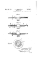
Figure 5 is a diametricalsection through a Wheel embodying our invention in still another form.
Figure 6 is a diametrical section through a `.20 wheel embodying a further modified form.
Figure 7 is a diametrical section through a wheel embodying our invention in substantially the form shown in Fig. 1, but with certain modications, and
Figure 8 is a side plan view of a wheel ac*- cording to Fig. 7 with a part removed.
Generally speaking, our invention consists in the provision of a wheel web composed of one or more resilient disks suitably apertured so as to permit resilient movements of its center portion relative to its rim portion. The disk or disks, of which the web is composed, may be composed of anysuitable material, preferably spring steel. Preferably, and as shown in all the figures of thedrawings, a suitable perforation consists of a spiral slot generated about the rotational axis of the disk. In Figs. 1 and `3, 10 indicates the disk and 11 the spiral slot therein. InV
using such a web in -a vehicle wheel, there would be a tendency under certain conditions for the center portion of the disk'to be forced out of the plane of the rim portion, and consequently means must be provided to take care of such lateral stresses. In Figs. 1 and 3,this means is shown to be a pair of spiders 12 and 13, one at each side of ldisk 10, the spiders and disk 10 being secured at their Acenters to hub flange 14 by means of bolts 15. 'Ihefends of the spider arms extend substantially beyond the outer peripheral limits of slot 11 so as to bear against the rigid rim portion of the disk` at all times. In this manner, all portions of 'disk 10 arealways kept in the same plane. The described elements are so proportioned, however, that radial movements of the hub relative tofelly 16 will never cause the arms of the spiders to abut the felly. If the described web is to be used on a trac- 60 tion wheel, it is desirable to provide means to limit possible rotation of thespiders relative to disk'lO. Consequently, as clearly, shown in Figure 1, we provide the arms of the spiders with enlarged apertures 17 in 65 their ends, and pins 18 iiXed tol'thejsolid rim portion of disk 10 normally extend into the center of these apertures. Abutment of these pins with the wallsof the respective apertures will e'ectively limit rotation ofthe 0 spiders relative to the 4intermediate disk. The size of the apertures relative to that of the pins is such that radial contractions and expansions of the disk are ,not hindered.
Slot 11 is preferably in the form of an 75 Archimedean spiral, and it will be noted that the bounding Walls of the spiral converge at both ends of the latter. Y
Instead of using a spider with solid 4arms to prevent distortion ofthe yslotted disk due 80 to lateral strains, we may .provide several slotted disks side by side as shown in Figs. 2 and 4. According to these figures, spiders 12 and 13 are replaced additional 'slotted disks ,19 and 20, one at eachside of a main slotted disk 10. In this modilication the spirals of disks 19 4and 20 preferably run in .the opposite direction to the spiral of disk 10', that is, if the latter is right hand,the former areboth left hand. Furthermore, the pitch of the spiral slots yin the outer disks differs from that of the inner disk so that the. slots of the three disks will have the least possible coincidence. While we have shown three disks in the figures just referred to, it ist, of course, apparent that the web may comprise any desired number. .According to 5, the web consists of two spaced spirally slot-ted disks 21 and 22, and an intermediate solid disk 23 of suiiicient diameter to extend well within the solid rim portion of each. outer disk, and yet permit adequate radial movement of the hub toward the Jfelly. The center portions of the three disks are all rigidly secured to a hub element.
For heavy duty, the web may be composed j yot a sutliciently massive single disk, or an adequate number ot single disks. The single disk structure may be modified, as illustrated in Fig. 7,`Wherein it will be seen that spiral convolutions 24 of -disk 24 are considerably thickened, and asrhere shown, are substan- Vae vtially diamond shape in cross section. As
means for preventing distortion of the con volutions from normal uniplanar relation,we provide in .this modification cupped rigid plates 25 and 26 rigidly secured at either side of an enlarged central portion 27 ot' the disk.
In Fig. 8, plate 25 has been removed to exposey the convolutions. Y n j Fig. 6 illustrates the use of a central planefaced disk or plate 28 of the same design as disk 10 of Fig. 1, and two outer slotted disks 29 and 30 -whose convolutions are outwardly expanded to give them a substantially triangular cross section as at 31 and 32. The
Y slots ot discs 29 and 80 are of different pitch from that of disc 28, and run in the opposite direction thereto. As indicated in this figure, thel oppositely running slots all start at the left of ther hub. Here, as in Figure 7,
' stitfening means in the form of cupped plates .dei
V33 and 34 are provided, the disks and plates being rigidly secured together at their center portions. The wheel may be made more etfective for traction purposes by providing the margins -ot plates' and 34 with apertures overlying the solid marginal portions yof discs 29 and 30, and pins, as at 29', may be secured to thelatter in position to project through the apertures, the result being the same as described in connection with F ig-f ure 1.
While we have necessarily shown and described'specitic embodiments of our invention, it is clear that many diiferent combinations of elements may be secured Without departing fromv the spirit ot our invention. Accordingly, we do not intend to confine ourselves except as determined in the following claims.
We claim:
' l. rA wheel disk of resilient material, said disk having a single spiral kslot generated about its rotational axis wherebyY radial movements of the center portion of the disk relative to the rim portion are permitted, the
width of the material between adjacent convolutions of the slot being materially greater than the normal width of the slot.
2. A Wheel web comprising a plurality ot coaxially ydisposed resilient disks, each of said disks having a spiral slot generated about the common axis whereby radial movements ofthe center portions of the disks relative to their rim portions are permitted, the slots of adjacent disks being of diii'erent pitch.
3. A wheel disk of resilient material, said disk having a single spiral slot generated about its rotational axis whereby radial movements of the center portion 'of the disk relativel to the rim portion are permitted,
said slot being tapered toward:` its ends, theV width of the materialbetween adjacent convolutions of the slot being materially greater thanv the normal width ot the slot.
4. A wheel disk of resilient material, said Vdisk having a single spiral slot generated about its rotational axis to form spring convolutions intermediate its center portion and rim portion, the Width kot the ymaterial between adjacent convolutions of the slot being materially greater than the normal width of the slot.
5. A wheeldisk of resilient material, said disk having a spiral slot generated about its rotational axis to form spring convolutions intermediate its center portion and rim portion, said convolutions being laterally expanded. f
6. A Wheel disk of resilient material, said disk havinga spiral slot generated` about its rotational axis to form spring convolutionsl intermediate its center portion and rim portion, said convolutions having an integral outwardly tapered lateral extension.
7 A wheel disk of resilient material, said j disk having a spiralslot generated about its rotational axis to form spring convolutions intermediate itscenter'portion and rim portion, said 'convolutions being laterally ex'- panded at both sides. j f
8. Awheel web comprising afplurality of resilient co-axially disposed disks, said' disks each having a spiral slot generated about the common axis to form'spring convolutions inj ate its center portion and rim portion, said portions being respectively securedto said hub and telly, and a plate rigidly secured to said hub lelement intermediate said disks and extending between the rim portions of lthe latter to prevent distortions of the disks from their normal planes while permitting radial distortions of thedisks.
, l0. A traction wheel comprising a resilient "disk, said disk having av vSpiral vslot gener- F. LABB MORENO. DR. R. GLEISNER VERA.
Priority Applications (1)
| Application Number | Priority Date | Filing Date | Title |
|---|---|---|---|
| US218740A US1851640A (en) | 1927-09-10 | 1927-09-10 | Resilient wheel |
Applications Claiming Priority (1)
| Application Number | Priority Date | Filing Date | Title |
|---|---|---|---|
| US218740A US1851640A (en) | 1927-09-10 | 1927-09-10 | Resilient wheel |
Publications (1)
| Publication Number | Publication Date |
|---|---|
| US1851640A true US1851640A (en) | 1932-03-29 |
Family
ID=22816326
Family Applications (1)
| Application Number | Title | Priority Date | Filing Date |
|---|---|---|---|
| US218740A Expired - Lifetime US1851640A (en) | 1927-09-10 | 1927-09-10 | Resilient wheel |
Country Status (1)
| Country | Link |
|---|---|
| US (1) | US1851640A (en) |
-
1927
- 1927-09-10 US US218740A patent/US1851640A/en not_active Expired - Lifetime
Similar Documents
| Publication | Publication Date | Title |
|---|---|---|
| US1851640A (en) | Resilient wheel | |
| US2243380A (en) | Wheel construction | |
| USRE22924E (en) | Disc mounting | |
| US1488824A (en) | Caster wheel | |
| US1383728A (en) | new yobk | |
| US2697467A (en) | Vehicle wheel | |
| US1388910A (en) | Metal wheel | |
| US2059158A (en) | Clutch | |
| US2222393A (en) | Antiskid chain | |
| US1455637A (en) | Wheel | |
| US2245574A (en) | Variable track wheel construction | |
| US1763580A (en) | Wheel for vehicles | |
| US1260655A (en) | Spring vehicle-wheel. | |
| US1366450A (en) | Nellie k howard | |
| US1492068A (en) | Elastic wheel | |
| SU25053A1 (en) | Elastic wheel | |
| US2030076A (en) | Wheel | |
| US1529913A (en) | Spring wheel | |
| SU19936A1 (en) | Elastic wheel tire | |
| US1384783A (en) | seymour | |
| US1370435A (en) | Spring-wheel | |
| US1534934A (en) | Wire-spoke wheel | |
| US1692011A (en) | Resilient wheel | |
| US1438207A (en) | Spring wheel | |
| US1525439A (en) | Tractor wheel |