US1851638A - Railway sleeper and attachment therefor - Google Patents
Railway sleeper and attachment therefor Download PDFInfo
- Publication number
- US1851638A US1851638A US506776A US50677631A US1851638A US 1851638 A US1851638 A US 1851638A US 506776 A US506776 A US 506776A US 50677631 A US50677631 A US 50677631A US 1851638 A US1851638 A US 1851638A
- Authority
- US
- United States
- Prior art keywords
- sleeper
- wings
- section
- rail
- figures
- Prior art date
- Legal status (The legal status is an assumption and is not a legal conclusion. Google has not performed a legal analysis and makes no representation as to the accuracy of the status listed.)
- Expired - Lifetime
Links
- 241001669679 Eleotris Species 0.000 description 44
- 230000015572 biosynthetic process Effects 0.000 description 12
- 238000005755 formation reaction Methods 0.000 description 12
- 229910000831 Steel Inorganic materials 0.000 description 6
- 239000010959 steel Substances 0.000 description 6
- 238000003825 pressing Methods 0.000 description 3
- XEEYBQQBJWHFJM-UHFFFAOYSA-N Iron Chemical compound [Fe] XEEYBQQBJWHFJM-UHFFFAOYSA-N 0.000 description 2
- 239000000835 fiber Substances 0.000 description 2
- 238000009413 insulation Methods 0.000 description 2
- 238000005096 rolling process Methods 0.000 description 2
- 241000251468 Actinopterygii Species 0.000 description 1
- 241000395598 Eleotris sandwicensis Species 0.000 description 1
- 241001517310 Eria Species 0.000 description 1
- 235000004443 Ricinus communis Nutrition 0.000 description 1
- 239000011324 bead Substances 0.000 description 1
- 244000309464 bull Species 0.000 description 1
- 230000001419 dependent effect Effects 0.000 description 1
- 230000000994 depressogenic effect Effects 0.000 description 1
- 238000009408 flooring Methods 0.000 description 1
- 229910052742 iron Inorganic materials 0.000 description 1
- 238000004519 manufacturing process Methods 0.000 description 1
- 238000000034 method Methods 0.000 description 1
- 238000004080 punching Methods 0.000 description 1
- 238000007493 shaping process Methods 0.000 description 1
- 238000003466 welding Methods 0.000 description 1
Images

Classifications
-
- E—FIXED CONSTRUCTIONS
- E01—CONSTRUCTION OF ROADS, RAILWAYS, OR BRIDGES
- E01B—PERMANENT WAY; PERMANENT-WAY TOOLS; MACHINES FOR MAKING RAILWAYS OF ALL KINDS
- E01B3/00—Transverse or longitudinal sleepers; Other means resting directly on the ballastway for supporting rails
- E01B3/16—Transverse or longitudinal sleepers; Other means resting directly on the ballastway for supporting rails made from steel
Definitions
- Such plates or chairs may be secured by any SmSteeI-plate railway sleeper, comprising "a: comparatively deep hollow. " ⁇ l 'section,
Landscapes
- Engineering & Computer Science (AREA)
- Architecture (AREA)
- Civil Engineering (AREA)
- Structural Engineering (AREA)
- Railway Tracks (AREA)
Description
March 29, I c R MAYQ I RAILWAY SLEEPER AND ATTACHMENT THEREFOR //v VENTOB 0L W Filed Jan. 5, 19,31
- C R. MAYO RAILWAY SLEEPER AND ATTACHMENT THEREFOR Filed Jan. 5, 1951 2 Sheets-Sheet 2 March 29, 1932.
I 4/11 M A Ii Patented Mar. 29, 1932 I l UNITED STATES P TENT I bnmns ROBERT MAYO; or LONDONQEN LAND RAiLWAYHSLEEPER AND ATTACHMENT THEREFOR Application "filed Janugry'.5,f.1931,'s eria No'. 506,776, and. 1mm Britain Jen fiery 9, 1930.
This invention comprises improvements "in and connected with railway sleeper's'and atcatchments therefor and has for its principal object to provide animpro'ved form of steel- "regard to "the heavier "into more general use;
7 p late sleeper.
More "specifically one object is t provide a. sleeper of whieh'the seetion, when depressed *by a 1 0ad,tent1s to compact theyballast retaqined 'beneetththe "wings 'QInd with which the ballast is easily paokedowing to the facility with whie'h access is had thereunder, so that it' he'vsleeperean be befldetl withgreat security ex-rid high resistance is'oil'e 'ed to sleeper-creep. A ftrrt ero'bject is toproyide a sleeper whereare very accessible and eanQbe' adjusted- Without disturbing the sleeper or removing-ballast. Yet another objeet is to provide a, steelplate sleeper of adequate strength and stiffness but of very light Weight fol-{a given rail weight or load, this being of importance hay- 1 rails now coming Vafious embodiments of the invention are illustrated 'hywaty of example in the zte'ompan 'ng drawings in which v f igm'esl and 2 are oi'oss sections showing forms*ofsleeper, M I v g Figures 3 anclfi are a sideelev'ation' and plan of a complete sleeper;
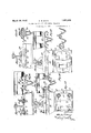
' f Figuresfi and 6erejpeft1sectiondl (51mtions,"at1;ight angles to .eachother, of one erramgement oi? sole platemidclips on a V- sleepe'ii'g I f L Figures '7 and 8 'are similar views of a V secoml such arrangement on a V-sleeper,
g re/wand 10 are similar View f fhi Figures 14, 155*and'16 are yiewseorresponl ing with Figures 1.1913 and showi ig en el-' tei native ch'air arrangement.
' Figures 17e ndl8 are eh elevation ahdfeross section oife'V-sl'eepependchairiike rail'su port, and
Fi'gure lgg is a cross seetion ofeW-shap'ed v-sectionv sleeper in eecortlence with the 'vention The V-sectiojri sleeper l is :foiiii ed withdowntiirnejd wings or extensions Z'atthe 7 sides, said Wings being produced; wheii rolling or pressing :the jv'section frorhthe fist strip, The wings may forexample" be rounded, t
onfthehndeiside and fiagt on the iuppefmside? v (Figure 1) or flat'on both sides (figure-2). Each Winghas a Width; equal to about one? the V. The sleepers mayfbel prod eedeaeh and2end l9,--.0r they may be out from ale'ngth ffi om gtlength of flat steel plate, giviii'g; the v 1 sections shown in dotted lines inFigures.11:1? In the means employedfor'secuymgthe rails of flat steel stripiafterthe latter hasfbeen i'olledto theldesii ea sectioilgjThe plete or};
strip rolled may have ethickeiied ribg along the n'iicldle which in the finished sleeper forilis :1. I
ltheibottoin' of the 'V' end gives greatei" thickit would appear before being rolled up to the v 11ess thei'ei, The;.pletesoi'flstrips may have (thickened portions :14. along itheiifmarg inal patts and such thickened portions niay present surfaees 5 which originally are concaved aboi t a longitudinal axis; Such 'at plate or strip is shown by chain lines in Figure 1 as V-section, After-such ro11ing,the-coi oaVe s surfaces 5 off the thickened portions :4, are i. converted, as shown, into pl'ane surfeees by thebending. Such plane surfaces czuilbe used in the mounting of solepla'tes; ehairs, and
Theplates strips be giyeiizothei'llesirable "sections or 1 local formations for the sleepers are produced from suehplates. or
production of desired sleepe rparts, wherithe 1 strips; The depth, section and shaping ,of
the sleeper initsfinal form willbecalei lated'g tosuit thekihdp fballast to be used, the'iexle loads to be encountered and the'modeof at- 1 ta ehment l of: the Tails by, sole-plates; Chairs end other accessories, or byfftheir direetget itachmegnt to the; sleepers; The edges of; the Win m y e b e t giv is Y Greased strengthfiand to faci-littteLhandling.
Hit is desired toadztpt'the sleeper so that/{it w a e. ca j f' t Tierlding o ben n r at the middle, :i portioii o'fthe depth of they; I can be removed by punching, sheai ih g or'the v fao I 7 like or by means applied during the rolling or pressing of the sleeper. Alternatively the section of the sleeper mayvaryal-o'ng its length,- being for instance of ordinary trough section in the middle and of V-section according to the invention at the rail seats and ends: The ends of the sleeper may be finished as desired. For example the ends may be closed or fish tailed by sloping down the surfaces of the sleeper as in Figures 3'and 4. 7 a Such closure tendstogprevent movem'entlat Verally of the track.
The shape of the sleeper 1 may itself .provide' the necessarybearing surface for the rails; if the crests of the-wings are rounded,
however, they ma'y be local-lyflattened for this Z purpose. Rail engaging lugsrnay be punched 7 n'pfr'om the wings 2 without detriment to themain body of the sleeper 1 and clips j'be secured" in position to :hold the rails by jmeans of bolts engaging -vthe wings2. Such bolts are easily accessible owing to theshallowness of the'wings as comparedwith' the-V of the sleeper;"
1 J Pressed or cast soleiplates' mple width,
1 Alternatively the rails may bear rolled,
welded; riveted, bolted or otherwise attached to the sleepers. This arrangement isj'shown in 'Figuresg and 4 wherein sole plates 6, which extendacross the hollow of the sleeper 1 5mm it "wingtowing thereof, are welded to said wings 2. In' thermodifications' shown in Figures 1 15 10, thefsoleplates 6 are attached to the sleepers by rivets '7; The attachment of the 5 rails maybe accomplished by keys, bolts or f clips. fln Figures 3 6, simple clip plates 8 jean bejca used to gripthefoot'o'f the rail 9 V to t-hesole plate 6 by screwing jdown nuts 10 ion bolts 11 having-squared portions 12 em gaging'square holes 13 in the plate 6." Downward- 'lugs 14" on the clips 8 engage in holes 15 i fin thesoleplate'fl to. preventtwisting of said 4'5 different; clip arrangement is'shown in are substantially S shaped, the upper hook of V ithe' S engaging over the'bottom flange of the frail'9 while the lower hook is forked'jtoen- Figures 7 and-8'. "Inthis'case the clips 16 gagelaround a square port on 12 of the T- 1 p1 6 and bolts 11 canbeeasily placed in'po'sr 9 lv l l and replaced at any time w thout disturbing the, sleeper '1 or V the rail v I or: causing any inconvenience as they a are readily accessible in thehollow of the sleeper. a v
In Figures 9 and 10 the clips are simply robustdished washers 18 having their concaveside downwards so as to have lines of gripping contact on the rail foot and sole.
plate. These clips are caused to grip the rail flange to the plate 6 bytighteningthenuts 10] on thee-bolts 11. Said-bolts have f squared shank portions 19 engaging square holes in the plate 6.-
combinations of the means described. above may "also be employed. "Alternatively sole plates of-castgiron may be cast in position on the sleepers after' the' formation of the For attaching the sole plates to the rail,
latter. 1 Eitherthe sleepers themselves or the Jcant to the rails. Figures r3' and lillustrate a camberedsleeper 1 wherebyrla cantisim; parted to the rail 9 Figures. 5 ;.to :8 show J sole plates 6. designed to .hold jthe, rail 9 perpendicular to the sleeper'l whatever "the disposition of the latter may be., Figures) ,and 10, on the other'hand, illustrate-how ,c'ant may be given to the rail 9 by the use .of a sole plate .6 Which-is. slightly' wedge shaped. ."I he rail instead of being heIdby between clips on the 'insideandlugs or flanges on' the sole )plate' on the outside. Distance pieces gripping the flange of the rail gmay then be employed if desired. v The sleepersaccording to. may also be; employed in conjunction with castor pressed up chairs or chair-plates,
bolted, rivetedor cast thereon. Examplesjof' chair supports for bull headedirails such as are commonly" in use in Great Britain; are illustrated 'in Figures 11-116; Figures 1143 show a" form of chair 20of east iron I or wrought steel] bolted; (alternatively it might be riveted)? by bolts 21' to the wings *2 of the sleeper 1. 1 Insulation 22 in the form the invention sole plates can be shapedto give anyrequired clips on both s; Y tm'ay be held" 6 of fibre shimsand fibre vferrulesand washers f on the bolts is provided for track circuit-mg purposes.- Atransverse,rib'23 cast under- A n'eaththe ch'airj fits in the V of the sleeper ia' ndassists in seouring the ch-air'ffast in position; 111 Figures '1416 the si-milarjohair ..20.is: secured to the sleeper 1 dependent lugs 24 cast in position so asto project down :through holes in'fthe wings 2, of the-sleeper.
lis-
. What has been said above regarding the'cant- 2 ing of therail when sole 'plateslareg usedis 7 equally. applicable tothese chairplates.
A .a ra s en emp eyi a supp t 2 partaking of s m of the characteristics of both sole plate "and chair isillustrated) in Figures 1'7'and 18. The;-rail; shown, which is o'f theffoOt .flan g type, is held byits foot 5 fia'ngebetween two shaped keys 26., 27 wedged between said 'foot flange and upstanding re-' cessedlugs 280 11] the support, 25., Saidsupa port 25 is'caston' the sleeper 1, beingformed W -hr b2-9w e fi n eYPf he eep r "harness V I3 and with four lugs 30 cast to projectlaterally through holes in the sides of the V.
An example of a W-section for a sleeper according to this invention is illustrated in Figure 19. As will be seen the section is virtually composed of two V sections 1. The wings 2 and central crest 31 being rounded,
, flats 32 areprovided at the seats or points of attachment of the seating plates or chairs.
of the methods described, for instance riveting may be employed at the central crest and welding at the wings; W ormulti-V forms of sleeper are particularly applicable for use at rail joints, points and crossings. In yards or other places the V or W sleepers can be laid closely alongside one another in such a fashion as not only to support the track but also to 'form the yard or other flooring. What I claim is 7 1. Steel-plate railway sleeper, of comparatively deep hollow V-section comprising inclined sides meeting in an apex ridge and wings of inverted trough formation extending outwardly from the top lateral edges of the sides and of considerably less depth than a ing a comparatively deep-hollow V-section, 1
wings of inverted troughformation extenda r ing outwardly from the top lateral edges of' the section, chairs attached to said wings so .as to bridge the V-s-ection, and abutments said sides. V
'2. Steel-plate railway sleeper, of comparativelydeep hollow V-sectionflcomprising inclined'sides meeting in an apex ridge, wings of inverted trough formation extending outwardly from the top lateral edges of the sides and of considerably less depth than said sides and bearing-flats provided on said wings.
3. Steel-plate railway sleeper, of comparatively deep hollow V-section comprising inclined sides meetingin an apex ridge, wings of inverted trough formation extending outwardly from the top lateral'edges of the sides and of considerably'less depth than said sides and rail supportsattached to said wings was to bridge the V-section.
4. Steel-plate railway sleeper, of comparatively deep hollow V-section comprising inclined sides meeting in an apex ridge, wings of inverted trough formation eXtend-.
ing outwardly from the top lateral edges of the sides and of considerably less depth than said sides, sole plates attached to said wings device having an intermediate fulcrum point of bearing under the sole plate, one arm of said lever being adapted for pressing down upon and grippmg the rall-flange,and'securing means such as a bolt device for applying 7 upward pressure to the other arm of said lever. V
6. Steel-plate railway sleeper, comprising a comparatively deep hollow V-section,
wings of inverted trough f0rmation-.eXtend-- wings :of inverted trough formationextend? ing outwardly from the'top lateral edges of the section,.. and ab'utments formed on'the' isleepertotake up lateral thrust of the rails. Such plates or chairs may be secured by any SmSteeI-plate railway sleeper, comprising "a: comparatively deep hollow. "\l 'section,
wings of inverted troughforination extending-,outwardlyfrom the top lateral edges of thesectiomsole plates attached to said wings so as to bridge the V-section, and abutments formed on the sole plates to take up lateral r thrust of the rails.
9. Steel-plate railway sleeper, comprising a the section, sole plates attached to said wings so as to bridge the V-section, and abutments formed on said sole platesfor engaging said sleeper.
form-ed on said chairs for engaging said sleeper. r a
11. Steel plate railway-sleeper, comprising a comparatively deep hollow multiple V section and wings of inverted trough forma tion extending outwardly from the top lat eral edges of the section. 7
12. Steel plate railway sleeper, comprising I a comparatively deep hollow multiple V-sec-- tion, wings of inverted trough formation extending outwardly from the top lateral edges of the section, andbearing-fiats provided on said section and wings. a
10. Steel-plate railway sleeper, compris-' a comparatively deep hollow multipleV-section', wings of inverted trough formation eirtending outwardly from the top lateral edges of the section, and sole plates attached to said wings so as to bridge said multiple V-section. so as to bridge the V-sectlon, and clip de- 14. Steel-plate railway sleeper, comprising a comparatively deep hollow V-section, w'ings of inverted trough formation extending outwardly from the top lateral edges of the sec- 1 tion, and a stiffening rib along the base of the "ii-section.
15. Steel-plate railway sleeper, comprising acomparatively deep hollow V-section,
wings of invertedtrough formation extending; outwardly from the-,top'lateral "edges ofthe section, and beads provided along the L edges of said wings. r
16; Steel-plate railway sleeper, comprising I a comparatively deep hollow V-section, wings of invertedtrough formationextending out-Q wardly from the top lateral edgesiof' the seeti0n,;.1:ail supports secured to said Wingsand. insulation separating said'supports from said Zsleeper J 17 Steel fJIate sleeper 61 flaiiged rails, V comprising a comparatively deep hollow V- section, ivingsof inverted trough formation j extending outwardly, from v the, top: lateral edges of 'thelsection, sole plates attached to said Wings so as to bridge the 'V-section, up-
standing-recessed'lugs on said sole plates, and shaped keys adapted for fbeing wedged between the ra-il'flanges and said recessedlflgs CHARLES ROBERT MAY
Applications Claiming Priority (1)
| Application Number | Priority Date | Filing Date | Title |
|---|---|---|---|
| GB1851638X | 1930-01-09 |
Publications (1)
| Publication Number | Publication Date |
|---|---|
| US1851638A true US1851638A (en) | 1932-03-29 |
Family
ID=10891976
Family Applications (1)
| Application Number | Title | Priority Date | Filing Date |
|---|---|---|---|
| US506776A Expired - Lifetime US1851638A (en) | 1930-01-09 | 1931-01-05 | Railway sleeper and attachment therefor |
Country Status (1)
| Country | Link |
|---|---|
| US (1) | US1851638A (en) |
Cited By (2)
| Publication number | Priority date | Publication date | Assignee | Title |
|---|---|---|---|---|
| US4511081A (en) * | 1982-01-21 | 1985-04-16 | The Broken Hill Proprietary Company Limited | Rail anchoring clip and associated sleeper |
| US4583685A (en) * | 1982-12-06 | 1986-04-22 | The Broken Hill Proprietary Company Limited | Rail anchoring |
-
1931
- 1931-01-05 US US506776A patent/US1851638A/en not_active Expired - Lifetime
Cited By (2)
| Publication number | Priority date | Publication date | Assignee | Title |
|---|---|---|---|---|
| US4511081A (en) * | 1982-01-21 | 1985-04-16 | The Broken Hill Proprietary Company Limited | Rail anchoring clip and associated sleeper |
| US4583685A (en) * | 1982-12-06 | 1986-04-22 | The Broken Hill Proprietary Company Limited | Rail anchoring |
Similar Documents
| Publication | Publication Date | Title |
|---|---|---|
| US2828080A (en) | Railroad crossing structure | |
| US1851638A (en) | Railway sleeper and attachment therefor | |
| US1559965A (en) | Automatic safety bumper | |
| US1743924A (en) | Track crossover for railroads | |
| US2839249A (en) | Railroad track crossing | |
| US182627A (en) | Improvement in railroad-rail joints | |
| US1590071A (en) | Toy railroad bridge | |
| US1752451A (en) | Base plate for railroad-track structures | |
| US2703205A (en) | Rail joint assembly | |
| US1743598A (en) | Railway track structure | |
| US1252647A (en) | Railway-track structure and method of making same. | |
| US1711880A (en) | Rail joint | |
| US2047007A (en) | Continuous rail | |
| US1574754A (en) | Method of making pavement conformation | |
| US1546118A (en) | Floor-trough structure for bridges | |
| US1694811A (en) | Railway roadbed and track construction | |
| US2196521A (en) | Rail fastening | |
| US1507870A (en) | Railway rail | |
| US1639960A (en) | Anticreeping joint | |
| US1814548A (en) | Plate support for rail joints | |
| US1613498A (en) | Rail or rolled member | |
| US1720372A (en) | Bar plate or rail-joint bar | |
| US2087224A (en) | Adjustable rail brace | |
| US1487432A (en) | Rail-securing means | |
| US1489064A (en) | Fishplate |