US1851632A - Reel for winding yarn - Google Patents
Reel for winding yarn Download PDFInfo
- Publication number
- US1851632A US1851632A US439806A US43980630A US1851632A US 1851632 A US1851632 A US 1851632A US 439806 A US439806 A US 439806A US 43980630 A US43980630 A US 43980630A US 1851632 A US1851632 A US 1851632A
- Authority
- US
- United States
- Prior art keywords
- reel
- tubular shaft
- collars
- rod
- adjusting rod
- Prior art date
- Legal status (The legal status is an assumption and is not a legal conclusion. Google has not performed a legal analysis and makes no representation as to the accuracy of the status listed.)
- Expired - Lifetime
Links
- 238000004804 winding Methods 0.000 title description 9
- POIUWJQBRNEFGX-XAMSXPGMSA-N cathelicidin Chemical compound C([C@@H](C(=O)N[C@@H](CCCNC(N)=N)C(=O)N[C@@H](CCCCN)C(=O)N[C@@H](CO)C(=O)N[C@@H](CCCCN)C(=O)N[C@@H](CCC(O)=O)C(=O)N[C@@H](CCCCN)C(=O)N[C@@H]([C@@H](C)CC)C(=O)NCC(=O)N[C@@H](CCCCN)C(=O)N[C@@H](CCC(O)=O)C(=O)N[C@@H](CC=1C=CC=CC=1)C(=O)N[C@@H](CCCCN)C(=O)N[C@@H](CCCNC(N)=N)C(=O)N[C@@H]([C@@H](C)CC)C(=O)N[C@@H](C(C)C)C(=O)N[C@@H](CCC(N)=O)C(=O)N[C@@H](CCCNC(N)=N)C(=O)N[C@@H]([C@@H](C)CC)C(=O)N[C@@H](CCCCN)C(=O)N[C@@H](CC(O)=O)C(=O)N[C@@H](CC=1C=CC=CC=1)C(=O)N[C@@H](CC(C)C)C(=O)N[C@@H](CCCNC(N)=N)C(=O)N[C@@H](CC(N)=O)C(=O)N[C@@H](CC(C)C)C(=O)N[C@@H](C(C)C)C(=O)N1[C@@H](CCC1)C(=O)N[C@@H](CCCNC(N)=N)C(=O)N[C@@H]([C@@H](C)O)C(=O)N[C@@H](CCC(O)=O)C(=O)N[C@@H](CO)C(O)=O)NC(=O)[C@H](CC=1C=CC=CC=1)NC(=O)[C@H](CC(O)=O)NC(=O)CNC(=O)[C@H](CC(C)C)NC(=O)[C@@H](N)CC(C)C)C1=CC=CC=C1 POIUWJQBRNEFGX-XAMSXPGMSA-N 0.000 description 5
- 230000000153 supplemental effect Effects 0.000 description 5
- YOCIJWAHRAJQFT-UHFFFAOYSA-N 2-bromo-2-methylpropanoyl bromide Chemical compound CC(C)(Br)C(Br)=O YOCIJWAHRAJQFT-UHFFFAOYSA-N 0.000 description 1
- 230000008878 coupling Effects 0.000 description 1
- 238000010168 coupling process Methods 0.000 description 1
- 238000005859 coupling reaction Methods 0.000 description 1
- 238000004519 manufacturing process Methods 0.000 description 1
- 229940025656 proin Drugs 0.000 description 1
- 230000001105 regulatory effect Effects 0.000 description 1
Images
Classifications
-
- B—PERFORMING OPERATIONS; TRANSPORTING
- B65—CONVEYING; PACKING; STORING; HANDLING THIN OR FILAMENTARY MATERIAL
- B65H—HANDLING THIN OR FILAMENTARY MATERIAL, e.g. SHEETS, WEBS, CABLES
- B65H49/00—Unwinding or paying-out filamentary material; Supporting, storing or transporting packages from which filamentary material is to be withdrawn or paid-out
- B65H49/18—Methods or apparatus in which packages rotate
- B65H49/20—Package-supporting devices
- B65H49/30—Swifts or skein holders
-
- B—PERFORMING OPERATIONS; TRANSPORTING
- B65—CONVEYING; PACKING; STORING; HANDLING THIN OR FILAMENTARY MATERIAL
- B65H—HANDLING THIN OR FILAMENTARY MATERIAL, e.g. SHEETS, WEBS, CABLES
- B65H2701/00—Handled material; Storage means
- B65H2701/30—Handled filamentary material
- B65H2701/31—Textiles threads or artificial strands of filaments
Definitions
- This invention relates to improvements in reels of that type which are employed for Winding yarn in skeins for mill use. It has for its object the provision of means whereby the diameter of the reel can be adjusted so that skeins of difierent sizes can be wound to meet different requirements and so that the diameter of a wound reel can be reduced to facilitate the removal of the skeins.
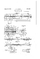
- Figure 1 is a side elevation bodying the invention
- Figures 2 and 3 are elevations of the re- 'spective ends of the reel.
- Figure l' is a detail view, broken away in parts, showing the rod and nuts threaded thereon for adjusting the arms of the reel to vary the diameter thereof.
- Figure 5- is a similar view showing the tubular shaft on which are mounted the opera,- tive parts. 7
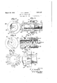
- FIGS 6-8 are detail views showing the adjustable coupling means between the tubular shaft and the threaded rod.
- Figure 9 is an enlarged sectional view of the nut for transmitting the movement of the adjusting rod to the slide carrying the reel arm.
- FIGS 10-11 are detail views, showing the slide on the tubular shaft to which are pivoted the arms of the reel.
- Figure 12 is a longitudinal sectional view, showing the connection between the slide, nut and adjusting rod.
- 15 designates a suitable supporting frame for the reel.
- the tubular shaft 16 mounted between the ends of the frame is the tubular shaft 16, through which extends the adjusting rod 17.
- the ends of the adjusting rod pass through the caps 18 and 19, respectively attached to the ends of the tubular shaft, the caps holding the rod in axial, relation to the tubular shaft.
- the outerends of the caps 18 and 19 are cylinof a reel emthe cap 19 is the drical and, respectively, form bearings 45. and 47, which are journaled in the frame ends, providing the rotatable mounting for i the reel in the frame.
- supplemental nut 31 also engaging the screwthread engaged by theadjacent main nut.
- the supplemental nut is adjusted with relation to the main nut by means of the opposite pins 32 threaded through the supplemental nut and engaging'the main nut. Between the opposite holding pins 32 are the opposite V set-pins 33 threaded through the supplemental nut andimpinging on the main nut. As the threaded engagement between the nuts and adjusting rod becomes worn, lost motion between the nuts and rod can be taken by adjusting the supplemental nut with relation to the'main nut by manipulating the pins 32 and 33.
- On an intermediate part of the adjusting rod 17 is secured the bushing 34 fitting the bore of the tubular shaft. This bushing and the nuts 27 and 31 maintain the intermediate part' of the adjusting rod in axial relation to the tubular shaft.
- the movement of the two pairs of collars is inward from the position shown in Figure 1, the arms 23 aremoved to lessen the diameter of the reel.
- the inner collars 22 are not provided with directly-acting propelling nuts, but each is provided with a single guiding bolt, similar to the guiding bolt 29 that travels in a slot in the tubular shaft 16, such a slot being indica ted by dotted lines at on Figure 5.
- Means are provided for holding the adj ustfing rod 26 in its adjustments in the tubular shaft 17 for regulating the diameter of the reel.
- Figures 58. s
- the rod 26 projects through a rectangular opening 36 in the head of the cap 18 and is shaped, as at 37, to fit the opening so that relative turning movement of the rod and cap is prevented.”
- the cap is provided with a flange 38, through the opposite sides of which extend a series of openings 39. In assembled posit-ion, the flange 38 abuts the opposite flange 40 of the annular member 41 seated in the adjacent end of the tubular shaft.
- On the inner face of the annular member are lugs 42 engaging similarly shaped recesses in the end of the tubular shaft.
- the bolts 44 are withdrawn to free the cap 18 from the tubular shaft.
- the rod 17 is turned by a suitable. tool engaging.
- Means are provided to facilitate theremoval of the wound skeins.
- One of the ends of the supportingframe 15, as at 48, consists of two parts hinged together at49 sothat the upper part, canbe turned outwardlyto free the end ofthe tubular shaft and adjusting rod. 7
- a catch 50 is provided for holding the upper endpart in uprightposition.
- a shaft 51 is; journaled across the lower part of the frame 15 and fixed on an intermediate of the shaft is the arm 52- jSecuredon anfend of the shaft is a lever 53 forturningjthe shaft.
- a supporting-frame with a tubular shaft rotatably mounted in thesup porting frame, an adjustingrod rotatable in v the tubular shaft,- opposite nuts within the tubular shaft respectively engaging right and left screw-threads of the adjusting rod, collars slidable on the tubular shaft, means connecting each collar with one of the nuts so that rotation of the adjusting rod causes travel of the collars toward and from each other according to the direction in which the rod is turned, a reel for supporting the skeins including a plurality of longitudinal slats flush with the periphery of the reel, and opposite arms contained within the periphery of the reel and hinged to each slat and respectively pivoted to the collarsso that movement of said collars varies the radial distance between the slat and the tubular shaft, the adjustment of the slats operating to vary the diameter of the reel, the lessening of the diameter of the reel loosening the skeins wound thereon to be moved clear of the reel
- a reel for winding yarn in skeins the combination of a supporting frame, with a tubular shaft rotatably mounted in the supporting frame and having elongated slots in its wall, an adjusting rod rotatable in the tubular shaft, opposite nuts within the tubular shaft respectively engaging right and left screw-threads of the adjusting rod, collars slidable on the tubular shaft, a bolt connecting each collar with one of the nuts and extending through one of the slots in the tubular shaft so that rotation of the adjusting rod causes travel of the collars toward and from each other according to the direction in which the rod is turned, a reel for holding the skeins including a plurality of longitudinal slats flush with theperiphery of the reel, and opposite arms contained within the reel and hinged to each slat and respectively pivoted to the collars so that movement of said collars varies the radial distance between the slat and the tubular shaft, the inward adjustment of the slats operating to lessen the diameter of the reel
- a reel for winding yarn in skeins the combination of a supporting frame, with a tubular shaft rotatably mounted in the supporting frame, an adjusting rod rotatable in the tubular shaft, opposite nuts within the tubularshaft respectively engaging right and left screw-threads of the adjusting rod, collars slidable on the tubular shaft, means for connecting each collar with one of the nuts so that rotation of the adjusting rod causes the travel of the collars toward and from within the tubular shaft respectively engage ing right andleft screw-threads of the adjusting rod, means for connecting one of the collars of each pair with one of the nuts so that rotation of the adjusting rod causes travel of the pairs of collars toward and from each other according to the direction of rotation of the adjusting rod, a reel for holding the skeins including a pluralityof longitudinal slats flush with, the periphery of the reel, and arms contained within the reel and hingedto each slat and pivoted to the collars of both pairs so that relative movement of,
- the pairs of collars turns the arms to vary the radial distance between the slats and the tubular shaft, the lessening of the diameter of the reel operating to loosen the skeins wound thereon to be moved clear of the reel.
Landscapes
- Storage Of Web-Like Or Filamentary Materials (AREA)
Description
March 29, 1932. QCIJORDAN 4 1,851,632
REEL FOR WINDING YARN Filed March 28, 1930 2 Sheets-Sheet l IN V EN TOR.'
6'. 6. efafldam BY A TTORNEY March 29, 1932. c, JORDAN 1,851,632
REEL FOR WINDING YARN Filed March 28, 1930 2 Sheets-$heet 2 I N V EN TOR.
A TTORNEY Patented Mar. 29, 1932 UNITED STATES PATENT OFFICE CARL CATT'ES JORDAN, OF PORTER-DALE, GEORGIA, ASSIGNOR T BIBB MANUFACTUR- ING COMPANY, OF MACON, GEORGIA, A CORPORATION OF GEORGIA REEL FOR WINDING YARN Application filed March 28, 1930. Serial No. 439,806.
This invention relates to improvements in reels of that type which are employed for Winding yarn in skeins for mill use. It has for its object the provision of means whereby the diameter of the reel can be adjusted so that skeins of difierent sizes can be wound to meet different requirements and so that the diameter of a wound reel can be reduced to facilitate the removal of the skeins. The
IOmeans employed for the purpose are de scribed in detail hereinafter, pointed out in the appended claims and illustrated by the accompanying drawings.
Inthe accompanying drawings, in which corresponding reference characters designate corresponding parts,
Figure 1 is a side elevation bodying the invention; Figures 2 and 3 are elevations of the re- 'spective ends of the reel.
Figure l'is a detail view, broken away in parts, showing the rod and nuts threaded thereon for adjusting the arms of the reel to vary the diameter thereof.
Figure 5- is a similar view showing the tubular shaft on which are mounted the opera,- tive parts. 7
Figures 6-8 are detail views showing the adjustable coupling means between the tubular shaft and the threaded rod.
Figure 9 is an enlarged sectional view of the nut for transmitting the movement of the adjusting rod to the slide carrying the reel arm.
Figures 10-11 are detail views, showing the slide on the tubular shaft to which are pivoted the arms of the reel.
Figure 12 is a longitudinal sectional view, showing the connection between the slide, nut and adjusting rod.
Referring to the drawings in detail, 15 designates a suitable supporting frame for the reel. Mounted between the ends of the frame is the tubular shaft 16, through which extends the adjusting rod 17. The ends of the adjusting rod pass through the caps 18 and 19, respectively attached to the ends of the tubular shaft, the caps holding the rod in axial, relation to the tubular shaft. The outerends of the caps 18 and 19 are cylinof a reel emthe cap 19 is the drical and, respectively, form bearings 45. and 47, which are journaled in the frame ends, providing the rotatable mounting for i the reel in the frame. On the outer end of pulley 20 for rotating the combined tubular shaft and rod during a the two collars in spaced relation, so that when either collar of a coupled pair is moved longitudinally on the shaft there is a corresponding movement of the other collarlof the pair. On the ends of the adjusting rod 17 are the oppositely turned screW-threads26, each of which engages a main nut 27 fitting the bore ofthe tubular shaft'16. In the wall of the tubular shaft, adjacent to the travel of each nut, are the opposite longitudinal slots 28. Through these slots extend .the bolts 29 threaded through the adjacentslide collar 21 and engaging at their inner ends the opposite sockets 30 in the adjacent main nut 27. At an endof each main nut 27 .is a
shaft, but the bolts 29 passing through slots prevent rotation of the collar on the shaft. As each of the end collars 21 is moved, there is a correspondingzmovement of its companion. collar 22, as the two collars are coupled y the drawings, vide the maximum diameter the parts are adjusted to proin the reel. If
the movement of the two pairs of collars is inward from the position shown in Figure 1, the arms 23 aremoved to lessen the diameter of the reel. It is to be observed that the inner collars 22 are not provided with directly-acting propelling nuts, but each is provided with a single guiding bolt, similar to the guiding bolt 29 that travels in a slot in the tubular shaft 16, such a slot being indica ted by dotted lines at on Figure 5.
These slots 35 are on opposite sides of the tubular shaft and the bolts engaging with same serve to prevent turning of the collars 22gon the shaft.
Means are provided for holding the adj ustfing rod 26 in its adjustments in the tubular shaft 17 for regulating the diameter of the reel. (Figures 58.) s The rod 26 projects through a rectangular opening 36 in the head of the cap 18 and is shaped, as at 37, to fit the opening so that relative turning movement of the rod and cap is prevented." The cap is provided with a flange 38, through the opposite sides of which extend a series of openings 39. In assembled posit-ion, the flange 38 abuts the opposite flange 40 of the annular member 41 seated in the adjacent end of the tubular shaft. On the inner face of the annular member are lugs 42 engaging similarly shaped recesses in the end of the tubular shaft. This engagement between the: two parts holds the annular member against turning on the tubular shaft. In the flange 40 of the annular member are the diametrically-opposite holes '43 to register with the holes 39 in the flange 38 of the cap 18. Bolts 44 passing through registering openings 39 and43'of the abutting flanges 38 and 40 hold the cap 18 in adjusted relation to the tubular shaft 16. With the cap secured to the tubularshaft,the adjusting rod 17 is held against turning in the tubular shaft by the engagement of its rectangular part 37 with the similarly shaped opening 36 in the'head of the cap. The end of the rod projects beyond the the rods 25. As shown in Figure 1 of cap and is shaped to form the rectangular nib 46 to be engaged by a wrench for turning the rod. The bearings 45 and 47 journaled in the frame of the machine provide the rotatable mounting for the reel.
In adjusting the diameter of thevreel to meet the requirements foritheskeins'to be wound, the bolts 44 are withdrawn to free the cap 18 from the tubular shaft. The rod 17 is turned by a suitable. tool engaging. the
nib46 and this turning" ofthe rod, through the threaded. engagement therewith, moves the nuts 27- toward or from each other to adjust the arms 23 to provide the required diameter of the reel. The turning of the adjusting rod also turns the cap 18 relative- 1y to the annular member 40 and when the.
rodis turned sufficiently to provide there quired diameter for the reel, the 'flanges as gether, the reel will beheldto the required diameter during the windingoperation.
Means are provided to facilitate theremoval of the wound skeins. One of the ends of the supportingframe 15, as at 48, consists of two parts hinged together at49 sothat the upper part, canbe turned outwardlyto free the end ofthe tubular shaft and adjusting rod. 7 A catch 50 is provided for holding the upper endpart in uprightposition. A shaft 51 is; journaled across the lower part of the frame 15 and fixed on an intermediate of the shaft is the arm 52- jSecuredon anfend of the shaft is a lever 53 forturningjthe shaft. When the shaft is turned to position the parts as indicated by dotted lines-in Figure 1, the arm 53 engagesthe underside of the V tubular shaft 16 andsupports the samewhile the upper part of the frame end is turned backon the pivot49 to free the end; of the reel.' With the parts so positioned, 'skeins that have been moved to the end of the reel past the raised armi52. can be removed from' the reel. It is tobe observed that the periphery of the reel is free from obstruction, so that the wound skeins can be easilyslid along thereel and removed when the diameter of the reel is lessened after a. winding o era.
tion. 3 v
What I claim. is, 1 r 1. In a reel for winding yarn in'skeins,
the combination of a supporting-frame, with a tubular shaft rotatably mounted in thesup porting frame, an adjustingrod rotatable in v the tubular shaft,- opposite nuts within the tubular shaft respectively engaging right and left screw-threads of the adjusting rod, collars slidable on the tubular shaft, means connecting each collar with one of the nuts so that rotation of the adjusting rod causes travel of the collars toward and from each other according to the direction in which the rod is turned, a reel for supporting the skeins including a plurality of longitudinal slats flush with the periphery of the reel, and opposite arms contained within the periphery of the reel and hinged to each slat and respectively pivoted to the collarsso that movement of said collars varies the radial distance between the slat and the tubular shaft, the adjustment of the slats operating to vary the diameter of the reel, the lessening of the diameter of the reel loosening the skeins wound thereon to be moved clear of the reel.
2. In a reel for winding yarn in skeins, the combination of a supporting frame, with a tubular shaft rotatably mounted in the supporting frame and having elongated slots in its wall, an adjusting rod rotatable in the tubular shaft, opposite nuts within the tubular shaft respectively engaging right and left screw-threads of the adjusting rod, collars slidable on the tubular shaft, a bolt connecting each collar with one of the nuts and extending through one of the slots in the tubular shaft so that rotation of the adjusting rod causes travel of the collars toward and from each other according to the direction in which the rod is turned, a reel for holding the skeins including a plurality of longitudinal slats flush with theperiphery of the reel, and opposite arms contained within the reel and hinged to each slat and respectively pivoted to the collars so that movement of said collars varies the radial distance between the slat and the tubular shaft, the inward adjustment of the slats operating to lessen the diameter of the reel to permit the withdrawal of the wound skeins from the reel.
3. In a reel for winding yarn in skeins, the combination of a supporting frame, with a tubular shaft rotatably mounted in the supporting frame, an adjusting rod rotatable in the tubular shaft, opposite nuts within the tubularshaft respectively engaging right and left screw-threads of the adjusting rod, collars slidable on the tubular shaft, means for connecting each collar with one of the nuts so that rotation of the adjusting rod causes the travel of the collars toward and from within the tubular shaft respectively engage ing right andleft screw-threads of the adjusting rod, means for connecting one of the collars of each pair with one of the nuts so that rotation of the adjusting rod causes travel of the pairs of collars toward and from each other according to the direction of rotation of the adjusting rod, a reel for holding the skeins including a pluralityof longitudinal slats flush with, the periphery of the reel, and arms contained within the reel and hingedto each slat and pivoted to the collars of both pairs so that relative movement of,
the pairs of collars turns the arms to vary the radial distance between the slats and the tubular shaft, the lessening of the diameter of the reel operating to loosen the skeins wound thereon to be moved clear of the reel.
In testimony whereof I aflix my signature.
CARL OATTES JORDAN.
each other according to the direction in which the rod is turned, means for locking the rod to the tubular shaft to hold the rod in its rotatable adjustments, a reel for holding the skeins including a plurality of longitudinal slats flush with the periphery of the reel, and
opposite arms contained in the reel and hinged to each slat and respectively pivoted to the collars so that the movement of said collars varies the radial distance between the
Priority Applications (1)
| Application Number | Priority Date | Filing Date | Title |
|---|---|---|---|
| US439806A US1851632A (en) | 1930-03-28 | 1930-03-28 | Reel for winding yarn |
Applications Claiming Priority (1)
| Application Number | Priority Date | Filing Date | Title |
|---|---|---|---|
| US439806A US1851632A (en) | 1930-03-28 | 1930-03-28 | Reel for winding yarn |
Publications (1)
| Publication Number | Publication Date |
|---|---|
| US1851632A true US1851632A (en) | 1932-03-29 |
Family
ID=23746203
Family Applications (1)
| Application Number | Title | Priority Date | Filing Date |
|---|---|---|---|
| US439806A Expired - Lifetime US1851632A (en) | 1930-03-28 | 1930-03-28 | Reel for winding yarn |
Country Status (1)
| Country | Link |
|---|---|
| US (1) | US1851632A (en) |
Cited By (2)
| Publication number | Priority date | Publication date | Assignee | Title |
|---|---|---|---|---|
| DE1179490B (en) * | 1958-07-21 | 1964-10-08 | Croon & Lucke G M B H Maschine | Reel machine |
| DE1197717B (en) * | 1958-01-23 | 1965-07-29 | Achenbach Soehne Ges Mit Besch | Spreader shaft for stretching wrapped bands |
-
1930
- 1930-03-28 US US439806A patent/US1851632A/en not_active Expired - Lifetime
Cited By (2)
| Publication number | Priority date | Publication date | Assignee | Title |
|---|---|---|---|---|
| DE1197717B (en) * | 1958-01-23 | 1965-07-29 | Achenbach Soehne Ges Mit Besch | Spreader shaft for stretching wrapped bands |
| DE1179490B (en) * | 1958-07-21 | 1964-10-08 | Croon & Lucke G M B H Maschine | Reel machine |
Similar Documents
| Publication | Publication Date | Title |
|---|---|---|
| US2682924A (en) | Expansible and collapsible mandrel | |
| US1186226A (en) | Spraying device. | |
| US1851632A (en) | Reel for winding yarn | |
| US1778258A (en) | Journal box | |
| US1748174A (en) | Spindle bearing | |
| US1426764A (en) | Crane | |
| US2244333A (en) | Apparatus fob the production of | |
| US2971399A (en) | Telescopic protector | |
| US1951715A (en) | Uniform speed reel | |
| US1484045A (en) | Top roll for spinning frames | |
| US3321152A (en) | Yarn package stand | |
| US720141A (en) | Ribbon-winder. | |
| US2132834A (en) | Tire building form | |
| US3452941A (en) | Mandrel assembly for winding machines | |
| US1055576A (en) | Spindle for stock-rolls. | |
| US1518428A (en) | Paper-rolling machine | |
| US2148065A (en) | Reel support | |
| US2534515A (en) | Circumferentially traveling support mounted, tire mounting apparatus | |
| US1870954A (en) | Adjustable cake holder | |
| US2190597A (en) | Measuring device | |
| US2294653A (en) | Wire coiling machine | |
| US1677358A (en) | Temper screw | |
| US656264A (en) | Skein-holder. | |
| US1791890A (en) | Winding machine | |
| US2041214A (en) | Skein-forming device |