US1851628A - Roulette golf - Google Patents
Roulette golf Download PDFInfo
- Publication number
- US1851628A US1851628A US546634A US54663431A US1851628A US 1851628 A US1851628 A US 1851628A US 546634 A US546634 A US 546634A US 54663431 A US54663431 A US 54663431A US 1851628 A US1851628 A US 1851628A
- Authority
- US
- United States
- Prior art keywords
- ball
- wheel
- roulette
- golf
- motor
- Prior art date
- Legal status (The legal status is an assumption and is not a legal conclusion. Google has not performed a legal analysis and makes no representation as to the accuracy of the status listed.)
- Expired - Lifetime
Links
- QSHDDOUJBYECFT-UHFFFAOYSA-N mercury Chemical compound [Hg] QSHDDOUJBYECFT-UHFFFAOYSA-N 0.000 description 5
- 229910052753 mercury Inorganic materials 0.000 description 5
- 230000000994 depressogenic effect Effects 0.000 description 2
- 230000005484 gravity Effects 0.000 description 2
- 241000364021 Tulsa Species 0.000 description 1
- 238000010276 construction Methods 0.000 description 1
- 230000004048 modification Effects 0.000 description 1
- 238000012986 modification Methods 0.000 description 1
Images

Classifications
-
- A—HUMAN NECESSITIES
- A63—SPORTS; GAMES; AMUSEMENTS
- A63F—CARD, BOARD, OR ROULETTE GAMES; INDOOR GAMES USING SMALL MOVING PLAYING BODIES; VIDEO GAMES; GAMES NOT OTHERWISE PROVIDED FOR
- A63F7/00—Indoor games using small moving playing bodies, e.g. balls, discs or blocks
- A63F7/06—Games simulating outdoor ball games, e.g. hockey or football
- A63F7/0604—Type of ball game
- A63F7/0628—Golf
-
- A—HUMAN NECESSITIES
- A63—SPORTS; GAMES; AMUSEMENTS
- A63F—CARD, BOARD, OR ROULETTE GAMES; INDOOR GAMES USING SMALL MOVING PLAYING BODIES; VIDEO GAMES; GAMES NOT OTHERWISE PROVIDED FOR
- A63F5/00—Roulette games
- A63F5/02—Roulette-like ball games
-
- A—HUMAN NECESSITIES
- A63—SPORTS; GAMES; AMUSEMENTS
- A63F—CARD, BOARD, OR ROULETTE GAMES; INDOOR GAMES USING SMALL MOVING PLAYING BODIES; VIDEO GAMES; GAMES NOT OTHERWISE PROVIDED FOR
- A63F9/00—Games not otherwise provided for
- A63F9/24—Electric games; Games using electronic circuits not otherwise provided for
- A63F2009/2448—Output devices
- A63F2009/245—Output devices visual
- A63F2009/2451—Output devices visual using illumination, e.g. with lamps
-
- A—HUMAN NECESSITIES
- A63—SPORTS; GAMES; AMUSEMENTS
- A63F—CARD, BOARD, OR ROULETTE GAMES; INDOOR GAMES USING SMALL MOVING PLAYING BODIES; VIDEO GAMES; GAMES NOT OTHERWISE PROVIDED FOR
- A63F5/00—Roulette games
- A63F5/0011—Systems for braking, arresting, halting or stopping
-
- A—HUMAN NECESSITIES
- A63—SPORTS; GAMES; AMUSEMENTS
- A63F—CARD, BOARD, OR ROULETTE GAMES; INDOOR GAMES USING SMALL MOVING PLAYING BODIES; VIDEO GAMES; GAMES NOT OTHERWISE PROVIDED FOR
- A63F5/00—Roulette games
- A63F5/0076—Driving means
Definitions
- This invention relates to a new and novel game and apparatus for playing the lsame, which is in the nature of a fixture for miniature golf courses or similar apparatus and which is adapted to be used as ⁇ an individual unit for either indoor or outdoor use.
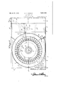
- v Figure 1 is a vgeneral top plan view of the 3o" device of the invention showing certain por'- tionsthereo in dotted lines.
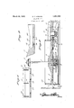
- Figure 2 is a vertical longitudinal section-al view taken approximately on the line2--2 ⁇ of Figure 1.
- Figure v3 1 s a partial sectional View taken approximately on the line 3-3 of Figurel.
- Figure 4 is a transverse sectional view taken approximately on the line of Figure 1.
- a Figures 5 and 16 aresectional views taken approximately .on the lines 5-5 and 6-6 of Figure 1.
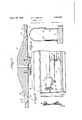
- i i v Figure 7 is an enlarged cross sectional view through the roulette wheel.
- a Figure 8 is a sectionalview taken approximatelyon the line 8--8V of Figure 7
- Figure 9 is a sectional view taken approxi'- mately at right anglesto Figure v8.
- the numeral refers generally to a casing com- 59 posed of the side walls ⁇ 6, the circular annular 1931. 'serial N9. 546,634.
- top member y7 provided with the inwardly slanting surtac'e' 8, the V,platform 9, "and the ramp 10 leading from the platform 9 tothe golf :course Aor fair way.
- rjlhe wheel 15f is centrally apertured so as to clear the sides of the column 11 about whichit rotates, being Supported u by a block -16V which, in turn, rjestsupon a 05 bearing block 17 which forms a racew'aywith the support 13 for' the ball bearing 15.
- Av large pulley 18 is secured to theunder'vside of the bearing block 117.'4 .
- a suitable IIIIV Y 19 is secured on a hinged bracket which 70 bracket is adapted to be adjusted in "a horif zontal plane for Aadjusting a belt '2;1 ⁇ V1connected with a lpulley 22 ⁇ on ashaft 23, which shaft hasV a Areducing pulley 24 whi'ch'isconnected by a bei-t 25 t the large pulley 18,@ drive 'f5 the roulette wheel 15 "at "a suitable Speed..
- Surrounding the annular member 7' isa wall 26 to properly confine va ,ball run upon'the roulette wheelv and the slanting surface 8.
- a wall 27 on eachfside ofthepl'ati 8 form) and the ramp 1Q serves tojc'omfinfe ⁇ a" ball propelled toward the hole 2,8 in the ⁇ :plat-v form, upon ⁇ the platform 9. i It should be. stated that the wall 26fis4not completelyleir# cular, but it is broken at 29, and the end30 95 is outwardly deflected tojforin a gateover which a U-shaped member 31 forms jan such..
- the lever 36 consists of a n'lainy Vportini?v which has one end 38 under'lthe circumfer j y entialiline of the cups 16 ofthe-roulette wheel, 10
- a mercury contact structure 43 is supported on the upper part'of the main portion 37 of the lever 36 and suitable-conduits 4 4 lead from the mercury circuit closer to the motor 19.
- the cups ofthe roulette wheel are vformed by adjacent pairs of metalli'cseparators 45. having the projectionf46, and reference to Figures 5, 7, 8 and 9 will give a clear idea of the structure of the cups which have flared holes 47 in the bottoms for permitting a ball 48 to partly ldrop therethrough so as to contact the end 38 lof the lever 36 for a purpose to be described.
- kAn annularchannel 49 runs around the wheel within the outer periphery thereof and forms with the separators and ⁇ A the holes 47 the cups of the wheel, 'which may be numbered or designated-many desired manner. It will be observed that the separators 45 have their lower edges slightly above the bottom 50 of the channel 49.
- a golf ball or thelike is propelled up the ramp V10 on to the platform 9 and into the holey 28.
- the ball travels'through the hole 28 into the chute 34 it is positioned during its tra-velto strike and depress the plate 35 on the lever 36 and cause the overbalancing lof the lever sorthat the mercury in thev circuit closer 43 flows to the end vof the mercury tube corresponding to the position of the plate 35 on the lever 36, and closes the circuit through the motor 19 which thereupon rotates the roulette wheel 15.
- the ball 48 continuesA through the chute 33 after striking the plate 35 and is to be recovered in the receptacle 32. The next move is to place the ball 28 upon the platform 9 and propel the same through the gate under the arch 31.
- a golf apparatus of the type described comprising a casing including a ramp, a platform, aplaying hole in the platform, and a walled annular area having an inwardly slanting surface, a roulette wheel within the annular area, pockets in the roulette wheelV for. receiving a ball propelled upon the said area and onto said wheel so as to permit the ⁇ ball to come to rest projecting partially below the under surface 0f the wheel, a motor, ⁇ and an operative connection between the motor and the'v roulette wheelv for rotating the wheel, and switch means for automatically starting rthe motor when, a ball is played into said hole,.and means for stopping the motor and permitting said wheel to lose momentum i and stop when a ballhas come to rest in one of said pockets.
- a golf apparatus of the type described comprising a casing including-.a ramp, a platform, a playing hole inthe platform, and a walled lannular area having' an inwardly slanting surface, a roulette ywheel within the annular area, pocketsin the roulettey wheel for receiving aV ball propelled upon thesaid area and onto said wheel so vas to permity the ball to come to rest projecting partiallybelow the under surfaceof the wheel, a motor,
- switch means for automatically starting the'motor when a ball is played into said hole, and means for stopping the motor and permitting said wheel to lose momentum and stop when'a ball has come to rest in one los y of said pockets, said switch means comprisiw ing a lever mounted rockably under said hole and said pockets, whereby'to-be operated by j a ball in said hole or pockets, and a gravity operated circuit closing means on the lever for closing and opening a circuit to the motor.
- a golf apparatus'ofthe type described comprising av casing including ay ramp, a platform, a playing hole in they platform, and awalled annular areahaving an inwardly slant- ⁇ ing surface, a roulette wheel within the annular area, pockets in the roulette wheel within the annular area, pockets in the roulette wheel for receiving a ball propelled upon the said area and onto said wheel soas .to permit the ball to come to rest projecting partially below the under surface of the wheel, a motor, and an operative connection between the motor and the roulette Wheel for rotating the wheel, and switch means for automatically starting the motor when a ball is played into said hole, and means for stopping the motor and permitting said wheel to lose momentum and stop when a ball has come to rest in one of said pockets, said switch means comprising a lever mounted rockably under said hole and said pockets, whereby to be operated by a ball in said hole or pockets, and a gravity opera-ted circuit closing means on the lever for closing and opening a circuit to the motor, and a stationary lamp support on the
Landscapes
- Engineering & Computer Science (AREA)
- Multimedia (AREA)
- Toys (AREA)
Description
Inv enlor W. T. HERRICK ROULETTE GOLF v Mauth Z9, QSZ
Filed June '24, 1931 4 Sheets-Sheet flliomey March 29, 1932. w. T. HERRICK ROULETTE GOLF 4 Sheets-Sheet 2 Filed June 24, 1931 March 29, l1932. w.` T. HERRICK ROULETTE GOLF Filed June 24, 1951 4 Sheets-Sheet 3 Invenlor Pfff/25%) 756/72 by@ f1 Homey March 29, 1932s w. T. HERRICK ROULETTE GOLF 4 Sheets-Sheet 4 Filedl June 24, 195.1
,/1 Homey Patented Mar. 29, 1932 N uNlTED'sTATEs WILLIAM T. HERRICK, 0F TULSA,4 OKLAHOMA RQULETTE ,GOLF
n Application filed June 24,
This invention relates to a new and novel game and apparatus for playing the lsame, which is in the nature of a fixture for miniature golf courses or similar apparatus and which is adapted to be used as `an individual unit for either indoor or outdoor use.
It an important object of my invention to provide a roulette wheel device incorporated in a supporting structure, the roulette wheel being 'adaptedfto be set into motion upon 'certa-in movements of a ball, such `as a golf ball, which has been propelled into a cup or hole. f V f It is another objectof this invention to provide a new and novel apparatus of the type described, which isentirely automaticin its operation, which is simple and )easy and inexpensive to construct and install, and which .has the other features of noveltyY and advantage which' will be better understood fas the descriptionproceeds below.
These and other objects or" the invention, its nature, and its composition and arrange'- ment and `combination of parts will bedreadi- 2'5" ly understood by any one acquainted `with the art to which this invention relates upon consulting the following descriptions of the drawings, in which: v Figure 1 is a vgeneral top plan view of the 3o" device of the invention showing certain por'- tionsthereo in dotted lines. A
Figure 2 is a vertical longitudinal section-al view taken approximately on the line2--2 `of Figure 1.
Figure v3 1s a partial sectional View taken approximately on the line 3-3 of Figurel.
Figure 4 is a transverse sectional view taken approximately on the line of Figure 1. A Figures 5 and 16 aresectional views taken approximately .on the lines 5-5 and 6-6 of Figure 1. i i v Figure 7 is an enlarged cross sectional view through the roulette wheel. A Figure 8 is a sectionalview taken approximatelyon the line 8--8V of Figure 7 Figure 9 is a sectional view taken approxi'- mately at right anglesto Figure v8. L e
Referring in detail to vthe drawings, the numeral refers generally to a casing com- 59 posed of the side walls `6, the circular annular 1931. 'serial N9. 546,634.
top member y7 provided with the inwardly slanting surtac'e' 8, the V,platform 9, "and the ramp 10 leading from the platform 9 tothe golf :course Aor fair way. A 'colu`mn11fis supportedin the middle of the ffloo'r l2 by` the 55 bearing support 13,V and the "column 1.1 basenl its upper end la lamp structure 14` forillumihating the roulette wheel, generally desifgnaft ed V15, which is `of conventional structure e`xcept for the pockets-generally referred to by the numeral 16 which will' be subsequently described. rjlhe wheel 15fis centrally apertured so as to clear the sides of the column 11 about whichit rotates, being Supported u by a block -16V which, in turn, rjestsupon a 05 bearing block 17 which forms a racew'aywith the support 13 for' the ball bearing 15. Av large pulley 18 is secured to theunder'vside of the bearing block 117.'4 .A suitable IIIIV Y 19 is secured on a hinged bracket which 70 bracket is adapted to be adjusted in "a horif zontal plane for Aadjusting a belt '2;1`V1connected with a lpulley 22 `on ashaft 23, which shaft hasV a Areducing pulley 24 whi'ch'isconnected by a bei-t 25 t the large pulley 18,@ drive 'f5 the roulette wheel 15 "at "a suitable Speed.. Surrounding the annular member 7' isa wall 26 to properly confine va ,ball run upon'the roulette wheelv and the slanting surface 8. Y Similarly a wall 27 on eachfside ofthepl'ati 8 form) and the ramp 1Q serves tojc'omfinfe `a" ball propelled toward the hole 2,8 in the` :plat-v form, upon `the platform 9. i It should be. stated that the wall 26fis4not completelyleir# cular, but it is broken at 29, and the end30 95 is outwardly deflected tojforin a gateover which a U-shaped member 31 forms jan auch.. At one vside of the rampat 32 is provi'd'eda cup or receptacle .to which is connected' tilln-V way or chute 33 open 'at its upper end ad- 9 jacent to the hole 28.v 'Ihe hole 28 is provided with an elbow vchute whose ,loivelfj` end opens u on a plate 35 on one 'end of a lever genera ly designated 36. The openuplf. y
" per end `of the chute 33 is adapted to receive 95 a ball projected into thehole 28, asth'e'ball leaves the plate 35'aft'er strikingthe same.`
The lever 36 consists of a n'lainy Vportini?v which has one end 38 under'lthe circumfer j y entialiline of the cups 16 ofthe-roulette wheel, 10
and it is rockably supported by a standard 39 on a base 40 with spring means generally designated 41 for maintaining it normally in a position in which the S-shaped portion 42 carrying the plate is depressed. A mercury contact structure 43 is supported on the upper part'of the main portion 37 of the lever 36 and suitable-conduits 4 4 lead from the mercury circuit closer to the motor 19.
The cups ofthe roulette wheel are vformed by adjacent pairs of metalli'cseparators 45. having the projectionf46, and reference to Figures 5, 7, 8 and 9 will give a clear idea of the structure of the cups which have flared holes 47 in the bottoms for permitting a ball 48 to partly ldrop therethrough so as to contact the end 38 lof the lever 36 for a purpose to be described. kAn annularchannel 49 runs around the wheel within the outer periphery thereof and forms with the separators and `A the holes 47 the cups of the wheel, 'which may be numbered or designated-many desired manner. It will be observed that the separators 45 have their lower edges slightly above the bottom 50 of the channel 49.
The operation of the device is 'as follows: A golf ball or thelike is propelled up the ramp V10 on to the platform 9 and into the holey 28. As the ball travels'through the hole 28 into the chute 34 it is positioned during its tra-velto strike and depress the plate 35 on the lever 36 and cause the overbalancing lof the lever sorthat the mercury in thev circuit closer 43 flows to the end vof the mercury tube corresponding to the position of the plate 35 on the lever 36, and closes the circuit through the motor 19 which thereupon rotates the roulette wheel 15. The ball 48 continuesA through the chute 33 after striking the plate 35 and is to be recovered in the receptacle 32. The next move is to place the ball 28 upon the platform 9 and propel the same through the gate under the arch 31. As the ball travels through the gate, depending upon its speed and momentum it will travel around the slanting surfaceS until the moi mentum dies downand the slanting surface 8 conveys the ball upon the roulette wheel 15. Finally Vthe ball 28 will come to rest in one of the pockets or cups 16, and the roulette wheel carries the ball around until the ball protruding vthrough the opening 47 in which it' restswill strike the end 38 of the lever 36 and cause the depression thereof, so as toy permit the mercury inthe circuit breaker to flow tothe end of the tube corresponding to i the end of the lever ,38, whereupon the circuit through the motor is broken, and the rotation of the roulette wheelfcomes to an end. During the swinging of the lever 36 the spring detent 41 snaps from one side to the other of theV spring projected element 41a whichk worksjto maintain the lever 36 depressed' at either end according to its actuation. y l Itis obvious the device of the invention blocks 52 are deemed a valuable feature of the construction, as theyv properly support the roulette wheel and the casing 5.
It is to be definitely understood that I do not desire tolimit Athe application of this Y invention to the particular modification set out herein to illustrate the principles thereof, and any change or changes may be made consistent with the spirit and scope Yof Athe' invention. y
What 1s claimed 1s:
1. A golf apparatus of the type described comprising a casing including a ramp, a platform, aplaying hole in the platform, and a walled annular area having an inwardly slanting surface, a roulette wheel within the annular area, pockets in the roulette wheelV for. receiving a ball propelled upon the said area and onto said wheel so as to permit the` ball to come to rest projecting partially below the under surface 0f the wheel, a motor,` and an operative connection between the motor and the'v roulette wheelv for rotating the wheel, and switch means for automatically starting rthe motor when, a ball is played into said hole,.and means for stopping the motor and permitting said wheel to lose momentum i and stop when a ballhas come to rest in one of said pockets.
. 2. A golf apparatus of the type described comprising a casing including-.a ramp, a platform, a playing hole inthe platform, and a walled lannular area having' an inwardly slanting surface, a roulette ywheel within the annular area, pocketsin the roulettey wheel for receiving aV ball propelled upon thesaid area and onto said wheel so vas to permity the ball to come to rest projecting partiallybelow the under surfaceof the wheel, a motor,
and an operative connection between the mo-A tor and the roulette wheel for 'rotating the wheel, and switch means for automatically starting the'motor when a ball is played into said hole, and means for stopping the motor and permitting said wheel to lose momentum and stop when'a ball has come to rest in one los y of said pockets, said switch means comprisiw ing a lever mounted rockably under said hole and said pockets, whereby'to-be operated by j a ball in said hole or pockets, and a gravity operated circuit closing means on the lever for closing and opening a circuit to the motor.
3. A golf apparatus'ofthe type described comprising av casing including ay ramp, a platform, a playing hole in they platform, and awalled annular areahaving an inwardly slant-` ing surface, a roulette wheel within the annular area, pockets in the roulette wheel within the annular area, pockets in the roulette wheel for receiving a ball propelled upon the said area and onto said wheel soas .to permit the ball to come to rest projecting partially below the under surface of the wheel, a motor, and an operative connection between the motor and the roulette Wheel for rotating the wheel, and switch means for automatically starting the motor when a ball is played into said hole, and means for stopping the motor and permitting said wheel to lose momentum and stop when a ball has come to rest in one of said pockets, said switch means comprising a lever mounted rockably under said hole and said pockets, whereby to be operated by a ball in said hole or pockets, and a gravity opera-ted circuit closing means on the lever for closing and opening a circuit to the motor, and a stationary lamp support on the casing extended through said roulette wheel for illuminating the wheel, platform and ramp.
In testimony whereof I affix my signature.
WILLIAM 'I'. HERRICK.
Priority Applications (1)
| Application Number | Priority Date | Filing Date | Title |
|---|---|---|---|
| US546634A US1851628A (en) | 1931-06-24 | 1931-06-24 | Roulette golf |
Applications Claiming Priority (1)
| Application Number | Priority Date | Filing Date | Title |
|---|---|---|---|
| US546634A US1851628A (en) | 1931-06-24 | 1931-06-24 | Roulette golf |
Publications (1)
| Publication Number | Publication Date |
|---|---|
| US1851628A true US1851628A (en) | 1932-03-29 |
Family
ID=24181311
Family Applications (1)
| Application Number | Title | Priority Date | Filing Date |
|---|---|---|---|
| US546634A Expired - Lifetime US1851628A (en) | 1931-06-24 | 1931-06-24 | Roulette golf |
Country Status (1)
| Country | Link |
|---|---|
| US (1) | US1851628A (en) |
Cited By (2)
| Publication number | Priority date | Publication date | Assignee | Title |
|---|---|---|---|---|
| US2660434A (en) * | 1951-07-16 | 1953-11-24 | Gen Patent Corp | Pocketed ball game apparatus |
| US20040150992A1 (en) * | 2003-01-16 | 2004-08-05 | Elektoncek, Podjetje Za Razvoj | Structure for illuminating a roulette wheel |
-
1931
- 1931-06-24 US US546634A patent/US1851628A/en not_active Expired - Lifetime
Cited By (3)
| Publication number | Priority date | Publication date | Assignee | Title |
|---|---|---|---|---|
| US2660434A (en) * | 1951-07-16 | 1953-11-24 | Gen Patent Corp | Pocketed ball game apparatus |
| US20040150992A1 (en) * | 2003-01-16 | 2004-08-05 | Elektoncek, Podjetje Za Razvoj | Structure for illuminating a roulette wheel |
| US7118247B2 (en) * | 2003-01-16 | 2006-10-10 | Elektroncek D.O.O. | Structure for illuminating a roulette wheel |
Similar Documents
| Publication | Publication Date | Title |
|---|---|---|
| CN102711934A (en) | A toy spinning top | |
| US1851628A (en) | Roulette golf | |
| US3208751A (en) | Game apparatus with ball dropping means and rotating target | |
| US861841A (en) | Base-ball-game apparatus. | |
| US3643955A (en) | Skill-type game | |
| US1449565A (en) | Game | |
| US2230064A (en) | Ball rolling game | |
| CN107569847B (en) | Toy for rolling glass ball of children toy | |
| US2199327A (en) | Game device | |
| US503022A (en) | Daniel whitburn | |
| US1982633A (en) | Game | |
| US1103865A (en) | Game apparatus. | |
| GB211283A (en) | Apparatus for use in playing games of skill | |
| US3468535A (en) | Scoring device | |
| US1512985A (en) | Amusement apparatus | |
| US1524378A (en) | Game apparatus | |
| US1713247A (en) | Mechanical ball game | |
| US1337773A (en) | Parlor-baseball game | |
| JP3735852B2 (en) | Gift acquisition game machine | |
| CN223324011U (en) | A gaming device with a scoring function | |
| US855455A (en) | Game. | |
| US1568852A (en) | Game apparatus | |
| CN108970127A (en) | A kind of town squares children pitching amusement equipment | |
| US2044177A (en) | Ball table | |
| CN203777657U (en) | Labyrinth two-hand coordination machine with multiple rotary plates |