US1851625A - Heel seat cutting mechanism - Google Patents
Heel seat cutting mechanism Download PDFInfo
- Publication number
- US1851625A US1851625A US497275A US49727530A US1851625A US 1851625 A US1851625 A US 1851625A US 497275 A US497275 A US 497275A US 49727530 A US49727530 A US 49727530A US 1851625 A US1851625 A US 1851625A
- Authority
- US
- United States
- Prior art keywords
- plate
- die plate
- die
- heel
- shoe
- Prior art date
- Legal status (The legal status is an assumption and is not a legal conclusion. Google has not performed a legal analysis and makes no representation as to the accuracy of the status listed.)
- Expired - Lifetime
Links
- 238000010276 construction Methods 0.000 description 3
- 230000000994 depressogenic effect Effects 0.000 description 2
- 238000000926 separation method Methods 0.000 description 2
- 101100340610 Mus musculus Igdcc3 gene Proteins 0.000 description 1
- 230000000295 complement effect Effects 0.000 description 1
- 230000033001 locomotion Effects 0.000 description 1
- 238000007493 shaping process Methods 0.000 description 1
Images

Classifications
-
- A—HUMAN NECESSITIES
- A43—FOOTWEAR
- A43D—MACHINES, TOOLS, EQUIPMENT OR METHODS FOR MANUFACTURING OR REPAIRING FOOTWEAR
- A43D8/00—Machines for cutting, ornamenting, marking or otherwise working up shoe part blanks
- A43D8/32—Working on edges or margins
- A43D8/34—Working on edges or margins by skiving
-
- A—HUMAN NECESSITIES
- A43—FOOTWEAR
- A43D—MACHINES, TOOLS, EQUIPMENT OR METHODS FOR MANUFACTURING OR REPAIRING FOOTWEAR
- A43D8/00—Machines for cutting, ornamenting, marking or otherwise working up shoe part blanks
- A43D8/46—Splitting
- A43D8/48—Splitting combined with skiving
Definitions
- This invention is a novel improvement in, machines for cutting heel seats in soles of shoes, either before or after the soles' have been attached to the shoe.
- the invention is an improvement in the type of machines shown in Keith et a l. Patent No. 104,599 and Allen Patent No. 1,027,638. Its principal object is to provide a simple mechanism whereby segments may be simultaneously cut from opposite sides of the heel portion of a sole preferably. after the sole isattached to the shoe, so that the heel when seated thereon will maka close fit with thecounter portion of the shoe upper.
- a further. object is to provide a heel seatin g mechanism which can be readily attached to 'or mounted for operation on an ordinary die press or the like so that the attachment can be easily operated by power if desired.
- the attachment essentially comprises a movable punch plate cooperating with a fixed die plate to cut segments from opposite sides of the heel portion of a sole; the die plate being preferably tapered on its under side to a thin edge at its front side so that the unattached heel portion of a shoe sole can be easily slipped thereover when positioning a shoe thereunder.
- the punch plate is-normallv spaced from the, die plate by springs.
- die plate can be depressed b manually operated means: but is preferably actuated by a reciprocating plunger which may be automatically stopped at the end of each reciprocation by ordinary stop means to enable shoes to be positioned under the die plate foroperation thereon. and removed after the operation and replaced by another to be operated upon.
- I preferably arrange beneath the die plate a gage or'stop against whichthe shoe is positioned preparatory to being operated upon.
- a shoe with a sole attached is positioned against the gage and beneath the die plate.
- the thin edge i of the die plate enters between the unattached end of the sole and the heel portion of the shoe as the latter is positioned against the gage.
- the punch plate is forced down and puches segments from opposite sides of the heel portion of the sole.
- the present invention has particular reference to the construction of the said dic plate, the cooperating punch plate, and the means for mounting them in operative relation; i
- the said devices can be readily attached to various forms of punch presses, and in the machine shown the devices are mounted on an ordinary type of punch pressso that they maybe actuated by the mechanism of said press.
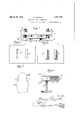
- Fig. 2 is a side view of Fig. 1.
- Fig. 3 is an enlarged'detail vertical sectional View.
- Fig. 4 is an enlarged front view of the punch and die plate assembly detached. 7
- Fig. 5 is a top plan view of the ,die plate detachedj
- I Fig. 6 is a bottom plan view of the punch plate detached. I i
- Fig. is a detail view ofthe heel portion ofasole'
- V e 5H1 Fig. .8 is a detail sectional view of the gage supporting devices.
- V I The essential features of my heel'seating attachment are a the plate 1; a related punch plate 2, mounted above the die plate but ac curately positioned and guided in its move ment relative tothe die plate by meansof stud bolts 8 fixed to the die plate and pro jecting through guide openings in the punch plate; which is normally spaced from'the die plate by springs 4 strung on thestu'dbolts 3 between the die and punch plate the separation ofthefldie plate from th'ep-unch plate is limited by suitable adjustable stops.
- the die plate 1 is provided with two spaced die openings 1a with which cooperate correspondingly located complementary punches 2a on the lower face of the punch plate.
- the punches and die openings operate on the heel portion of a shoe sole as hereinafter eX plained.”
- the forward edge of the die plate 1 inter v mediate its ends is preferably beveled on its upper side, being thinnest at its front edge as shownin Figs: 3 and 4, and tapering rear wardly and downwardly to its rear and this thin edge of the die plate enters between the unattached portion I-I ofthe sole and the body L of the shoe when the heel portion of the shoe is being positioned belowv the die plate and against the gage 5 as shown in Fig. 3. greatly facilitates the operation between the die and punc plates when the latter in raised position, and then the punch plate forced down and its punches cooperatewitli the die openings to simultaneously cut segmentsa from opposite sidesof the heel portion of thesole.
- Such heel portion after being thus shaped is adapted to enter a corresponding recess in the upper portion ofthe heel which is subsequently fastened to the shoe.
- the punch plate may be forced down or toward the die plate so asto cause the 'punches to operate with the dies by.
- the said attachment may be mounted upon 5 any suitable operating press.
- the die plate being supported on upright members 6 bolted to the frame of the press below the plunger thereof; said die plate preferably has fiangesle atits ends which are engaged by clamps 6a attached to the upper ends of membersti so as to properlyposition the die plate thereon and hold it rigidly in position beneath the reciprocatory plunger P of the. press.
- the plunger P can be reciprocated byany suitable means ascommonly used in such presses, from or by the shaft T on which is rotatably mounted a wheel W that can be locked on ordisengaged from the shaft by 'means ofclutch member
- ber can be throwninto and out of operation by a stop D which may be moved into operative position by means of trip rod E connected to a tre'adle, not shown.
- Suchopers' ating and controlling devices for plunger P are common in the art (see for example Ronan Patent 956,422 or Allen Patent 1,027,- 638) and form no partof the present invention and further description thereof is needess. I a
- a gage 5 As commonly used in heel seating machines against which the heel portion of the last L, carrying the shoe to be operated upon, is positioned prior to operating the punch plate.
- This gage may be of any suitable construction, and as shown has a shank 5a slidably fitted in a holder 8 fastened to a cross plate 7 I) attached to the members 6 below the die plate 1."
- the shank has a reduced portion 56 extending through an open ingin the rear end ofthe guide 8, and an expansionspring 58 is interposed between the shank 5a and the end of the guide 8.
- gage 5 when in use may be adjusted to suit the size of shoes to be operated upon, and then rigidly fastened by any suitable means, as a hand screw 86 tapped through a threaded opening in the side of the, guide 8 I and engaging the shank 5a, see ,Fig. 8 I
- the device may also be used in the form shown for shaping the heel portion of the shoesattaehed to the upper of the shoe but before the heel portions are themselves secured.
- a last with a shoe thereon having its sole partly attachedbut'its heel portion loose is positioned beneath, the die j plate with the loose heel portion H of the sole overlying the dieplate 1 and between the latter. and the punch plate 2 as shownin Fig. 3.
- the plunger is operated to depress the punch plate to cut segments a from opposite sides of the heel portion of the sole.
- The, last is then removed and the heel portion of the sole afterwards fastened to the insole, and a heel attached thereto.
- a heel seating machine the combination with a press having a plunger of heel seating devices mounted on the press in posit-ion to be operated by the plunger; said de vices including a die plate tapered on its 'un-' derside and thinnest at its upper forward edge to facilitate positioning of the u'nattached heelportion of the sole of a shoe there on; a cooperating punch'pl'ate, andm'ean-s for normally separating the plates.
- a press having a reciprocable plunger; supporting members on the press frame below the plunger, a die plate mounted upon saidmembers andtapered on its underside and thinnest at its'upper forward edge, the thin edge of the die plate being adapted to enter between the heel portion of the sole and the shoe, as the latter is positioned beneath the die plate, a punch plate operating with the die plate, and means for normally separating the plates.
- a press having a reciprocable plunger; supporting members on the press frame below the plunger, a die plate mounted upon said members tapered on its underside and thinnest at its upper forward edge, the thin edge of the die being adapted to enter between the heel portion of the sole and the shoe, a cooperating punch plate having punches corresponding with a die, guides for the punch plate, springs for normally separating the plates, and a gage for positioning a shoe under the die plate.
- Heel seating devices comprising a die plate having two die openings therein separated less than the width of the heel portion of the shoe sole, a cooperating punch plate having two punches opposite to and corresponding with the die openings in the die plate, means for normally separating the plates, and means for relatively moving the plates'to cause the dies and punches to cut segments from opposite sides of the heel portion of a sole inserted therebetween.
- Heel seating devices comprising a die plate having two die openings separated less than the width of the heel portion of a sole, a cooperating punch plate having two punches opposite to and corresponding with the die openings in the die plate, guides attached to one plate and engaging the other plate, springs interposed between the plates for normally separating them, a gage beneath the die plate for positioning a shoe thereunder with the heel portion of the sole overlying the die plate, and means adapted to depress the punch plate to cause the dies to cut segments from opposite sides of the heel portion of a sole inserted therebetween.
- heel seating devices including a die plate mounted upon the press frame having spaced openings below the plunger, said die plate being tapered on its underside and thinnest at its upper forward edge, the thin edge of the die plate being adapted to enter between the heel portion of the sole and the shoe as the latter is positioned beneath the die plate, a cooperating punch plate havin spaced punches corresponding with the openings in the die plate,studs attached to one plate and engaging guide openings in the other plate, and spring means for normally separating the plates.
- a press having a reciprocable plunger; supporting members mounted on the press frame below the plunger, a die plate mounted upon said members said plate having spaced openings and tapered on its underside and thinnest at its upper, forward edge, the thin edge of the die plate being adapted to enter between the heel portion of the sole and the shoe, a cooperating punch plate having spaced punches corresponding with the die openings in the die plate, guide studs attached to one plate and engaging guide openings in the other plate, springs strung on the bolts between the plates for normally separating the plates, means for limiting the separation of the plates, and a gage beneath the die plate for positioning a shoe thereunder.
Landscapes
- Footwear And Its Accessory, Manufacturing Method And Apparatuses (AREA)
Description
March 29, 1932. H. GlNGELL 1,851,625
HEEL SEAT CUTTING MECHANISM Filed Nov. 21, 1930 2 sheets-Sheet 1 j W W K Filed Nov] 21, 1350 H. GINGELL 1,851,625
HEEL SEAT CUTTING MECHANISM 2 Sheets-Sheet 2 MIN WIPE 7 il? 8 5 i 1 M gwuantox Patented Mar. 29, 1932 UNITED STATES PATENT OFFICE HARRY GINGELL, OFJOHNSON CITY, NEW YORK, ASSIGNOR TO ENDICOTT JOHNSON COR- i PORATION, 0F ENDICOTT; NEW YORK, A CORPORATION OF NEW YORK I HEEL SEAT CUTTING MECHANISM 1 Application filed November2l, 1930. Serial No; 497,275.
This invention is a novel improvement in, machines for cutting heel seats in soles of shoes, either before or after the soles' have been attached to the shoe. The invention is an improvement in the type of machines shown in Keith et a l. Patent No. 104,599 and Allen Patent No. 1,027,638. Its principal object is to provide a simple mechanism whereby segments may be simultaneously cut from opposite sides of the heel portion of a sole preferably. after the sole isattached to the shoe, so that the heel when seated thereon will maka close fit with thecounter portion of the shoe upper.
A further. object is to provide a heel seatin g mechanism which can be readily attached to 'or mounted for operation on an ordinary die press or the like so that the attachment can be easily operated by power if desired.
The attachment essentially comprises a movable punch plate cooperating with a fixed die plate to cut segments from opposite sides of the heel portion of a sole; the die plate being preferably tapered on its under side to a thin edge at its front side so that the unattached heel portion of a shoe sole can be easily slipped thereover when positioning a shoe thereunder. The punch plate is-normallv spaced from the, die plate by springs. The;
die plate can be depressed b manually operated means: but is preferably actuated by a reciprocating plunger which may be automatically stopped at the end of each reciprocation by ordinary stop means to enable shoes to be positioned under the die plate foroperation thereon. and removed after the operation and replaced by another to be operated upon.
I preferably arrange beneath the die plate a gage or'stop against whichthe shoe is positioned preparatory to being operated upon.
In operation a shoe with a sole attached is positioned against the gage and beneath the die plate. the thin edge i of the die plate enters between the unattached end of the sole and the heel portion of the shoe as the latter is positioned against the gage. such heel portion of the sole overlying the die plate and then the punch plate is forced down and puches segments from opposite sides of the heel portion of the sole. V
The present invention has particular reference to the construction of the said dic plate, the cooperating punch plate, and the means for mounting them in operative relation; i
The said devices can be readily attached to various forms of punch presses, and in the machine shown the devices are mounted on an ordinary type of punch pressso that they maybe actuated by the mechanism of said press.
I will explain the invention in detail with reference to the accompanying drawings. The novel features of construction and novel combinations of parts for which protection die press with mynovel heel seating attachment applied thereto.
Fig. 2 is a side view of Fig. 1. Fig. 3 is an enlarged'detail vertical sectional View. Fig. 4 is an enlarged front view of the punch and die plate assembly detached. 7
Fig. 5 is a top plan view of the ,die plate detachedj I Fig. 6 is a bottom plan view of the punch plate detached. I i
Fig. is a detail view ofthe heel portion ofasole' V e 5H1 Fig. .8 is a detail sectional view of the gage supporting devices. V I The essential features of my heel'seating attachment are a the plate 1; a related punch plate 2, mounted above the die plate but ac curately positioned and guided in its move ment relative tothe die plate by meansof stud bolts 8 fixed to the die plate and pro jecting through guide openings in the punch plate; which is normally spaced from'the die plate by springs 4 strung on thestu'dbolts 3 between the die and punch plate the separation ofthefldie plate from th'ep-unch plate is limited by suitable adjustable stops.
ends of the studs 3. i
7 The die plate 1 is provided with two spaced die openings 1a with which cooperate correspondingly located complementary punches 2a on the lower face of the punch plate. The punches and die openings operate on the heel portion of a shoe sole as hereinafter eX plained."
The forward edge of the die plate 1 inter v mediate its ends is preferably beveled on its upper side, being thinnest at its front edge as shownin Figs: 3 and 4, and tapering rear wardly and downwardly to its rear and this thin edge of the die plate enters between the unattached portion I-I ofthe sole and the body L of the shoe when the heel portion of the shoe is being positioned belowv the die plate and against the gage 5 as shown in Fig. 3. greatly facilitates the operation between the die and punc plates when the latter in raised position, and then the punch plate forced down and its punches cooperatewitli the die openings to simultaneously cut segmentsa from opposite sidesof the heel portion of thesole. Such heel portion after being thus shaped is adapted to enter a corresponding recess in the upper portion ofthe heel which is subsequently fastened to the shoe.
The punch plate. may be forced down or toward the die plate so asto cause the 'punches to operate with the dies by. any
suitably manually operable ineans but preferablypow-er'means are employed for this P 'PQ QwQW The said attachment may be mounted upon 5 any suitable operating press. As shown it isrnounted on an ordinarydie press, the die plate being supported on upright members 6 bolted to the frame of the press below the plunger thereof; said die plate preferably has fiangesle atits ends which are engaged by clamps 6a attached to the upper ends of membersti so as to properlyposition the die plate thereon and hold it rigidly in position beneath the reciprocatory plunger P of the. press. The plunger P can be reciprocated byany suitable means ascommonly used in such presses, from or by the shaft T on which is rotatably mounted a wheel W that can be locked on ordisengaged from the shaft by 'means ofclutch member The clutch 'mem-,
ber can be throwninto and out of operation bya stop D which may be moved into operative position by means of trip rod E connected to a tre'adle, not shown. Suchopers' ating and controlling devices for plunger P are common in the art (see for example Ronan Patent 956,422 or Allen Patent 1,027,- 638) and form no partof the present invention and further description thereof is needess. I a
Preferably beneath the die plate 1 is arranged a gage 5 as commonly used in heel seating machines against which the heel portion of the last L, carrying the shoe to be operated upon, is positioned prior to operating the punch plate. This gage may be of any suitable construction, and as shown has a shank 5a slidably fitted in a holder 8 fastened to a cross plate 7 I) attached to the members 6 below the die plate 1." The shank has a reduced portion 56 extending through an open ingin the rear end ofthe guide 8, and an expansionspring 58 is interposed between the shank 5a and the end of the guide 8.-
The gage 5 when in use may be adjusted to suit the size of shoes to be operated upon, and then rigidly fastened by any suitable means, as a hand screw 86 tapped through a threaded opening in the side of the, guide 8 I and engaging the shank 5a, see ,Fig. 8 I
The device may also be used in the form shown for shaping the heel portion of the shoesattaehed to the upper of the shoe but before the heel portions are themselves secured. When so used a last with a shoe thereon having its sole partly attachedbut'its heel portion loose, is positioned beneath, the die j plate with the loose heel portion H of the sole overlying the dieplate 1 and between the latter. and the punch plate 2 as shownin Fig. 3. Then the plunger is operated to depress the punch plate to cut segments a from opposite sides of the heel portion of the sole. The, last is then removed and the heel portion of the sole afterwards fastened to the insole, and a heel attached thereto. v
The operation of the device will be clearly understood from the foregoing description and the drawings. It isobvio us that the attachment can be readily placed on various types ofpunch presses, so that the die plate can be depressed by the plunger of such press when the latter is reciprocated.
I claim r I 1. In a heel seating machine, the combination with a press having a plunger of heel seating devices mounted on the press in posit-ion to be operated by the plunger; said de vices including a die plate tapered on its 'un-' derside and thinnest at its upper forward edge to facilitate positioning of the u'nattached heelportion of the sole of a shoe there on; a cooperating punch'pl'ate, andm'ean-s for normally separating the plates.
, 2'. In heel seat cutting mechanism, a press having a reciprocable plunger; supporting members on the press frame below the plunger, a die plate mounted upon saidmembers andtapered on its underside and thinnest at its'upper forward edge, the thin edge of the die plate being adapted to enter between the heel portion of the sole and the shoe, as the latter is positioned beneath the die plate, a punch plate operating with the die plate, and means for normally separating the plates.
3. In heel seat cutting mechanism, a press having a reciprocable plunger; supporting members on the press frame below the plunger, a die plate mounted upon said members tapered on its underside and thinnest at its upper forward edge, the thin edge of the die being adapted to enter between the heel portion of the sole and the shoe, a cooperating punch plate having punches corresponding with a die, guides for the punch plate, springs for normally separating the plates, and a gage for positioning a shoe under the die plate.
4. Heel seating devices comprising a die plate having two die openings therein separated less than the width of the heel portion of the shoe sole, a cooperating punch plate having two punches opposite to and corresponding with the die openings in the die plate, means for normally separating the plates, and means for relatively moving the plates'to cause the dies and punches to cut segments from opposite sides of the heel portion of a sole inserted therebetween.
5. Heel seating devices comprising a die plate having two die openings separated less than the width of the heel portion of a sole, a cooperating punch plate having two punches opposite to and corresponding with the die openings in the die plate, guides attached to one plate and engaging the other plate, springs interposed between the plates for normally separating them, a gage beneath the die plate for positioning a shoe thereunder with the heel portion of the sole overlying the die plate, and means adapted to depress the punch plate to cause the dies to cut segments from opposite sides of the heel portion of a sole inserted therebetween.
6. In a heel seating machine, the combination of a press having a reciprocable plunger; heel seating devices including a die plate mounted upon the press frame having spaced openings below the plunger, said die plate being tapered on its underside and thinnest at its upper forward edge, the thin edge of the die plate being adapted to enter between the heel portion of the sole and the shoe as the latter is positioned beneath the die plate, a cooperating punch plate havin spaced punches corresponding with the openings in the die plate,studs attached to one plate and engaging guide openings in the other plate, and spring means for normally separating the plates.
7. In a heel seat cutting machine, the combination of a press having a reciprocable plunger; supporting members mounted on the press frame below the plunger, a die plate mounted upon said members said plate having spaced openings and tapered on its underside and thinnest at its upper, forward edge, the thin edge of the die plate being adapted to enter between the heel portion of the sole and the shoe, a cooperating punch plate having spaced punches corresponding with the die openings in the die plate, guide studs attached to one plate and engaging guide openings in the other plate, springs strung on the bolts between the plates for normally separating the plates, means for limiting the separation of the plates, and a gage beneath the die plate for positioning a shoe thereunder.
HARRY GINGELL,
Priority Applications (1)
| Application Number | Priority Date | Filing Date | Title |
|---|---|---|---|
| US497275A US1851625A (en) | 1930-11-21 | 1930-11-21 | Heel seat cutting mechanism |
Applications Claiming Priority (1)
| Application Number | Priority Date | Filing Date | Title |
|---|---|---|---|
| US497275A US1851625A (en) | 1930-11-21 | 1930-11-21 | Heel seat cutting mechanism |
Publications (1)
| Publication Number | Publication Date |
|---|---|
| US1851625A true US1851625A (en) | 1932-03-29 |
Family
ID=23976174
Family Applications (1)
| Application Number | Title | Priority Date | Filing Date |
|---|---|---|---|
| US497275A Expired - Lifetime US1851625A (en) | 1930-11-21 | 1930-11-21 | Heel seat cutting mechanism |
Country Status (1)
| Country | Link |
|---|---|
| US (1) | US1851625A (en) |
-
1930
- 1930-11-21 US US497275A patent/US1851625A/en not_active Expired - Lifetime
Similar Documents
| Publication | Publication Date | Title |
|---|---|---|
| US1851625A (en) | Heel seat cutting mechanism | |
| US1959602A (en) | Perforating machine | |
| US1684934A (en) | Cutting die | |
| US1851626A (en) | Heel seat cutting machine | |
| US2357889A (en) | Fastener-inserting machine | |
| US1463229A (en) | Cutting machine | |
| US2718649A (en) | Means for feeding shoe stiffener blanks into machines for moulding the same | |
| US2299818A (en) | Machine for cutting sheet material | |
| GB380481A (en) | Improvements in or relating to machines for operating on soles | |
| US1934112A (en) | Bed for shoe ornamenting machinery | |
| US2183038A (en) | Die | |
| US1973065A (en) | Trimming machine | |
| US2113706A (en) | Gauge for cutting machines | |
| US2284882A (en) | Process of heel seat fitting | |
| US2065621A (en) | Machine for operating upon sheet materials | |
| US1706497A (en) | Machine for preparing heel seats | |
| US2140697A (en) | Ornamenting machine | |
| US2299336A (en) | Means for preparing the heel seats of insoles | |
| US2504283A (en) | Arrangement for producing thin articles | |
| US1301432A (en) | Lacing-stud-setting machine. | |
| US2263699A (en) | Machine for lasting the toe portion of uppers in the manufacture of shoes | |
| US3657754A (en) | Wiper stop for shoe lasting machine | |
| US2312330A (en) | Ornamenting machine | |
| US2315041A (en) | Perforating machine provided with clutch control mechanisms | |
| US1480602A (en) | Method for attaching molded counters to turn shoes |