US1851621A - Stapling machine - Google Patents
Stapling machine Download PDFInfo
- Publication number
- US1851621A US1851621A US398827A US39882729A US1851621A US 1851621 A US1851621 A US 1851621A US 398827 A US398827 A US 398827A US 39882729 A US39882729 A US 39882729A US 1851621 A US1851621 A US 1851621A
- Authority
- US
- United States
- Prior art keywords
- machine
- staple
- bar
- bars
- movement
- Prior art date
- Legal status (The legal status is an assumption and is not a legal conclusion. Google has not performed a legal analysis and makes no representation as to the accuracy of the status listed.)
- Expired - Lifetime
Links
Images

Classifications
-
- B—PERFORMING OPERATIONS; TRANSPORTING
- B27—WORKING OR PRESERVING WOOD OR SIMILAR MATERIAL; NAILING OR STAPLING MACHINES IN GENERAL
- B27F—DOVETAILED WORK; TENONS; SLOTTING MACHINES FOR WOOD OR SIMILAR MATERIAL; NAILING OR STAPLING MACHINES
- B27F7/00—Nailing or stapling; Nailed or stapled work
- B27F7/17—Stapling machines
- B27F7/19—Stapling machines with provision for bending the ends of the staples on to the work
- B27F7/21—Stapling machines with provision for bending the ends of the staples on to the work with means for forming the staples in the machine
Definitions
- FIG.r 7) is a second ratche'twheel56, and interposedbe-i tween the ratchet wheel 56 and the-ratchet? ing devices 59, so that? said disk and' said ratchet wheel 56 rotate as a unit independ entlyof the feed wheel shaft 45.
Landscapes
- Engineering & Computer Science (AREA)
- Mechanical Engineering (AREA)
- Life Sciences & Earth Sciences (AREA)
- Forests & Forestry (AREA)
- Portable Nailing Machines And Staplers (AREA)
Description
Mll'iih 29, 1932. 5:; gg 1,3515% STAPLING MACHINE 1929 4 Shets-Sheet 1 Filed Oct. 11,
INVE/YTO/2 A 5. E0:
.Ey J
March 29, 1932. A B E 1,851,621
STAPLING MACHINE Filed Oct. 11, 1929 4 Sheets-Sheet 2 fiwmme AB. 505
Arrow/v51 A. B. ED'E STAPLING MACHINE March 29, 1 932.
Filed Oct.
4 Sheets-Sheet 4 Arne/p y Patented Mar. 29, 1932 a ALBERT: 13. EDE, orloosnnlv, rumors I s'rArLING MA'oriINnf Application: filed October 11,1229; sfigiivessgsza Thisinvention relates to improvementsin stapling machines, and particularly to the class of stapling'machines used for forming and driving staples 1n themanufacture of' '5 veneer baskets, the predominant'object of the present application, which, briefly stated, in-
inventionbeing to produce a machineiof this type which'is an improvement onthe stapling machine disclosed in United States Lets ters Patent No. 1,411,007, granted on March.
28, 1922, to George A. Ede. r
The stapling machine disclosed in the patwhich received the folded material from which a basket was to be produced, and 1n the operation of this machine; the basket form was rotated by hand to-present the various faces thereof to the stapling driving mechanism of the machine so the material on the basket form might be stapled. 'It hasbeen found that the manual-rotation of the basket form materially reduced the speed of operation of the machine, and I have therefore devised the improved machine disclosed in the eludes nieans whereby the basket form of the machine may be automatically rotated during operation of the machine.
The'm'achine disclosed in the present application also includes means whereby. certain strips of veneer, forming parts of the baskets produced with the aid of my improved ma-,
chinefare supported while being appliedto baskets in the course of production, and in ad-.' dition to this my machine is provided wlth improved means for interrupting the feeding of:
the material from which'the staples are formed at predetermined times during the stapling of the baskets.
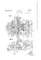
. Fig. 1 is a plan view of my improved sta-,
pling machine. I 1
Fig.2 is a longitudinal section online 2-2-'of Fig. 1. Fig. 3 is a horizontal sectional view through the machine illustratedin Figs. 1 and 2.; r Fig. 4 is aside elevation of my improved stapling machine. V
Fig. 5. is a cross-section taken on line 5+5 of Fig. 2f. J Fig. 6 isa fragmentary enlarged view illustrating -the mechanism for temporarily in the post 17 has 'a pinion 18fixed'theret0'(Fi-g."
which the staples are formed.
terrupting the feed of the 'material from I Fig. i mechanism i'lliistrated'in Fig. 61' r g Fig. -8 is a fragmentary detail illustrating 'e a part of the mechanism for automatically im-' parting rotary motionto the basket form of the-machine. r
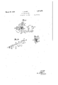
Fig.9 is ai1' enlarged section showing part :of the mechanism for'forming and driving to pthe staples. ent referred to above included a basket form I Fig. 10 is a perspective 'view of one of; the 1 staple cutting and drlving devices. 1
'Fig. llisa section'on line 11 ''-11]of1iig. 10.- i Tn thedraw1ngs,wherein is shown'for-the'es I :shaft isip'rovided withaicr'ank 4 at each sidey of which is a cam member 5 provided with j cam facesG and 7 (F igs. 1 and 3). 8 designat-es arecipr'ocatmg rodhaving its rear end 7 journaled to the crank i ofthemain shaft 3 (Fig. and having its forward end re duced to ast'em 9 at the outer end of which a nut- 10 that confines an expansionspring 1 111- The stem 9 eras reciprocating rod 8 8 i is loosely disposed in an aperture formed througha leg 12- of a reciprocating carrier 18,"whichrides upon guides 14 of the table-1 of the machine frame and is confined by bars 15 (Fig. 3). The leg -12 of the carrier 13 is heldfn'ormally projected in a rearward direction bythespring 11 on'the stem 9. 1 The 1 carrier 13 includes a slidable plate 13', and said carrier is provided with a longitudinal slot 16 (Fig; 2). Y "Q '17 designates a post, the lower. end portion of which is" extended throughthe slidable plate 13" and the longitudinalslot 16 in the carrier 13. At the extreme lower, end thereof 2), and interposed betweenthe upper face .of said pinion and thelower-facewof-a slid able. plate 13 5forming apart ofrtheicarrier t 13 is a sleeve 19, which 'su'rroundsjsa d postly de at s acoi1 sp ngwv ic en sitb 1 9, J V
7 1s a vertical section throughthey I move the post toward the rear end of the machine. The post 17 supports a basket form 21 that is rotatably mounted thereon,said basket form being adapted to receive the basket to be stapled, and is operable to move each of its sides into a position faeing'the end of the post 17 and said rack being 'pr'o vided with elongated openings23 through stapling mechanism to be hereinafter. de-..
scribed 7 slidingly supported by the carrier 13 atthe lower face thereof is a rack 22 (Figs. 2, and
8), theteeth of said rack being arranged i'n mesh with teeth of the pinion 18 at the lower which fastening devices'24, by which said rack is s'ecu-redto said carrier13, pass,.where:--j
by said rack is arrangedffor sliding movement withrespectto saidcarrier. Extended 1 'upp'enend thereof;-is- -a ratchet wheel"27 provided with fo11r.-teeth,-and *28 designates a ,pawl whioh is .pivotallyisecured tothe basket form {21 atthe' point; designated by the refer- "ence character 29. 30, designates aspring assoeiated With the pawl 28, fSaid' spring serving.'to. force the outer/end of the pawl in a I direotion toward the ratchet wheel 27.
, The iratchetgwheel 32fis' provided with four x-gtefeth, and 33 designates :a trigger, pivoted at Iyengage ,said ,teeth as lthe basket =formis, rotated. 1 T he'trigger 33 has associated with V pressed plunger which is supported in a suit *Thezbasket formj-2l includes a-verticallyr disposed;sleeve 31, which surrounds -the-post a 17, and-fixed tothe sleeve atthe lowere'nd hQIiBOfi is; a ratchet ;wheel {32 (Figs-2 and '3) 34, one ,end offlwhich is adaptedto successiveita. spring 35- which serves-to force the teeth engaging. end.- of said trigger; toward the ableretaining.housing 3,7 fixed to 'a station;
ary-part of the vframe of; themachine, said. aretaininghousinghaving a, slot 38 formed therein :through which a pin 1-39, carried by the'gplunger 36, extends. 4O designates an ex pansible coil spring which isdisposed behind 32 andthetrigger .33 is to prevent accidental rotation fof theibasket form 211 in the direc tionindicated by-the arrow in Fig. 3, it being. plain-that when-thetrigger is in engagement ported. The staple wires B (Figs. 5 2, 3, and
4) are arranged preferably on reels (not shown), which may be supported by arms 42 extending upwardly from the rear por-.
tion of the'machine frame. Thereare preferably two of the reels from each .of which a Wire is conducted to one of the guide tubes 43 supported by arms 44, whithjin turn are supported by the standards 41. The wires on passing through said tubes are directed downwardly, as seenin Fig. 2.
45 designates a feed Wheel shaft journaled ing wheels 46that are located beneath the in the standardsj41 and bearing wire feeded upon rods 48 loosely positioned in vthe;
standardg'arms '41-: The feed wheeli-shaft is y rotated through the medium of a 'r'atchiet;.:-:
wheel49 fixed thereto; and a rocker arm '50 that "carries. a spring. controlled pawlg5l I for engagement: with said ratchet wheel 49; The Y rocker arm 50-is=loosely=mounted on, thefeedto the main shaft 3 of-the machine by a connectlng- I'Od.52:.fitted to; a crank disk 53 (Fig.
wheel shaft '45, (Figs; 6 a1'1d 7), and isunitedc- 1) carried-by said main shaft. {Theo-ratchet:
hence,- as rotary motion is imparted-,to-thea ratchet wheel: 49 by the pawl-51-,the shaft} 45 :is subjectedto like rotary movement.
Loosely mounted: on. the feed wheel shaft.
45 adjacent to the rocker arm- 50.(Fig.r 7) is a second ratche'twheel56, and interposedbe-i tween the ratchet wheel 56 and the-ratchet? ing devices 59, so that? said disk and' said ratchet wheel 56 rotate as a unit independ entlyof the feed wheel shaft 45. ='desig-v; I na-tes a' second springnrgedpaw-l whi-chiis; ratchet wheel 36 designates a spring carriedby therocker arm 50, said pawl 6O being adapted to "engage-the cteeth of the" ratchet wheel '56 for the purpose oflfeeding j the ratchet-wheel56 and; the d'isk 5'7 about the=feed wheel 'shaft'45; The'pawl '51 is pro- 'Vided i a P' tion'51" whi'eh overlies the' idiskrw s n y ig: 7. ancl in the operating of the wire feeding-mechanism the:-
60, with'cthe 'result'that the pawl 51 willib'e cam= faces 58 in the disk 57 will engagegsaid portion 51 as thedisk is rotated. by-the pawl;
raisedto a position where it will not engage I the teeth" of the 'ratchet'rwheel '49; Bygthis interrupted at'predetermined periods during the staple wire delivery and: feed mechanism,
a'Ira-nge-mjent feeding of the stapleii'vire is -with one ofgtheteeth of said-ratchet wheel, as-'-shown-.:in Fig."3,*such irotationxof said ,basketformisjorevented): c 7 r '4lfdesignates the standards mounted upon- -;thejframe of-the machine by which :the staple l 'wire'ydelivery and feed mechanism-as supin', w'h'ich cross-bar are seated vertical wire guide tubes 62 into which the wires 13 enter as they are fed downwardly from the'feed wheels 46. The guide tubes 62 lead to chanpointed out. A. pair of forming fingers'fl' is rigidly-secured to eachforming bar 68,
:and the ends of these forming fingers are'provided withwire cutting edges.
. '72 designates driving bars positioned alongside of the staple forming bars 68, which driving bars are provided with drive fingers 73 positioned intermediate of the forming fingers 71 between which they operate, as
shown most clearly in Figs. 9, 10, and 11. The
bars 68 and 72 are united to each other by tongue and groove connections, as illustrated in Fig-11. 74 designates staple form fingers (Figs. 2," 3,. and 9) reciprocally positioned longitudi-' nally of'the cross-bar 61 and adapted for movement across the channels 63. .These fingers are normally projected across said channels by springs 75 located at the rear'of the fingers. .The form fingers are provided with cams 76 having beveled faces 77 (Fig. 3).
78 designates retracting slides for withdrawing the form fingers againstthe action of the springs 75.. The retracting slides are posi tioned against the guides65 andeach thereof is provided with a leg 78 that enters a notch 68' in the forming bar 68.
79 designates a pair of disks which are mounted on the main shaft 3 of the machine and are preferably formed integral'with the cam members5, each of said disksbeing provided with a pair of apertures 80 (Fig.2).
Located on each of said disksadjacent to said apertures is a plate 81 which supports pins on each of which a roller 82 is supported,
said rollers being extended through the aper-' tures 80 in the disk 79. Supported by' each plate 81 is a'pair of dowels 83, which extend into recesses in the disk 7 9, and 84 designates a screw which passes through a central openingin each of the plates 81 and screwsinto the associated disk 79 cured to the disk. v
It is apparent that in the event of the rollers 82 becoming worn by continued use, the plates 81 and said rollers may be removed by theremoval of'a single screw, that indicated whereby th'e plate is se-' by the reference character 84, and that becauseof the use of the dowels 83 the plates 81 arevery securely, fastened in place on the disks 7 85 designates 'return'bolts (Figs. 1 and 2) slidably mounted in housings 86 forming parts oftlie cap plate ,67.- These bolts are located above the staple forming and driving bars, and their rear ends project from said housings 86 toward theupstanding portion.
69 of the staple forming bars 68. Each of the return bolts is backed-by an expansion spring 87 that holds the bolt normally'pro- .Jected in a rearward direction to bear against the upstandingportions 69of the staple forming bars, as seen in Fig. 2. r 88 designates dies (Figs.'2, 3, and 9) mounted on uprights89 on the carrier 13 in positionsto place said dies directly in advance of the channels 63 in the cross-bar 61,so that when the parts of the stapling mechanism are moved the formingfingers 1 and driving fin- V gers 73 will approach the dies as suggestedin e Fig. 9.
Arranged at one side of the machine as shown in Figs. 1, 3,'and 5, is a horizontally disposed plate 91 which is secured tothe frame of the machine, and 92 designates a.
plate'which isfixed to said plate 91; The
ble of slight pivotal movement'about the fase tening device 96 so as to permittheforward ends of the arms 93 and 94 to swing with the and the rear end of said plate'92 bears against a stop pin 97 supported by the plate 91. In view of this arrangement, the plate 92 is capaplate 92 in'a' direction'toward the rear end of the machine.
- '98 designates a bell-crank lever, which is pivoted at 99 to the frameof the machine (Fig. 5), said bell-crank lever having a link 100 pivoted to an upwardly extendedleg" thereof, "which link bears against the arm 94, i;
as shown in Figs. 1 and'3. Pivotally attached I to a horizontally disposed leg 101 of the bellcranklever 98 is a connector 102 (Fig. 15),v which is:attached at its lower end to a su t able foot pedal (not shown).
The operator of the machine the thereof may depress the. foot pedal to draw theconnector 102 downwardly, and this will? rock the bell-crank lever so that the linkilOO will move the arm 94 about its pivot 94 in l a manner toseparate the forward end of said Q arm 94 from the forward end of the arm,93-..-.
7 o '1O3to'themain' shaft 3. The bar 10.4; is'pro-i This -will permit the I operator to introduce. a strip which constitutes a part. of a basket 4 being made between the forward endsj-ofithe w armsi93: and 94, and when'jthe-forward end lot the :arm 94 isagain permittedto move .toward the-forward end .ofthearm '93, said strip'willgbe guided by said arms.
113fpivotally attached thereto, which connecspring 107;
pulley may "gage a portion 121 The :plate' 118 has pawl122; the outenend of which is urged 'oy toward a ratchet wheel-12 1, iMounted 'on the shaft to which the ratchet 3 vhe'selr12 1-is' fixed is a cam 125 havingga high 7 Loosely; mounted on the: inairi shaft 3 of f the 1 machine is a ,pulley drive belt (not shown) will normally operate. The pulley lO3e-has' a clutch H1O3 of ordinary construction 7 associated; therewith,
through theinstrumentality of which the sliding movement on the frame of the machine, sa d bar-being supported at one end thereofiby a bolt which passes through a slot 106=in-the bar,and said bar at its oppositeyend beinggslidably supported by the main shaft-3 of the'machine. 107 designates a coilspringwhich is attached at one of its provided with an upwardlyextended portion 112, said operating lever having a connector toris preferably connected to a suitable pedal (not shown); Theupper end of the portion I 112 of the operating lever 111 .is disposed withinya recess '114 formed in a lug 115. arrangedon the bar 104, and by depressing the operating lever, either by hand or withcthe aid-wofthepedal'associated with the connector 113'," the ibar'10 l may be moved forwardly of theimachine. againsttheaction of the coil The' clutch 103 iii 'the'housing of the clutch and when this Vfing er is positionedas shown in F ig'. 3, the clutohi103". 1s disengaged, "while" when said finger is movedtoward'the pulley 103 said clutch is engaged so as to connect the pulley vided with'a member 117 which is adapted to engage the finger 116 when the bar l04'is in-itsrearwardposition and move'said finger fromsitsen'gagediposition to its disengaged position. 1
118, designates 'a plate 3) which is 7' I pivotedat 119'to the frame of themachine;
said plate having anupwardly and outwardly extended portion 120, which is adapted to en- 2 spring r 123 portion 125'.
103 over which a be rigidly fixed to the main shaft 104 designates a bar which is 'lIlOllIlllGdfOI" includes a llfiwhich 1 exte-nds' through a slot "(not shown) formed formed on thebar 104.51 pivoted thereto 7 a detent 126 designates a feeding gp'awl which is pivoted at 12710 the-,earrier113, said feeding pawl being; arranged to engage theteethof theratchet wheel 124'androtate a: 1 said ratchetwheel assaid-pawl. moves -for-" wardly' with the carrier.;: Th'e outergend. of :3 the feeding pawl isflmaintained; in contact with the ratchet wheel=124by-aspringl28ii In the, practical use of'this "machine I the:
stock'from which the basketisto be produced is placed over 7 condition, sothatxtherim' of. thebasket will the basket form 21 in a folded-1*.
T be at the rear of the dies 88 when the formf is rotated on its post. The strip S, whichforms a part of the basket and. which isgarranged'at the edge ofthe basketg-is then arranged between the forward ends of the 'armS 93 and 9d, as suggested by. dottedlzlines'in Fig. 1,,said forward endstof said armslbeingl separated in the manner already described;
The operating lever 111*(Fig. 4) isthenade pressed todraw the bar 10etforward1y'of the,
machine, thuspermitting the clutch finger? 116'to'1nove in a direction to cause the pulley 103=to be fixedto the main shaft 3, and asrotated by a suit-ablei:
said pulley is being source of power-said main shaft3 will besub V jectedto axial rotationii n 'The first actionof'themainshaft Sistog move the rod 8 in a rearward direction. on
such movement of Saidr'odS, 'the-carrier'13 is moved rearwardly toward-the 'cross-ban'fi'l, I3 and when rearward movement "of the-rod '8 has progressed sufiiciently theirear end. of'the racka22 wlll contact with the-forward face of the pin 26 (Fig; 2') ,Whereby-said rackwill which fme'shes' with the rack 1 22, willibe ro-,
tated. --The' pinion;18 is: fixed, to the shafti be moved forwardly with relationtothecar-r 'rier 13; 'withsthe result that the pinion '18,-
17 which shaft in turn has the ratche't wheel f 27 fixed to the-upper endthereofi'rand rotation .of the "pinion as: described will cause 7 the shaft 17 andthe'ratchet wheel; 27 to be ro-r tated in an anticlockwise direction; said ratchet wheel rotating :idly under then-pawl 28 zwithoutgimparting movementto the form 21. When-the form: is returnediby the rod the forward face of the? rack 22- moves into 7 8 to its forwardpositiomas show-n inFig. 2,
contactwith the rearmost face of-the pin-26, an'deas a result of'suchcontact the rack 22 is;
'movedrearwardly with relation to. the car-c -rier13.- This movement of the vrack results: =.s
in the-pinion 18, shaft '17, and ratchet wheel- -27 being -rotatedin 'a"Clockwisedirectionf;
whereby .saidratchet wheel 2]7 will=engage the a pawl 28 inamanner't U-cause-the'form 21 to whichthe-pawl :is pivotally attached to be rotated with saidratchetwheel. 1; Atthe time clockwise movement is impartedqtothe shaft 17 as described by rotationof-the'pinion;18,
the trigger 33 is' disengaged fromthe ratchet g 7 wheel 32 to permi,t -;such movement of vsaid sa a 1,851,621 r f j l .Thematerial of which the basket is to be formed being arranged in a folded condition on the. form, 21, and the strip S beingv 'arranged at the edge of said basket material as suggested by dotted lines i lFig. 1, the operating lever 111 will be depressed as already" described to place the, machine in operation. During the first two movements ofthe basket form 21, each of which is a fourth of a revolution, one of the cam faces 58 on the'disk 57 (Figs. 6 and 7) will be in contact with the portion 515on the pawl 51,- hence said pawl will be maintained out of contact with the teeth of the ratchet wheel 49, and therefore said ratchet wheel will remain stationary. -The ratchet wheel 49 is fixed'to the feed wheel shaft to which the wire feeding wheels 46 are secured, and therefore during the period in which the ratchet wheel 49 is stationary the, wire feeding wheels will likewise be stationary, and hence no wire will be fed during these first-two movements of the basket form. j i i V :iTheform 21 has hooks 21 secured thereto, andthe free end of. the strip S' issupported by one of these hooks so that it maynot draw away from the form. During the first two movements'of the form21 the operator merely'shapes the "strip S about the form, and as the third movement is transmitted to the form the cam-face 58, which was passing beneath theportion 51 of the pawlandthusnhe'ld said pawl-out of contact with the teeth'ofthe ratchet wheel 49, moves out of contact with said portion 51 and the outer end of the pawl 5:1 is permitted to move into contact with the teeth of said ratchet wheel 49. Movement is then transmitted to the wire feeding wheels 46, and the wires B are fed downwardly into the recesses 63 in the cross-bar 6'1.
--The cam face 7 ofeach cam member 5 comes into contact with-the rear end of a forming bar 68 moving the fingers 71 of said bar into one of the channels 63 of the cross-bar 61, and
the forewardcutting edges of said fin ers act to seversections of the stapling wire which projects downwardly into said channel at the rear of the form bar 74 :Which is normally Continued movement of the forming fingers 71 results in the formation of a staple which is produced on the form bar 7 4-between the forming fingers 71, as seen in Fig; 9. As soon as the staples have been producedthe movement of the forming slide bars results in the retracting slides 7 8 engagingrthe beveled faces 77 v of the cams 76 on the form bars ,7 4. When the retracting slides 7 S-engage said cams 7 6,
the form bars=74 are retracted out of the channels 63, thereby moving them to positions entirely beyond the staples. The driver fingers 7 3 of the driving bars 72 are then-carried forward under the actionof the'cams 6, .and'said driver fingers .7 3 push the previously formed staples "forwardly from their positions; o a H V it Thestaple forming barsi68 and the driver tions between the forming fingers 71 andforce them through the basket onthe basket form 21, and, their ends are clenched'by'coming in contact with the dies 88 which werev previouslymoved forwardly to the positions shown inFig.'9. 4
A complete rotation of the main shaftwill form and drive a pairofstaplesand willrei turn the basket form 21 to its forward-posi- V tion, and because of the spring-pressed return 5 bolts 85 exerting a rearward pressure agalnst the upstanding portions 69 ofthe staple forming bars 68 (Fig. 2), said staple forming bars 68 will-be forced against the cam members 5, and'as'the extendedportions of said cam members 5 rotate awayifrom the rear ends-of said staple forming-bars,; these bars will be moved rearwardly-by the action ofsaid spring pressedbolts85. I
fTo; insure the returnxmovement offthe 5 staple 5 forming bars 68, even though the sprmgs-66 should fail to function properly I p deeaclr of thegstaple 'forminabars,
68 with a cam groovex7Q (F;igs. it it which is located adjacent: to the rear end of said staple forming bar.'2,;,The .disks -79are each provided as has been explained with a pair of projecting rollers; 82. ,Assumingnow i a that the springs 87 fail to function properly,
the disks 79 will carry theirprojectinglrollers p around and said rollers will enter -.the' ca1n slide 70. in the staple forming bars 68,} becauseiof the'inclined faces within said slides i with which saidproj ecting rollers successively contact, said staple forming bars will be positively retu rnedjto theirrearward posi-.
bars 72 are arrangedto move independently under the actuation of the cams that strike them tomove them forward,butinasmuch as only the staple forming bars are engaged by the return bolts 85. and the projecting rollers 82 to move them rearwardly after theyhavje been actuated in a. forward direction, it is necessary to provide connection between the bars for the return'of the driver bars. This connection I provide by-the application of Y pins 130 to'the forming barswhich project i into longitudinal slots in the driver'bars,
and which engage the'driver bars in said slots as seen in Fig.2 to unite said bars 68 and 72 turn stroke.
vso that theywill travel together on: re
performtheir functions without causing Ide- I structive hammer blowsin' the restoring means. However, actual :experiencefhas shown that a crooked piece ofwire, or anirn withthe fdrniing bar 68.- Q a r Y n r *Dilriiig is complete operation ofmaking a restofring means a positive restoring means,
whereby thefo'rm-lng' -and driving bars are I "properly i r ed stsple, -will' occasionall'yibe eailght in athe, m achine so "as to' retardthe =finge1s 71 and 7 and-difthi'sevent the spring pressedbolts= 85 {will not restore the staple tormin and driving ibarsw It is therefore an advantage to Combine with the yielding positively-"restored when the-springs fail to -;1o perorm their functions This positive restoring means includes the rollers 82 which 1 normally pass-idlythrough the cam grooves -70 inthe rearends of the ba rs68 without transmitting"motion-to sai(l-bars,-bu't when a restoring spr-ing 87 fails to restore its bar 68,
' therb1'1ers 82 associatedwithisaid bar will en'- 'ter the ca m groove 70andeng-a-ge its inclined "wa-ll1-"so' asetozpositively restore the oar 68.
The slot and pin connecti'onata130 in Fig; 2' will cause'ithe staple driving bar 72 to return ,ba'sktthe 'form Q-Iis moved six times; each 1 movementwbeingfone foixrthf 'a' revolution,
go'f which a re idle movements in the sense that and during these six-movements, the 'firsttivo -no 'stap'ling is done during same, the strip S i i's isectlre'd 'teitheifo'u-r walls of the basket at t-hee dge threofw One- M211 rearward move-v mane ot-the form- 21' the "pawl 126 feeds the {twelve tooth ratchet Wheel 1'24- distance equivalent to twoteeth; orone sixth of a revo- 1 stapling of a basket.
V k A The'bar 1 04'is 'mai1itain'ecl i11 itsflfor- "wardposition by the' portion 1'20 of the plate 118, this engagement taking place when the operating lever 'lll is depressed to "start the machine, and as the ratchet 11681124: is moved 1 one-sixth of- "a revolutionon eech rearward movement of the form 215 said ratchetwheel 'willmakeone complete? revolution diiii'n'gthe As the sixth rearward movementof'th' form takes place, thehigh portiomr1 257onthe cam'125 depresses the end ofthe plate 118'; whereby the 'portion l 2Qof said plated-is disengaged "from thekportion' 121 of the-bar 104, thus'p'e'rmitting the spring 107 to move said bar rearwardly of the machine to disengage the'clutch 103 and *(iluring, opr'era-tion ofthe machinethe trigger eem m -r c Tween the basket form 21 1movesforwardly 733 enga es the ratchet wheel32 in armanner to-prevent rotary movement of said form in thedirectionindicated by the arrow in Fig 3, and" during i such forward "movement the m- Y V -e-li-nedface 33 50f the'triggercontacts with the 1 "outer face off the plunger 36 whereby said "plun er is'moved inwardly into the housing 1 37 :by which it 1 is supported. 1 On' rearward mov'el'nent of; the? basket form, however, the extended corner33 of. the-trigger 33 'will 'be fngaged by the plIIn'geI-BS-Whereby the oppo- "site end off-:sai d trigger willjbe' diseng aged the ratchet'wh'ee1'*B2"and said ratchet post and arranged the""pulley-'103 from the mainisha-lt 3 of I Leer-e21 wheel will permitted to belzrotatedshntil the end of the trigger at." which the: angular face}33- is located is freed from-engagement with the p1unger, :when the ratchet/. Wheel Y engaging end ofthe trigger w-ill lagaink'en -V gage theratchet wheel 32 'to prevent same from accidental rotation inithe directionaindt eated above;
1 The: springi19' forwardly until they after the form contacts with the verase-liar 61-.
permits the dies--88 nrove lmeetithe staple-lends After the stapling. operation the: spring e19 7 permits the form "to" clear the ndleS form isarot'ated; h I v While the features of*the-presentrinvem tion aredescribed as" being particulafliy adapted for use with a machine of%=the'typ'e asfsasid disclosed in} United States "Letters -Pate'nt 1,411,007,; granted on March 28 l-922,z-r to George-A; Ede, it is to be :undersjtoodth'at the features of my invention i'are a'pplicable to other stapling machines, anette-tremado not wish to be limited; in pl'acingvmy in vention in-use, tothe'usejof. rem; ling frnachin'e of the type referred "toi ing tli inentionedabove'y wnisnnsaid means including a rackemovable "with said form toward and: from saidstaple tforming and driving mechanism;- aeposts on which said form is-mounted; a pinioniorr said inmeshwith i said =rack,
said'rackeontflcts andstop means with which for causingrelative movement between s'ai'd form and said rack. 7
-52. A stapling maehi-ne'comprising 'staiple forming and 1 driving meehanism ia S71E01!!! adapted :to receive the workto be stapled, a post I onwhi c'hlsai-d form is inounted, :means fonmoving said form toward randffrom sai'd staple: forming andl z.:.drivingi rmechanism, :means for; periodically sub-j-ecting isaid form "to designed rotary movement in one dire-c;- [tion to present different portions of the work thereon to;-the staple drivingsmechanixslin' means for locking :said I fornr' to wprevent "undesigned movement thereof; in said rdireotion, the'last mentioned means including a 'toothe'd element fixed to saidform',and a trigger are ranged to engage the teeth of, said atoethed element, and means-with which said trigger r cooperatesfor rendering saidtrigger inoperative during 3 designed rotary" movement z-bf saldform v g 3; A staplin adapted to q-eeewe the workf toi b'e' stapled,
I V machine comprisin' staple forming and driving me'chanism'pawtform we e a post on which said form is mounted, means for moving said form toward and from sald staple forming and driving mechanism, means for periodically sub ecting sald form to designed rotary movement in one direction to present different portions of the work thereon to the staple drlvlng mechanism,
means for locking said form to prevent undesigned movement thereof in said direction, the last mentioned means including a toothed element fixed to said form, and a trigger arranged to engage the teeth of said toothed element, and means including a spring pressed plunger with which said trigger 00-- tary movement to present different portions of the work thereon to the staple driving mechanism, a main shaft, a clutch for opera-' tively connecting said main shaft to a source of power, manually operated means for placing said clutch in the engaged position, and means arranged in cooperation with said form for automatically disengaging said clutch after a predetermined number of movements of said form, the last mentioned means including a movable clutch operatmg bar, a
pivoted member arranged to engage said bar and retain same in a position where the clutch is in engagement, and means movable with the form for actuating said member to release said bar. i
. 5. A stapling machine comprising staple forming and driving mechanism, a form adapted to receive the work to be stapled,
means for moving said form toward and from sa d staple forming and drivlng mechanism, means for sub ect1ng said form to rotary movement to present difierent portions of the work thereon to the staple driving mechanism, a main shaft, a clutch for operatively connecting said main shaft to a source of power, manually operated means for placing said clutch in the engaged position, and means arranged in cooperation with said form for automatically disengaging said clutch after a predetermlned number of movements of said form, the last mentioned meansinclud ing a movable clutch operating bar, a member arranged to engage said bar and retain same in a position where the clutch is in engagement, and means including a ratchet wheel engaged by a pawl movable with the form for actuating said member to release said bar.
6. A stapling machine comprising a stapleforming and driving mechanism, a form adapted to receive the work to be stapled, means for moving said form toward and from form said staple-formingand driving mechanism, means for subjectingsaidi form to rotary movement in a clockwise directionto present difierent portions of the work thereon to the staple-driving mechanism, said means includ-' ing a rack movable with said form toward and from the staple-forming and driving mechanism, a post on which said form" is mounted, a pinion on said post arranged in mesh with said rack, stop means with which said rack contacts for causing said postto' move with respect to said rack, whereby designed rotary movement 1s imparted to said post in a clockwise direction, and means for locking said post against undesigned clockwise movement.
7. A stapling machine comprising astapleforming and drivinggmechanism, a form adapted to receive the workto be stapled,
means for moving said'formrtoward'and from said staple-forming and driving-mechanism, means for subjecting said form to ro-' tary movement in a clockw se direct on to present diiferent portions of the work thereon- "to the staple-driving mechanism, said means" including a rack movable with said form tov ward and from the staple-formingand driv- I ing mechanism, a post on whichsaid form is mounted, a pinion on said post arranged in y i mesh with said rack, stop means with which said rack contacts for causing said post to move with respect to said rack, whereby designed rotary movementis imparted to said post in a clockwise direction, and means for locking saidpost against undesignedclockwise movement, the last -mentloned means including a toothed element rotatable with said c form, and a trigger arranged to engage the teeth of said toothed element.
8. A stapling machine comprising a stapleforming and driving mechanism, a form adapted to'receive the work to be stapled,
means for moving said form toward and from said staple-forming and driving mechanism, means for subjecting'said form to rotarymovement in a clockwise direction to present'difi'erent portions of the work thereon to the staple-driving mechanism, said means including a rack movable with said form toward and from the staple-forming and driving mechanism a post on which said form ismounte d, a pinion on said post arranged in mesh with said rack, stop means with which said rack contacts for causing said post to move with respect to said rack, 7
whereby designed rotary movement is imparted to said post in a clockwise direction,
and means for locking said post against un designed clockwise movement, the last-mentionedmeans including a ratchet wheel rotatable with said form, and a trigger arranged to engage the teeth of said toothed element.
In testimony that I claim the foregoing I j hereunto aflix my signature.
a ALBERT no i
Priority Applications (1)
| Application Number | Priority Date | Filing Date | Title |
|---|---|---|---|
| US398827A US1851621A (en) | 1929-10-11 | 1929-10-11 | Stapling machine |
Applications Claiming Priority (1)
| Application Number | Priority Date | Filing Date | Title |
|---|---|---|---|
| US398827A US1851621A (en) | 1929-10-11 | 1929-10-11 | Stapling machine |
Publications (1)
| Publication Number | Publication Date |
|---|---|
| US1851621A true US1851621A (en) | 1932-03-29 |
Family
ID=23576939
Family Applications (1)
| Application Number | Title | Priority Date | Filing Date |
|---|---|---|---|
| US398827A Expired - Lifetime US1851621A (en) | 1929-10-11 | 1929-10-11 | Stapling machine |
Country Status (1)
| Country | Link |
|---|---|
| US (1) | US1851621A (en) |
Cited By (1)
| Publication number | Priority date | Publication date | Assignee | Title |
|---|---|---|---|---|
| US20050042060A1 (en) * | 2003-08-20 | 2005-02-24 | Ramirez Aldana Francisco Javier | Fastener closing |
-
1929
- 1929-10-11 US US398827A patent/US1851621A/en not_active Expired - Lifetime
Cited By (2)
| Publication number | Priority date | Publication date | Assignee | Title |
|---|---|---|---|---|
| US20050042060A1 (en) * | 2003-08-20 | 2005-02-24 | Ramirez Aldana Francisco Javier | Fastener closing |
| US7111378B2 (en) * | 2003-08-20 | 2006-09-26 | Hewlett-Packard Development Company, L.P. | Fastener closing |
Similar Documents
| Publication | Publication Date | Title |
|---|---|---|
| US3279673A (en) | Stapling machine | |
| US1851621A (en) | Stapling machine | |
| US937150A (en) | Machine for attaching buttons, &c., to fabric. | |
| US1719093A (en) | Mop-making machine | |
| US1829537A (en) | Stapling machine | |
| US1499270A (en) | Tack-fastened-button-attaching machine | |
| US1192628A (en) | Rivet-setting machine. | |
| US1411007A (en) | Stapling machine | |
| US419390A (en) | Stop-motion | |
| US1313942A (en) | Feeding mechanism for button-attaching machines | |
| US1749856A (en) | Fastener-setting machine | |
| US1592796A (en) | Carton-feeding means | |
| US1171473A (en) | Machine for holding and feeding brush-backs. | |
| US973377A (en) | Tag forming and affixing machine. | |
| US1253962A (en) | Wire-bound-box-blank machine. | |
| US1463890A (en) | Stapling device | |
| US1410422A (en) | Machine for use in making box parts or boxes | |
| US1224972A (en) | Button-feeding mechanism for button-attaching machines. | |
| US1028238A (en) | Tacking mechanism. | |
| US1325718A (en) | Hents | |
| US1263046A (en) | Stapling-machine. | |
| US1207818A (en) | Tagging-machine. | |
| USRE14344E (en) | Button-setting machine | |
| US921588A (en) | Box-end-stapling machine. | |
| US1309011A (en) | Planooraph co |