US1851620A - Shank and bit punch - Google Patents
Shank and bit punch Download PDFInfo
- Publication number
- US1851620A US1851620A US360386A US36038629A US1851620A US 1851620 A US1851620 A US 1851620A US 360386 A US360386 A US 360386A US 36038629 A US36038629 A US 36038629A US 1851620 A US1851620 A US 1851620A
- Authority
- US
- United States
- Prior art keywords
- bearing
- shank
- cylinder
- cylinders
- support
- Prior art date
- Legal status (The legal status is an assumption and is not a legal conclusion. Google has not performed a legal analysis and makes no representation as to the accuracy of the status listed.)
- Expired - Lifetime
Links
- 229940000425 combination drug Drugs 0.000 description 2
- 239000002657 fibrous material Substances 0.000 description 2
- 239000012530 fluid Substances 0.000 description 2
- 208000008103 Amniotic Band Syndrome Diseases 0.000 description 1
- 101100039010 Caenorhabditis elegans dis-3 gene Proteins 0.000 description 1
- 229910000831 Steel Inorganic materials 0.000 description 1
- 239000000945 filler Substances 0.000 description 1
- 239000000314 lubricant Substances 0.000 description 1
- PSGAAPLEWMOORI-PEINSRQWSA-N medroxyprogesterone acetate Chemical compound C([C@@]12C)CC(=O)C=C1[C@@H](C)C[C@@H]1[C@@H]2CC[C@]2(C)[C@@](OC(C)=O)(C(C)=O)CC[C@H]21 PSGAAPLEWMOORI-PEINSRQWSA-N 0.000 description 1
- 238000002407 reforming Methods 0.000 description 1
- 239000011435 rock Substances 0.000 description 1
- 239000004576 sand Substances 0.000 description 1
- 239000010959 steel Substances 0.000 description 1
Images
Classifications
-
- B—PERFORMING OPERATIONS; TRANSPORTING
- B21—MECHANICAL METAL-WORKING WITHOUT ESSENTIALLY REMOVING MATERIAL; PUNCHING METAL
- B21K—MAKING FORGED OR PRESSED METAL PRODUCTS, e.g. HORSE-SHOES, RIVETS, BOLTS OR WHEELS
- B21K5/00—Making tools or tool parts, e.g. pliers
- B21K5/02—Making tools or tool parts, e.g. pliers drilling-tools or other for making or working on holes
- B21K5/06—Dressing, e.g. sharpening rock drills
Definitions
- the shank and bit punchis designated generally by A and itssupport by
- the l support B may be in the form of abracket having a flange C throughjwhich extend bolts I D whereby the support may be secured to a 30 foundation or, as" is frequently done, to a drill sharpening machine (not shown) for conveying cleansing fluid from a rock drill to the hole being drilled.
- bearing 0 holding the bearing 0 is shown for this purpose andsaid bearing is'suitably by means of bolts as a holder for bushings to conform to the shape of the drillsteel y 60 Which they are intended to receive.
- the pressure mediumflut Referringjmorefparticularly to the idravvtween is to actuatepr drive a punch pin J into-an article intendedtobe f pinned out, as for instance, a drill steel K having alongitudinal passage L therethrough secured to the support B P.
- the bearing 0 serves Q having a bore "R-
- the cylinders may bemcompressed air which may be introducedinto a-centrall'chamberXof a throttle valve Y disposed rotatably a
- the .pressurefluid. flows a fronithe chamberwX infthei 'throttle valve 1 through a-portZ,1vvhich:in one position regis V s BISWith an inlet: passage: 6 leading toithe forward end of; the *feedi'n'g cylinder S,"and" in the back head V.
- That'illustrated comprises a lever f pivoted atone end to an arm on the supportQB v pivotally "connected at 1:, i one endfto the lever. f and With its other end,
- the bearing surface lies at a higher elevation than the bearing I surface b and serves as ax-support" directly beneath the e linder G and' the bearing sur faceo lies directly beneath the-fee'ding cylin i "pinning'out operation, and also that these surfaces may" be: at all times "adequately lubri'cated” This'wall'prOlOngthe-life der for which i t forms 'asupport.
- I- fTo'this end -bearing shoesu and care dis 3 40 posea beneath the: cylinders G and SreSpec-J i; Etiilyf and to which "th eyf may ;be secured in kanyzsuitable manner-
- the shoes u and 'v are preferably of such length that the? forward lportiono-f the bearing surfaces k and 0-are :atall times covered by. the said shoes.
- any scale .which may .be' broken froin -the' work and ered by the'actiomof the punch pin willj rbe pr e odgingoil'thebearing I f 1 y Y Q cy'linder, a support for-"the cylinder'having a" plurality of bearing n fd 'g: tdiff m q atone end through whichrtheoil-may bein- '1 'troduced into.- the-reservoir.
- fibrous material 4 as for instance felt, which serves to filter the oil flowing into the recess.
- Such oil may flow from the recess '3 through .a port orportsj5iin the shoe u to lubricate 5 thecontiguous surfaces of-the-;;shoe; andthe support... 7 I m, 1
- recesses 6 are formed in the ibottom'surfa'ces of the feeding cylinder S to receive'oil from thepassage 2.
- recesses L6:m'ay also bedisposed fibrous mate-' ma]. 7 to'filter theoil which flows from the recess-es to the bearing surface; bfthrough *ports 8111 the shoes;
- a percussive cylinder and a feeding cylinder having a plurality of bearing surfacesvlying atdifferent elevations, bearing shoes for the cylinders slidable on the bearing surfaces and forming covers therefor to preventthe lodging of foreign matter on said bearing surfaces, beveled sides on the support, gibs secured to the cylinders and having bevelled surfaces to slidably engage the-bevelled sides, and shims between the gibs and thecylinders inders having bevelled surfaces to slidably engage the bevelled sides.
- ports in the cylinders for conveying 011 from the recess to the bearing surfaces, and means in the recesses to filter the oil flowing from the reservoir to the bearing surfaces.
Landscapes
- Engineering & Computer Science (AREA)
- Mechanical Engineering (AREA)
- Earth Drilling (AREA)
Description
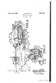
March 29, 1932. J. DITSON ET AL SHANK AND BIT PUNCH Filed May 4, 1929 a w i MN Q 1 A]. W m H 0 VG mu p 1 d u w JMN THEZE A TTORNEY Patented Mar. 29, .1932
eases amen; enumeration, Am) DUDLEY, w, HART, or 'nniivrml oononnno,
' s'sie'noies s CORPORATION OF NEWJERSEY 7 To menu-sent new COMPANY}; on ERsEYcIrxR NEW EBSEQYK A V SHA K- HW H [Application filed May 4, 192a. seria nopaeossex' I invention reIiitest p nn g t' 'jvic sand more particularly to a shank and jbit punch of the type usedfor reforming the "bores in the ends of drill steels-wand similar Working implements having passages for con-;*
" veyingcleansing fluid to thework. I
P the relatively movable surfaces of the shank {and bit punch and its support against ear.
' w an d'to assure an adequate supply of lubricant *in'suitable forrnto these surfaces.
Other objects will be in part obv'iousand in, part pointed out hereinafter.
fer to similar parts,
Figure-1 in section of a shank and bit; punch and: its
support constructed. inv accordance with the Figure 1 on the line 2+2 looking in the dis;
rection indicated byftlie arrows.
ings, the shank and bit punchis designated generally by A and itssupport by The l support B may be in the form of abracket having a flange C throughjwhich extend bolts I D whereby the support may be secured to a 30 foundation or, as" is frequently done, to a drill sharpening machine (not shown) for conveying cleansing fluid from a rock drill to the hole being drilled. i
holding the bearing 0 is shown for this purpose andsaid bearing is'suitably by means of bolts as a holder for bushings to conform to the shape of the drillsteel y 60 Which they are intended to receive.
1s a longitudinal elevation partly tively to the piston, T.. n-
, The pressure mediumflut Referringjmorefparticularly to the idravvtween: either which may consist of the usual cylinder G5 and a hammer piston H, is to actuatepr drive a punch pin J into-an article intendedtobe f pinned out, as for instance,a drill steel K having alongitudinal passage L therethrough secured to the support B P. The bearing 0 serves Q having a bore "R- The feeding elementgFycomprises the usual I feeding, cylinder js liWlllChis preferably? formed integrallyvvithbhe percussive .cy'lin he cylinders G andfS may 'lbe.of-.,fl substantially-.t-hesame length and lie;atdiffer .eent elevations and are also; oft-set With re- "The objects of the invention are to protect. 1
de r G.
spect toeaChother. i
- avvay froin-zthe Workthefeedingcylinders i is provided --vvit h a piston T V v of the; feedingv cylinder jofthe support B. Thus arrangedsthepiston I -T is stationary andin'consequence' the hcylinw. 3
ders G and, S are adaptedlto beactuated erela J ili zd fonragtfiap ing .the cylinders may bemcompressed air which may be introducedinto a-centrall'chamberXof a throttle valve Y disposed rotatably a The .pressurefluid. flows a fronithe chamberwX infthei 'throttle valve 1 through a-portZ,1vvhich:in one position regis V s BISWith an inlet: passage: 6 leading toithe forward end of; the *feedi'n'g cylinder S,"and" in the back head V.
winjanotherjposition registers with an inlet passage 0 leading to ,the'rearvvard'endof the feeding cylinder -15. In the periphery; of the i 1 throttle-valvevY is an annulargroove, d of n ;such extent .asto afford communication'xbeof ,thecinlet passages b and a I and an exhaust port'eleading tothe atmos- Suitable devices provided to enable thethrottle valve'iY' to .be manipulated'from a point -;at the. forward endof the punch. a
That'illustrated comprises a lever f pivoted atone end to an arm on the supportQB v pivotally "connected at 1:, i one endfto the lever. f and With its other end,
and a linkorfrod h to an arm j carried by the throttle valve s With-the ,exceptionof the specific arrange- 'ment of' the cylindersras hereinbefore d8- scribed the. parts sofarreferred to may be of any vvell known type. They are: included 7 herein .Inerely: for :thesake of illustrating a practical embodiment of the invention and its advantages 1 as applied to aashank and 'bit p nchhaving a rod U1 yvhich'fprojects slidablyithrough aback'he'ad' I I andis-connected s v. to abracket l/Vjmounted on the rearward end- In the drawings illustratingthe invention 15 and inwhich similar reference characters re iwbearing'surfaces k In shank and bitpunches a source of difficulty and'one which often entails costly. re-
placements is that of wear to which thecom- ",paratively expensive parts of the shank and bit PURChySUChfiS the-cylinders and the1r tiona'bleon the bearing su'rfacesf'where, theirfiabrading action, they speedily render these parts unfit for service. present invention aims to overcome this undesirable occurrence. To this end-,the'supportBis;pro
vided with a plurality, in this instance, two
and i ent; elevations and 1 planes ofi-set with re :spect' to: each other?" The bearing surfaceis lies at a higher elevation than the bearing I surface b and serves as ax-support" directly beneath the e linder G and' the bearing sur faceo lies directly beneath the-fee'ding cylin i "pinning'out operation, and also that these surfaces may" be: at all times "adequately lubri'cated" This'wall'prOlOngthe-life der for which i t forms 'asupport.
I f .wAti the. sides of'the surfaces hand 0""are' bevelledsurfaces and qrespectively?These 'wbevelle'd surfaces cooperate 'with'similar' 'bevlabelled surfaces r of gibss secured tothe cylin-g i ders G and S for holding the said cylinders in 'theproper operative p'os'itionL' Preferably shims t are' disposed between the gibs s I and u -F;the cylinders-so-that;in the= eventofwear on the cooperating, surfacesl'of rthe gibs and the s ort, shims maybe -removed 'for the pur .poseofadj-ustingth ibs sin both lateraliand vertical directions.
I I. -Means-are provided to: protect the .dersi againstthe efiect's of wear-due to theirreciprocatoryaction relatively to thesupport.
I- fTo'this end -bearing shoesu and care dis 3 40 .posea beneath the: cylinders G and SreSpec-J i; Etiilyf and to which "th eyf may ;be secured in kanyzsuitable manner- The shoes u and 'v are preferably of such length that the? forward lportiono-f the bearing surfaces k and 0-are :atall times covered by. the said shoes. Pref erablythe shoes wand; i v 'are ofsuch lengths 7 that in ftheflfully retracted position i of k the 1 e -.'.shankiandbitpunch the forwardendsof said shoes slightlyoverhangthe adjacent ends of 1 5 g-the -bearingsurfaces. In-this way any scale .which may .be' broken froin -the' work and ered by the'actiomof the punch pin willj rbe pr e odgingoil'thebearing I f 1 y Y Q cy'linder, a support for-"the cylinder'having a" plurality of bearing n fd 'g: tdiff m q atone end through whichrtheoil-may bein- '1 'troduced into.- the-reservoir. The opening 1 fimaybe' normally sealed by a filler plug 1 From points near the top: and bottom of 0 which lie at differ the '-comparatively i expensive elements of the Punchi P .3
- ing' surface'and adapt-ed" to 'overhangoneend the cylinder G. In the recess .3 is disposed? fibrous material 4:, as for instance felt, Which serves to filter the oil flowing into the recess.
Such oil may flow from the recess '3 through .a port orportsj5iin the shoe u to lubricate 5 thecontiguous surfaces of-the-;;shoe; andthe support... 7 I m, 1
Iii-like manner recesses 6 are formed in the ibottom'surfa'ces of the feeding cylinder S to receive'oil from thepassage 2. In these recesses L6:m'ay also bedisposed fibrous mate-' ma]. 7 to'filter theoil which flows from the recess-es to the bearing surface; bfthrough *ports 8111 the shoes;
I Fromthe', foregoing"description:itf ivillfbe V observed-that the shank and bit punch and its support will atflall times" be" prote'cted against the wear occasionedlbythe griti'and scale-usually present in the vicinity'of the f t parts and a'n'y wear which-mayoccu willbe on relatively inexpensive parts whicliimay" readily and-cheaply be replaced instead-of on .lve claimp ff g 1; In a shank and bit punch, the iribina tion of a percussive-cylinder and a feeding cylinder, a support for the'icylindersfhaving I a bearing surface,- and ab'e'aring shoe carried" 390 by 'the cylinders adaptecll to 'overliang and: slide 'on'the bearing. surfaceand to form a cover for the bearing surface to' prevent the lodgelnent of foreign matter thereon.
"211i ajshanlr and 'bit'fpun ch,the'fcombina 'tion of-apercussivecylinder and a feeding cylinder, bearingsurfaces on the nether por tions' of i the cylinders, 'a support for the 1 cylinders having'bearing surfaces toaccommodate the bearmgjsurfaces on the cylinder, and a bearmgishc'e carried by'thecylinder fo'rmi-ng a cover forthe bearing surface to-prevent ithe lodgeme'nt of foreign matter on theb'e'ap ofjthe' bearingsurfa'ce." y v In a shank and bit punch, the *coinbina'-" tion ofja percussive cylinder and a feeding cylinder off -set withirespect to the ercussive BlQVaiDlOllS, and bearing shoes carried by' the ter on the said bearing surfaces. f g
'4. In a shank and bit punch, the 'comb1na- 'tion of a percussive cylinder anid'a feeding.
cylinder integral with-the percussivecylin der. said cylinders lying'in different 'longi-g tudinai planes, supportfor the Cyll'I1 de1S' having a plurality of bearing surfaces lying at diiferent elevations, bearing shoes carried by the cylinders slidable on the bearing surfaces and overhanging them to form covers therefor to prevent the lodging of foreign matter on said bearing surfaces, guide means carried by the cylinder and being slidably interlocked with the support, and means for adjusting the guide meanswith respect to the support. I
5. In a shank and bit punch, the combination of a percussive cylinder and a feeding cylinder, a support for the cylinders having a plurality of bearing surfacesvlying atdifferent elevations, bearing shoes for the cylinders slidable on the bearing surfaces and forming covers therefor to preventthe lodging of foreign matter on said bearing surfaces, beveled sides on the support, gibs secured to the cylinders and having bevelled surfaces to slidably engage the-bevelled sides, and shims between the gibs and thecylinders inders having bevelled surfaces to slidably engage the bevelled sides. a
9. In a shank and bit punch, the combination of a percussive and a feeding cylinder, a support for the cylinder having a bearing surface, a bearing shoe'carried by the cylinder forming a cover for the bearing surface to y prevent the lodgement of foreign matterfon the bearing surface'and adapted to overhang one end of the bearing surface, bevelled sides on the support,gibs secured to the cylinders and having bevelled surfaces to'slidably en;
gage the bevelled sides, and shims between the gibsand the cylinders to permit of lateral Q6 v In testimony whereof We have signed this and vertical adjustment of the gibs.
specification. V JESSE DITSON.
to permit of lateral and vertical adjustment of the gibs.
6. In a shank and bit punch, the combina tion of a percussive cylinder and a feeding cylinder, a support for the cylinders having a plurality of bearing surfaces, bearing shoes for the cylinders slidable on the bearing surfaces and forming covers therefor to prevent the lodging of foreign matter on said bearing surfaces, recesses in the cylinders, an oil reservoir, supply passagesin the cylinders for conveying oil from the oil reser-, V
voir into the recesses, ports in the cylinders for conveying 011 from the recess to the bearing surfaces, and means in the recesses to filter the oil flowing from the reservoir to the bearing surfaces.
7. In a shank and bit punch, the combina tion of a percussive cylinder and a feeding DUDLEY W. HART;
faces, recesses in the cylinders, an oil reservoir in the feeding cylinder, supply passage leading from the reservoirto the recesses,
ports for conveying oil from therecess to the bearing surfaces, and fibrous material in'the recesses to filter the oil during its passage through the recesses. r
8. In a shank and bit punch, the combination of a percussive and a feeding cylinder,a 7
support for the cylinder having a bearing surface, a bearing shoe carried by the cylinder forming a cover for the bearing surfaceto prevent the lodgement of, foreign matter on the bearing surface and adapted to overhang one end of the bearing surface, bevelled sides on the support, and gibs secured to the cyl-
Priority Applications (1)
| Application Number | Priority Date | Filing Date | Title |
|---|---|---|---|
| US360386A US1851620A (en) | 1929-05-04 | 1929-05-04 | Shank and bit punch |
Applications Claiming Priority (1)
| Application Number | Priority Date | Filing Date | Title |
|---|---|---|---|
| US360386A US1851620A (en) | 1929-05-04 | 1929-05-04 | Shank and bit punch |
Publications (1)
| Publication Number | Publication Date |
|---|---|
| US1851620A true US1851620A (en) | 1932-03-29 |
Family
ID=23417750
Family Applications (1)
| Application Number | Title | Priority Date | Filing Date |
|---|---|---|---|
| US360386A Expired - Lifetime US1851620A (en) | 1929-05-04 | 1929-05-04 | Shank and bit punch |
Country Status (1)
| Country | Link |
|---|---|
| US (1) | US1851620A (en) |
-
1929
- 1929-05-04 US US360386A patent/US1851620A/en not_active Expired - Lifetime
Similar Documents
| Publication | Publication Date | Title |
|---|---|---|
| JPS58210300A (en) | Method and apparatus for digging down formed hole | |
| US1851620A (en) | Shank and bit punch | |
| US1909179A (en) | Drill feeding mechanism | |
| US1930099A (en) | Dust collecting device | |
| US1740701A (en) | Drilling mechanism | |
| US1591930A (en) | smith | |
| US1855266A (en) | Feeding device | |
| US2108035A (en) | Centralizer for drill steels | |
| GB1310194A (en) | Hydraulic fluid actuated percussion tool | |
| US1955744A (en) | Drilling mechanism | |
| US1632400A (en) | Drilling machine | |
| US2320571A (en) | Motor | |
| US2251269A (en) | Rock drill | |
| US2050087A (en) | Mechanism operated by fluid pressure | |
| US1917335A (en) | Rock drilling mechanism | |
| US2001716A (en) | Rock drill | |
| US1586269A (en) | Air-feed lock | |
| US1788034A (en) | Feeding device | |
| US2061908A (en) | Rock drill | |
| US1604957A (en) | Rock-drill-shell oiler | |
| US2121818A (en) | Punching mechanism | |
| US2001718A (en) | Rock drilling motor | |
| US1831446A (en) | Feeding device for rock drills | |
| US2206968A (en) | Supporting the printing cylinders of fabric printing machines | |
| US1871429A (en) | Oiling device |