US1851613A - Rotary cutter - Google Patents
Rotary cutter Download PDFInfo
- Publication number
- US1851613A US1851613A US495775A US49577530A US1851613A US 1851613 A US1851613 A US 1851613A US 495775 A US495775 A US 495775A US 49577530 A US49577530 A US 49577530A US 1851613 A US1851613 A US 1851613A
- Authority
- US
- United States
- Prior art keywords
- disk
- cutters
- cutter
- groove
- face
- Prior art date
- Legal status (The legal status is an assumption and is not a legal conclusion. Google has not performed a legal analysis and makes no representation as to the accuracy of the status listed.)
- Expired - Lifetime
Links
Images

Classifications
-
- B—PERFORMING OPERATIONS; TRANSPORTING
- B23—MACHINE TOOLS; METAL-WORKING NOT OTHERWISE PROVIDED FOR
- B23C—MILLING
- B23C5/00—Milling-cutters
- B23C5/16—Milling-cutters characterised by physical features other than shape
- B23C5/20—Milling-cutters characterised by physical features other than shape with removable cutter bits or teeth or cutting inserts
- B23C5/22—Securing arrangements for bits or teeth or cutting inserts
-
- Y—GENERAL TAGGING OF NEW TECHNOLOGICAL DEVELOPMENTS; GENERAL TAGGING OF CROSS-SECTIONAL TECHNOLOGIES SPANNING OVER SEVERAL SECTIONS OF THE IPC; TECHNICAL SUBJECTS COVERED BY FORMER USPC CROSS-REFERENCE ART COLLECTIONS [XRACs] AND DIGESTS
- Y10—TECHNICAL SUBJECTS COVERED BY FORMER USPC
- Y10T—TECHNICAL SUBJECTS COVERED BY FORMER US CLASSIFICATION
- Y10T407/00—Cutters, for shaping
- Y10T407/19—Rotary cutting tool
- Y10T407/1906—Rotary cutting tool including holder [i.e., head] having seat for inserted tool
- Y10T407/1908—Face or end mill
- Y10T407/1912—Tool adjustable relative to holder
- Y10T407/1914—Radially
-
- Y—GENERAL TAGGING OF NEW TECHNOLOGICAL DEVELOPMENTS; GENERAL TAGGING OF CROSS-SECTIONAL TECHNOLOGIES SPANNING OVER SEVERAL SECTIONS OF THE IPC; TECHNICAL SUBJECTS COVERED BY FORMER USPC CROSS-REFERENCE ART COLLECTIONS [XRACs] AND DIGESTS
- Y10—TECHNICAL SUBJECTS COVERED BY FORMER USPC
- Y10T—TECHNICAL SUBJECTS COVERED BY FORMER US CLASSIFICATION
- Y10T407/00—Cutters, for shaping
- Y10T407/19—Rotary cutting tool
- Y10T407/1906—Rotary cutting tool including holder [i.e., head] having seat for inserted tool
- Y10T407/1908—Face or end mill
- Y10T407/192—Face or end mill with separate means to fasten tool to holder
-
- Y—GENERAL TAGGING OF NEW TECHNOLOGICAL DEVELOPMENTS; GENERAL TAGGING OF CROSS-SECTIONAL TECHNOLOGIES SPANNING OVER SEVERAL SECTIONS OF THE IPC; TECHNICAL SUBJECTS COVERED BY FORMER USPC CROSS-REFERENCE ART COLLECTIONS [XRACs] AND DIGESTS
- Y10—TECHNICAL SUBJECTS COVERED BY FORMER USPC
- Y10T—TECHNICAL SUBJECTS COVERED BY FORMER US CLASSIFICATION
- Y10T407/00—Cutters, for shaping
- Y10T407/19—Rotary cutting tool
- Y10T407/1906—Rotary cutting tool including holder [i.e., head] having seat for inserted tool
- Y10T407/1908—Face or end mill
- Y10T407/1924—Specified tool shape
-
- Y—GENERAL TAGGING OF NEW TECHNOLOGICAL DEVELOPMENTS; GENERAL TAGGING OF CROSS-SECTIONAL TECHNOLOGIES SPANNING OVER SEVERAL SECTIONS OF THE IPC; TECHNICAL SUBJECTS COVERED BY FORMER USPC CROSS-REFERENCE ART COLLECTIONS [XRACs] AND DIGESTS
- Y10—TECHNICAL SUBJECTS COVERED BY FORMER USPC
- Y10T—TECHNICAL SUBJECTS COVERED BY FORMER US CLASSIFICATION
- Y10T407/00—Cutters, for shaping
- Y10T407/23—Cutters, for shaping including tool having plural alternatively usable cutting edges
-
- Y—GENERAL TAGGING OF NEW TECHNOLOGICAL DEVELOPMENTS; GENERAL TAGGING OF CROSS-SECTIONAL TECHNOLOGIES SPANNING OVER SEVERAL SECTIONS OF THE IPC; TECHNICAL SUBJECTS COVERED BY FORMER USPC CROSS-REFERENCE ART COLLECTIONS [XRACs] AND DIGESTS
- Y10—TECHNICAL SUBJECTS COVERED BY FORMER USPC
- Y10T—TECHNICAL SUBJECTS COVERED BY FORMER US CLASSIFICATION
- Y10T407/00—Cutters, for shaping
- Y10T407/24—Cutters, for shaping with chip breaker, guide or deflector
Definitions
- the invention relates to rotary cutters of the general type shown in Patent No. 1,227,- 514:, dated May 22, 1917 employed for dressing or recutting valve seats and the principal objects of the instant invention are to simplify the supporting and Operating means for the cutter carrying disk, to provide a positive lockingmeans for securing the cutters to'the disks or to spacer blocks carried by the latter, and, generally stated; to provide a rotary cutter ofsimplified construe tion,but materially increased efficiency and durability.
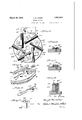
- Fig.1 is a-front elevation of the tool
- Fig/Q is a side'elevation.
- v Fig. 3 is a fragmentary view corresponding generally to that in Fig. '1, with the cutters arranged for preliminarily scraping the valveseat.
- I Fig. 4 is a fragmentary perspective showing one of the cuttersand the accessories for locking the same to the disk.
- i Fig. 5' is a fragmentary perspective showing the mode of applying the. shims, when a the device is employed as a scraper.
- FIG. 6 is a fragmentary sectional elevation showing the relation of one of the cutters and its securing means with respect to the disk.
- Fig. 7 is a similar view showing the cutter arranged with, its scraping edge in opera tive relation.
- Fig. 8 is a fragmentary sectional elevation illustrating the mode of mounting the individual cutters on spacer blocks.
- 7 Fig.9 is a perspective view of one of the U spacer blocks.
- the center of the disk is pro-' vided with asocket 3 by means of which the tool maybe supported inoperative relation,
- a strap or yoke 4 preferably formed of spring steel and having its inner peripheral surface fiattenedto snugly engagethe bottom of the r groove or channel 2.
- One end of the strap 4 isfixedinthe bottomofa block 5 and on the bottom of the block adjacent the anchorage of the strap therein is a toe or fulcrum memher 6 having-an arcuate facealso engaging V the bottom of the groove 2 in thedisk.
- each cutter 21 is of the same generaltype as those employed in the device shown in the patent aforesaid, that is to say, each cutter consists of a bar of steel in the form. ofa triangular prism having three coordinatecutting or dressing edges, or two straight cutting edges, the third being providedwith teeth or serrations, whichpwhen applied in operative position, will scrape'the valve. seat.
- the cutter j bars are. provided on each face with-a longitudinal groove 22, the
- each of the cutters is secured
- each cutter bar will be firmly clamped in position by the engagement of the spline 15 with one of the grooves in the cuttera'nd the engagement of'the associated clamp 18 with another of In Fig; 1, the cutters areqindicated as apthe cutter; grooves, namely, that'in the latera'l face of the cutter bar adjacent the. clamp. r
- spacer blocks are provided, corresponding i-n numher to the cutters, each block having av groove 32 in its bottom to engage a spline 15 on the disk, and a rib or spline 33 on its top, which is adapted to engage the longitudinal groove, in any cutter bar 21 which is mounted on said spacer blOCk,'iI1 the manner 'shownin a screw of sufficient lengthto pass through the opening in the. clamp and a registering opening 31 in thespacerblock and to engage the threaded opening 17 inthe disk 1, is applied in-thefmanner and form shown in Fig.. 8.
- the shims 25 maybe applied between the bottomsof the serrated cutters and the upper faces of the spacer'blocks, each shim straddling the:rib.;33 on the corresponding spacer block, so that these serrated edges" of the cutters will be raised slightly abovethe plane of the straight or plain edges, of the other cutters. 7
- a rotary cutter comprising a disk, a -plu-' rality of cutters carried by one face thereof each comprising a bar of triangular pris matic form provided with longitudinal grooves in its faces, and means for locking the individual cutters to the disk each including' a spline carried by the disk to be engaged by one of the cutter grooves, a clamp having an undercut face to engage a lateral face of the cutter, and a bolt for securing theclamp of each comprising a triangular prismatic bar provided with longitudinal grooves in its faces, andmeans for locking the individual cutters to the disk each includinga spline the cutter grooves, a clamp-having an undercarried-by the disk to be engagedwith one of V face and groove of the cutter, and a bolt for I securing the clamp to the disk.
- A- rotary cutter comprising a disk, a plurality of cutters adapted to be adjustably mounted on one face of the disk each'comprising a triangular prismatic bar provided with longitudinal grooves in its faces, spacer blocks having ribs on their tops to engage the grooves in the bottoms of cuttersmounted thereon and having grooves in their bottoms, splines on the face of the disk engaging the grooves in the bottoms of the blocks, clamps having undercut faces for engaging the lateral faces of cutters on the spacer blocks, and screw bolts engaging registering holes in the clamps, the blocks and the disk to lock the cutters to the blocks and the blocks to the disk.
Landscapes
- Engineering & Computer Science (AREA)
- Mechanical Engineering (AREA)
- Milling Processes (AREA)
Description
1 March 29, ALBEE 1,851,613
ROTARY CUTTER Filed Nov. 14, 1930 I Z Sheets-Sheet l March 29, 1932. H, ALBEE 1,851,613
ROTARY CUTTER Filed Nov. 14, 1930 2 Sheets-Sheet 2 Patented Ma. 29, 1932.
UNITED STATES HUGH M. ALBEE, OF
ORANGE, MASSACHUSETTS, ASSIGNOR To THE IiEAVITT MAoHmri f COMPANY, OF ORANGE, MASSACHUSETTS ROTARY CUTTER.
= Application filed Nvember 14,19 3( Serial ivb.4a5,775..
The invention relates to rotary cutters of the general type shown in Patent No. 1,227,- 514:, dated May 22, 1917 employed for dressing or recutting valve seats and the principal objects of the instant invention are to simplify the supporting and Operating means for the cutter carrying disk, to provide a positive lockingmeans for securing the cutters to'the disks or to spacer blocks carried by the latter, and, generally stated; to provide a rotary cutter ofsimplified construe tion,but materially increased efficiency and durability. The invention is illustrated in the accompanying drawings, in which Fig.1 is a-front elevation of the tool, the
pp r away. 7
.Fig/Q is a side'elevation. v Fig. 3 is a fragmentary view corresponding generally to that in Fig. '1, with the cutters arranged for preliminarily scraping the valveseat. I Fig. 4 is a fragmentary perspective showing one of the cuttersand the accessories for locking the same to the disk. i Fig. 5' is a fragmentary perspective showing the mode of applying the. shims, when a the device is employed as a scraper.
portion of the handle being broken Fig. 6 is a fragmentary sectional elevation showing the relation of one of the cutters and its securing means with respect to the disk.
Fig. 7 is a similar view showing the cutter arranged with, its scraping edge in opera tive relation. y l i I Fig. 8 is a fragmentary sectional elevation illustrating the mode of mounting the individual cutters on spacer blocks. 7 Fig.9 is a perspective view of one of the U spacer blocks. a
Referring to the drawings, lrindicates the rotary cutter head" in the form of a relatively-thin disk provided with agroove or chan- 'nel '2 in its peripheral edge, which channel extends throughout theentire circumference of. the disk and is generally rectangular 1n cross section. The center of the disk is pro-' vided with asocket 3 by means of which the tool maybe supported inoperative relation,
on a suitable cutter bar, as explained inthe patent aforesaid and in the other patents therein referred to. Substantially encircling V the peripheral edge of the disk 1 and engagmg the groove or channel 2 thereinis a strap or yoke 4, preferably formed of spring steel and having its inner peripheral surface fiattenedto snugly engagethe bottom of the r groove or channel 2. One end of the strap 4 isfixedinthe bottomofa block 5 and on the bottom of the block adjacent the anchorage of the strap therein is a toe or fulcrum memher 6 having-an arcuate facealso engaging V the bottom of the groove 2 in thedisk. Ex
tending laterally from theblock 5 are two parallel. shoulders .8 forming a clevis,' in which is pivoted, on a pin 9, the lower por tion of'a lever 10' provided with anup'ward extension. 10f in vthe'form of an operating rod or handle. The portionof the lever below thepivotpoint'is formed with an angularly dlsposed shoulder piece 10,which is perforated to receive the otherend of thestrap 4 which strap end is adjustably locked to the lever 10by aknurled nut engaging the threads on the end of the stran. Disposed between themember 10 of the lever-and the block 5 1S helical spring13, which tends to move the portion of the lever above its 'pivot point outwardly and correspondingly move the lower portion 10' ofthe said lever inwardly,
ereby causing the strap 4 to hug the bottom of the groove'or channel 2 inthe periphery of theldiskwith considerable pressure. so
that. when the lever 10 is swung to the left.
as viewed in Fig.1, afterthe tool is adjusted for dressing or recutting a valve seat the frictional engagement between the strap and the bottom of the peripheral groove 2 will give a partial rotation to the disk. "Movement of the lever in the opposite direction, however, will cause the "lower end of'the lever to vrelease'thetension on the strap, so
that the latter will slide-around the periph-' eral groove and the disk will remain stationary; In the swinging movement of the lever, r
which is effected manually; the toe 6 on the block?) serves as a fulcrum and also as a fric tion shoeassisting in impa rting'a rotary mo: j
tion tothe disk, when the lever ismovedin the direction to tighten the strap about the v shims withdrawn andthe cutters replaced periphery of the' disk, as explained.
The cutters 21 are of the same generaltype as those employed in the device shown in the patent aforesaid, that is to say, each cutter consists of a bar of steel in the form. ofa triangular prism having three coordinatecutting or dressing edges, or two straight cutting edges, the third being providedwith teeth or serrations, whichpwhen applied in operative position, will scrape'the valve. seat.
to remove any incrustations or foreign materials lodged thereon and which mayalsobe employed to take a rough cut fromthe valve seat, if the latter is badly pitted or impaired. The cutter j bars are. provided on each face with-a longitudinal groove 22, the
groove in one face engaging a spline 15 fixed in the groove 16 in the faceof the disk '1 and another, of the grooves 221s adapted to be engaged by a. shoulder 19 formed onthe undercut side of a clamp. or dog 18, which is a r adaptedfto be locked tothe plate in the relationshown inthe drawings by a screw bolt 20' passing through an opening in the clamp and engaging a threaded opening in the disk 17.
As indicated, each of the cutters is secured,
in a similar manner, to one face of the disk and is capable of longitudinal adjustment to operate on valve seats of varying diameters and, inall positions of adjustment, each cutter bar will be firmly clamped in position by the engagement of the spline 15 with one of the grooves in the cuttera'nd the engagement of'the associated clamp 18 with another of In Fig; 1, the cutters areqindicated as apthe cutter; grooves, namely, that'in the latera'l face of the cutter bar adjacent the. clamp. r
plied for the purpose of dressing or recutting va valve seat with-'the's'traight edges of each cutter lying. in a common; plane. which is.
.p'arallel to the surface of the disk 1. It will be Iunderstood,..of course, that any of the edges of therespectiveucutters may be employedin' operating on thevalve seat and,
when itfis desired to scrape the se'ator to i take a preliminary roughcut therefrom,
' Under these circumstances, it is desirable to those cutters having one edge provided with serrations are applied. and clamped to the face ofthe disk so that the serrated edges are directed outward or'toward the work.
elevate these serrated cutting edges above the plane of the straight or plain edges of the other cutters and this is effected by slipping relatively thin shims 'between the face of the cutter adjacent-the disk, which shims straddle the splines "15, but leave enough ofthc latter projecting above the top surface of the shims to engage 'the groove in the bottom of the corresponding cutters,
" as more p, rticularly illustrated in Fig. 7.
After these serrated-cuttershave. done their work, they are released from the-clamps, the
with a straight or plain cuttingedge in op- 'erative relation, so that all of the cutters will then be effective in dressing or imparting the, final cut to the valve seat.
Vhen the tool is employedto-operate upon valve seats that are associated Withacentral- I 1y disposed projection, it will be necessary to: space the cutters from the disk at a sufii-. cient" distance to. bridge the projection and still permit the rotary disk or cutter bar withwhich it is associated to be properly positioned within the .valve casing. To
effect this spacing of the cutters, spacer blocks are provided, corresponding i-n numher to the cutters, each block having av groove 32 in its bottom to engage a spline 15 on the disk, and a rib or spline 33 on its top, which is adapted to engage the longitudinal groove, in any cutter bar 21 which is mounted on said spacer blOCk,'iI1 the manner 'shownin a screw of sufficient lengthto pass through the opening in the. clamp and a registering opening 31 in thespacerblock and to engage the threaded opening 17 inthe disk 1, is applied in-thefmanner and form shown in Fig.. 8. It will be noted that, when the serrated edges of the cutters are to beemployed'and the cutters are mounted on the, spacer blocks 30, the shims 25 maybe applied between the bottomsof the serrated cutters and the upper faces of the spacer'blocks, each shim straddling the:rib.;33 on the corresponding spacer block, so that these serrated edges" of the cutters will be raised slightly abovethe plane of the straight or plain edges, of the other cutters. 7
WhatI claim is: V 1 1. A rotary cutter, comprising a disk, a -plu-' rality of cutters carried by one face thereof each comprising a bar of triangular pris matic form provided with longitudinal grooves in its faces, and means for locking the individual cutters to the disk each including' a spline carried by the disk to be engaged by one of the cutter grooves, a clamp having an undercut face to engage a lateral face of the cutter, and a bolt for securing theclamp of each comprising a triangular prismatic bar provided with longitudinal grooves in its faces, andmeans for locking the individual cutters to the disk each includinga spline the cutter grooves, a clamp-having an undercarried-by the disk to be engagedwith one of V face and groove of the cutter, and a bolt for I securing the clamp to the disk.
3. A- rotary cutter, comprising a disk, a plurality of cutters adapted to be adjustably mounted on one face of the disk each'comprising a triangular prismatic bar provided with longitudinal grooves in its faces, spacer blocks having ribs on their tops to engage the grooves in the bottoms of cuttersmounted thereon and having grooves in their bottoms, splines on the face of the disk engaging the grooves in the bottoms of the blocks, clamps having undercut faces for engaging the lateral faces of cutters on the spacer blocks, and screw bolts engaging registering holes in the clamps, the blocks and the disk to lock the cutters to the blocks and the blocks to the disk.
In testimony whereof I affix my'signature. V
HUGH M. ALBEE.
Priority Applications (1)
| Application Number | Priority Date | Filing Date | Title |
|---|---|---|---|
| US495775A US1851613A (en) | 1930-11-14 | 1930-11-14 | Rotary cutter |
Applications Claiming Priority (1)
| Application Number | Priority Date | Filing Date | Title |
|---|---|---|---|
| US495775A US1851613A (en) | 1930-11-14 | 1930-11-14 | Rotary cutter |
Publications (1)
| Publication Number | Publication Date |
|---|---|
| US1851613A true US1851613A (en) | 1932-03-29 |
Family
ID=23969947
Family Applications (1)
| Application Number | Title | Priority Date | Filing Date |
|---|---|---|---|
| US495775A Expired - Lifetime US1851613A (en) | 1930-11-14 | 1930-11-14 | Rotary cutter |
Country Status (1)
| Country | Link |
|---|---|
| US (1) | US1851613A (en) |
Cited By (4)
| Publication number | Priority date | Publication date | Assignee | Title |
|---|---|---|---|---|
| US3086277A (en) * | 1960-03-29 | 1963-04-23 | Peerless Aluminum Foundry Co I | Abrasive finishing disk |
| US4248555A (en) * | 1979-08-09 | 1981-02-03 | Showa Machine Industries Co., Ltd. | Drill assembly |
| US4285618A (en) * | 1979-10-12 | 1981-08-25 | Shanley Stephen E Jr | Rotary milling cutter |
| US6290436B1 (en) * | 1998-10-27 | 2001-09-18 | Sandvik Aktiebolaget | Cutting insert for rotating cutting tools |
-
1930
- 1930-11-14 US US495775A patent/US1851613A/en not_active Expired - Lifetime
Cited By (4)
| Publication number | Priority date | Publication date | Assignee | Title |
|---|---|---|---|---|
| US3086277A (en) * | 1960-03-29 | 1963-04-23 | Peerless Aluminum Foundry Co I | Abrasive finishing disk |
| US4248555A (en) * | 1979-08-09 | 1981-02-03 | Showa Machine Industries Co., Ltd. | Drill assembly |
| US4285618A (en) * | 1979-10-12 | 1981-08-25 | Shanley Stephen E Jr | Rotary milling cutter |
| US6290436B1 (en) * | 1998-10-27 | 2001-09-18 | Sandvik Aktiebolaget | Cutting insert for rotating cutting tools |
Similar Documents
| Publication | Publication Date | Title |
|---|---|---|
| US1851613A (en) | Rotary cutter | |
| US1335247A (en) | Adjustable parallel | |
| US1612769A (en) | Expansible locking key | |
| US1812452A (en) | Guard device for wood shapers | |
| US2036111A (en) | Scarifying tooth and holder | |
| US1688913A (en) | Cope head for tenoners and the like | |
| US1489577A (en) | Gauge | |
| US1866654A (en) | Wheel, gear, and the like pulling device | |
| US1848418A (en) | Chamfering tool | |
| US2134140A (en) | Inserted cutter blade and mounting therefor | |
| USRE21877E (en) | Tool holder | |
| US2152567A (en) | Chaser for die heads | |
| US1653340A (en) | Nut-splitting tool | |
| US1461514A (en) | Grinding machine | |
| US1325278A (en) | A corpora | |
| US1327356A (en) | Tailstock-clamping mechanism | |
| US1204829A (en) | Woodworking-machine. | |
| US1520969A (en) | Rigid-action scroll and jaw-slide lathe chuck | |
| US2540530A (en) | Cutterhead | |
| US1824494A (en) | Cylinder edge dressing tool | |
| US1467406A (en) | Tubular saw | |
| US1961442A (en) | Tool holder | |
| US927628A (en) | Means for securing movable lathe-stocks. | |
| US1868750A (en) | Reversible die head | |
| US1287053A (en) | Profile cutter-head. |