US1851604A - All metal sanitary partition - Google Patents
All metal sanitary partition Download PDFInfo
- Publication number
- US1851604A US1851604A US445676A US44567630A US1851604A US 1851604 A US1851604 A US 1851604A US 445676 A US445676 A US 445676A US 44567630 A US44567630 A US 44567630A US 1851604 A US1851604 A US 1851604A
- Authority
- US
- United States
- Prior art keywords
- arm
- partition
- latch
- loop
- metal
- Prior art date
- Legal status (The legal status is an assumption and is not a legal conclusion. Google has not performed a legal analysis and makes no representation as to the accuracy of the status listed.)
- Expired - Lifetime
Links
- 238000005192 partition Methods 0.000 title description 16
- 239000002184 metal Substances 0.000 title description 5
- 241000283690 Bos taurus Species 0.000 description 3
- 210000005069 ears Anatomy 0.000 description 3
- 101100114362 Caenorhabditis elegans col-7 gene Proteins 0.000 description 1
- 230000005484 gravity Effects 0.000 description 1
- 150000002500 ions Chemical class 0.000 description 1
- 239000011435 rock Substances 0.000 description 1
Images
Classifications
-
- A—HUMAN NECESSITIES
- A01—AGRICULTURE; FORESTRY; ANIMAL HUSBANDRY; HUNTING; TRAPPING; FISHING
- A01K—ANIMAL HUSBANDRY; AVICULTURE; APICULTURE; PISCICULTURE; FISHING; REARING OR BREEDING ANIMALS, NOT OTHERWISE PROVIDED FOR; NEW BREEDS OF ANIMALS
- A01K1/00—Housing animals; Equipment therefor
- A01K1/0005—Stable partitions
Definitions
- This-"stanchion frame 7 forms the trans *lfin ohject'of the invention is toprovide verseforward partition'of a-battery of stallg. f a partition for stalls that perinits-thecattle divided longzitu'dinally bythe device 'injac-f toda'efpositioned"Withimtlie stall with ease corda'nce withflthe present inv ntion.
- Fi1rth'e'nobjectsofthefinvention areto'p'ro uprights there is secured'a horizontal cross iviiiea partition of'the 'character referred- 'to .rail 9which: is*preferalol 'io rme'd-,.
- the paitition' arm is in es-aw genera 1 y; at i siin '1 in itsmethod ofass'emhly;formed of 1Q'and c0nsistsofan'eldngated piece-ofinet ali all metal parts; so asto he sanitary, and that "The arm 1'0 is mountedtorockFVe-rticailyat; is coiiiparativly inexp'ensiyetomanufacture right angles to the stanchio'nsiippoftT aii dj-in's'ta lll thepforwa'rdend oftliearin lo isa'fi shaped With 'th'e" foregoing and other objects in fitting
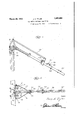
- Fig. 2 is a View similar to Fig, 1 showing Long bolts extend through the fitting-1 1 the partition in down or closed position for the branches,iand thecollars whichi are lioldividing the cows from one another, lo'Wjtnbes, andfextenidl ree-foft'he outer end Fig.
- FIG. 3 is a top plan iew thereof in the ofthe' coll-ars -14fan'd' "15.”
- ThislooltTQWeitdown position, tn'dsthroiig'h apertureson theouterends of1 Fig. i is a detailed vertical section taken hori z'ontal diagonal supportinga ms 21, 2-2 io' 'fsubstantially on the line of Fig. 1, .dispbs'etl'onthe op' osit si'desofth a m I Fig.
- FIG. 5 is a longitudinal fragmentary secs the inner ends*ofthearmsaresecured tion of the partition bar, taken substantially as at 23, a clamping ring-24;that is'disp'osed-' on the line 5.5 of Fig. 3,a. abouttheinterinediate"*p.0rtion*of theifparti- Fig. 6, is a detail vertical section through tion arm 1'0.
- Thei'riilg fll is formed of a I 4'5 'thepartition taken substantially on the singlestrap of irietal with Vertical ext s ang: i line 6-6 of Fig. l.
- An upstanding strap 31 is bolt:
- the inner end of the latch r0d'28 also terminates between these ears, and a single bolt 35 extendsthrough alined'apertures in the ears, the upper end ofthe strap 31 and the fposed aboutthe arm 10 intermediate its ends.
- a stopanenlber is indicated generally at 44. and consists of 'aclevis bo'lt45 disposedabout the lower portion of. the arm- 1-0 andlacross the. legs; of theclevis bolt there is secured.
- L 28 is adapted toslidebetween thelatch 39 and the stop member 44 and itwillbeunder- Torelease the partitions, all thatis neces say to be done, is topress upwardly on the loop 37 to move the arm-up slightly, to free the bolt 37 of the pocket LOuntil it clears the-outer faceofthe latch, whereupon the arm may be released to permit itto move downwardly under theaction of gravity and then the loop willslide inwardly on the arm until it engages the stop member 44 and this engagement of the member 5% by the loop of the machine, will hold the arm 10 in its lowered. position.
Landscapes
- Life Sciences & Earth Sciences (AREA)
- Environmental Sciences (AREA)
- Zoology (AREA)
- Animal Husbandry (AREA)
- Biodiversity & Conservation Biology (AREA)
- Orthopedics, Nursing, And Contraception (AREA)
Description
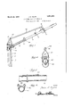
March 29, 1932. J. E. TYLER ALL METAL SANITARY PARTITION Filed April 19, 1930 2 Sheets-Sheet l 7 i 6 In Inventor r, Jeddc E I'j/em A Home y March 29, 1932. E TYLgR 1,851,604
ALL METAL SANITARY PARTITION Filed April 19, 1930 2 Sheets-Sheet 2 Inventor Jaime Z ZJ/Asr A Home y Patented Mar. 29, 1932 i I a '7 i it i V mssEE. I i
snivrraax in wsnrioii i I 7 Application fiiea ir riiis; 1930..]Se ari1t..i4ae7e.
bis-inventionrelates to stalls, and more caliya-tthe forward-endofabatteryiofstalls. particularlytocowstalls; I y This-"stanchion frame 7 forms the trans *lfin ohject'of the invention is toprovide verseforward partition'of a-battery of stallg. f a partition for stalls that perinits-thecattle divided longzitu'dinally bythe device 'injac-f toda'efpositioned"Withimtlie stall with ease corda'nce withflthe present inv ntion. f Thisa 55 and dispateh and'"'a t the same time will re- 'stanchion frame consists iof'aplnrality (after- Inaiirsupp'orted in anypositien'so that the ti cal upri ghtsi anchoredattheii 'owerends sta lis may he" cleaned with ease and economy. to the stable fioor, and acrossthe tops-"i? the" Fi1rth'e'nobjectsofthefinvention areto'p'ro uprights there is secured'a horizontal cross iviiiea partition of'the 'character referred- 'to .rail 9which: is*preferalol 'io rme'd-,. f wo'od-g fiu j that is strong, compact and durable;"thorbut 'iliay bemad'e-ofanydesired njefiivll" ouglily;relia'iil'e forits intended purposeg very The paitition' arm is in es-aw genera 1 y; at i siin '1 in itsmethod ofass'emhly;formed of 1Q'and c0nsistsofan'eldngated piece-ofinet ali all metal parts; so asto he sanitary, and that "The arm 1'0 is mountedtorockFVe-rticailyat; is coiiiparativly inexp'ensiyetomanufacture right angles to the stanchio'nsiippoftT aii dj-in's'ta lll thepforwa'rdend oftliearin lo isa'fi shaped With 'th'e" foregoing and other objects in fitting-11'tothestenrofwhich is' threadably' View, theinven'tion consists-iota novel conconnectedt'he forward endofthe;arm; lL'atg .stifii'ction, combination fandarrangement of eral extensionsfl2;13ers thr'eadably 'coiinects .36 partsaswill be hereina-ifter inore specifically edto the branchesofithe T shapedflfittingQII' described and illustrated 'inHie-accompanyandpn'tiheouter'ends of'ithese e'itens'i'ofrisare ing -'dra'wings, wherein is cflisclosed an emsecured {the outstanding collars 14;L15. V bodinrent of the; invention, but is to he Bearingagaint the inner end-of tli: col- 7 understood fthat' changes, "variations and lars 14 1-5 are the"highti portions of the? U 1nodficat ions andame'ndinents may-heresha'ped hol'ts"16',"17 t-h'e legsofwhich are an 76. sorted towithjout departing 'from thespirit choredf to the top rai19-of-thestanchionsup oi the 'clhiinheret oappendedi r porthi Thus it willbeseen-thatthe arm is "In the drawings "wherein like reference rockableinthe'biglit' po'i-tion'of the clamping v characters" "denote corresponding par-ts bolts. I 3 I throiighoiittheseveralviews? v l The bi'gh'tf offthe stanchion-18k "SWiVeled 'SG I Figure 1 is a side-elevation of 'the in've-nas at 19 -to the undersideoifgthe cross. arm tiiin "applied: to the stanchion support" which and "there one stanchion and one partition is shown inWerticahdetailed section, arm '10 foreabh stall. I 1 y Fig. 2 is a View similar to Fig, 1 showing Long bolts extend through the fitting-1 1 the partition in down or closed position for the branches,iand thecollars whichi are lioldividing the cows from one another, lo'Wjtnbes, andfextenidl ree-foft'he outer end Fig. 3 is a top plan iew thereof in the ofthe' coll-ars -14fan'd' "15." ThislooltTQWeitdown position, tn'dsthroiig'h apertureson theouterends of1 Fig. i is a detailed vertical section taken hori z'ontal diagonal supportinga ms 21, 2-2 io' 'fsubstantially on the line of Fig. 1, .dispbs'etl'onthe op' osit si'desofth a m I Fig. 5 is a longitudinal fragmentary secs the inner ends*ofthearmsaresecured tion of the partition bar, taken substantially as at 23, a clamping ring-24;that is'disp'osed-' on the line 5.5 of Fig. 3,a. abouttheinterinediate"*p.0rtion*of theifparti- Fig. 6, is a detail vertical section through tion arm 1'0. Thei'riilg fll is formed of a I 4'5 'thepartition taken substantially on the singlestrap of irietal with Vertical ext s ang: i line 6-6 of Fig. l. a r 2 5,; '26; on=*the' ends thatkareVprovid In the drawings, wherein for the purpose apertii-res toreeeive tlie'bol't 27 that s'ecuresthe of illustration is shown the preferred embodiplate aflioutftheiarinlfll V E f ,ment of m invention, 7 indicates generally elongated latch r od1285sniouiited ab'ove 50"the'stanch1on frame that is disposed vertithe partition arm 10. h 1
i 1 Arpair of upstanding arms 29, are pivoted at their lower ends to the outer ends of the bolt '20. An upstanding strap 31 is bolt:
ed at its lowerend as at 32 to the upright 8 and this strap inclines rearwardly and terminates in alinement with the upstanding ears 33', 34,0n the upper ends of thearms 29, 30. r
The inner end of the latch r0d'28 also terminates between these ears, and a single bolt 35 extendsthrough alined'apertures in the ears, the upper end ofthe strap 31 and the fposed aboutthe arm 10 intermediate its ends.
Anchoredto the sides of theloop 37 and exa outer end of the latch rod 28, whereby a rock ing bearing is provided for a latch rod 28.
On the inner end of the latch'rod'28 is'se curedby means'of the rivet 36, the upper end of a looped rod of metal 37 that, is. circumtending acrossthe opening thereoflis alatch bolt-[38, and this loop, "is adapted to slide. on the partition bar lO when it is rocked upand, down onitspivot.
. Adj acenttheouter end of the arm 10, there 1 isian upstanding latch indicated generally 3 at 39 and this latch is, formed of a ,fiatpiece of metal bent intermediate itsends to form-a transversepocket and an arcuate forward portion 41, the endlof which is anchoredjm an openingin the arm 10. 7
"Theouter endof the latch 39 is formed V withan integralbolt 42that extends through,
openings inthe arm 10 and isrigidly secured by means .of a nut- 43 on its lower end. 7 A stopanenlber is indicated generally at 44. and consists of 'aclevis bo'lt45 disposedabout the lower portion of. the arm- 1-0 andlacross the. legs; of theclevis bolt there is secured. a
' strap 46 that proj ects laterally of the arm 10.
' by the stanchion 18.
c The loop stood {that the stop member 44 may be adjust ed lengthwise of the arm 10 to fix the limit' of downward movement of the arm.
v Adjacent the outer end of the arm 10, there V is secured a spring clip 47 which the oows tail may be clipped while the cow is being milked. I
r In the operation of the rockable partition arm, it will'be understood that the armis in the down position as shown in Fig.2 ofthe,
H ,37 on the end ofthe latcharm. L 28 is adapted toslidebetween thelatch 39 and the stop member 44 and itwillbeunder- Torelease the partitions, all thatis neces say to be done, is topress upwardly on the loop 37 to move the arm-up slightly, to free the bolt 37 of the pocket LOuntil it clears the-outer faceofthe latch, whereupon the arm may be released to permit itto move downwardly under theaction of gravity and then the loop willslide inwardly on the arm until it engages the stop member 44 and this engagement of the member 5% by the loop of the machine, will hold the arm 10 in its lowered. position. v v v The present embodiment of the'invention hasbeen disclosed-in considerable'detail merel'y forthe' purpose of exemplification, since in actual-practice it attainsthe features of advantage enumerated as desirable in the. statement of the invention, and the above description. v Y 1,
It is to be understood ,thatby' 'describing in detail herein-any particular form, .structure or arrangement, it is notintendedto T 7 limit the, invention beyond the terms oflthei claim, or the requirements; of the prior art.
Having thus described my'inventiom what I claim as new 1s:
' A device of the c prising a forwardtransverse partition la longitudinal partitionbar pivotally connect-1 fed at its forward end to the said partition, "a
latch rod associatedwith the transverse pa k-.1 a tition at one end, an elongated loop-member connected at itsupperend to the-rear endof;
thelatch rod and through which thefbarj i of the loop forenga gement thereby toilimit pass es, an adjustable stoplon the barjin front,
downward. movement of thebar, said stop, consisting of U-m'ember embracing thebar, and a strap having holes thereinthrough which the ends of the limbs of the. U-mem-j ber 'pass,;witl1 nuts on the ends of the limbs for holding the strap :and UJ- member in the bar in rear of the momma bolt onthe loop for engagement withthe latchtohold the bar in raised position.
In testimony whereof I aflix signature;
clamping engagement on "the bar, alatch on [JESSE E; TYLERLf drawings. ,7 In this position the loop'37 bears against the stop-member ift and is supportedin a downwardly inclined position to provide 1 J a partition betweenfthe cows are held To a se the mm a. v to be done, is to lift upwardly on the arm of v the drawings. 7
10, all that, is necessary
Priority Applications (1)
| Application Number | Priority Date | Filing Date | Title |
|---|---|---|---|
| US445676A US1851604A (en) | 1930-04-19 | 1930-04-19 | All metal sanitary partition |
Applications Claiming Priority (1)
| Application Number | Priority Date | Filing Date | Title |
|---|---|---|---|
| US445676A US1851604A (en) | 1930-04-19 | 1930-04-19 | All metal sanitary partition |
Publications (1)
| Publication Number | Publication Date |
|---|---|
| US1851604A true US1851604A (en) | 1932-03-29 |
Family
ID=23769801
Family Applications (1)
| Application Number | Title | Priority Date | Filing Date |
|---|---|---|---|
| US445676A Expired - Lifetime US1851604A (en) | 1930-04-19 | 1930-04-19 | All metal sanitary partition |
Country Status (1)
| Country | Link |
|---|---|
| US (1) | US1851604A (en) |
Cited By (3)
| Publication number | Priority date | Publication date | Assignee | Title |
|---|---|---|---|---|
| US4726154A (en) * | 1985-12-02 | 1988-02-23 | Port-A-Stall | Animal housing system |
| US20070006817A1 (en) * | 2006-05-12 | 2007-01-11 | Komro Sales And Service, Inc. | Animal stall assembly |
| US20080216761A1 (en) * | 2005-11-22 | 2008-09-11 | Maasland N.V. | Cubicle construction and a coupling for such a cubicle construction |
-
1930
- 1930-04-19 US US445676A patent/US1851604A/en not_active Expired - Lifetime
Cited By (3)
| Publication number | Priority date | Publication date | Assignee | Title |
|---|---|---|---|---|
| US4726154A (en) * | 1985-12-02 | 1988-02-23 | Port-A-Stall | Animal housing system |
| US20080216761A1 (en) * | 2005-11-22 | 2008-09-11 | Maasland N.V. | Cubicle construction and a coupling for such a cubicle construction |
| US20070006817A1 (en) * | 2006-05-12 | 2007-01-11 | Komro Sales And Service, Inc. | Animal stall assembly |
Similar Documents
| Publication | Publication Date | Title |
|---|---|---|
| US1851604A (en) | All metal sanitary partition | |
| US1512610A (en) | Sanitary cow stall | |
| US750574A (en) | Twine-holder and tension device for harvesters | |
| US2308213A (en) | Portable and knockdown cattle holder | |
| US1306073A (en) | Clothes-put | |
| US2093732A (en) | Animal gambrel | |
| US1369079A (en) | Food-holder for poultry, &c. | |
| US2939425A (en) | Restraining device | |
| DE298726C (en) | Safety stirrups. | |
| US1557847A (en) | Animal trap | |
| US2132305A (en) | Automobile seat holder | |
| US2620952A (en) | Garment hanger | |
| US242665A (en) | Alexander j | |
| DE947461C (en) | Plaette board | |
| DE370449C (en) | Clothespin made of wood | |
| US597061A (en) | Bag-catcher for postal cars | |
| DE575285C (en) | Hangers | |
| US1460457A (en) | Landmarker for planters | |
| US1894424A (en) | Ironing stand with stabilizing means | |
| US819826A (en) | Stanchion. | |
| US1766028A (en) | Glider | |
| DE1613154U (en) | BOTTLE CHAIR FOR BOTTLE FILLERS. | |
| DE856956C (en) | Clothes hanger with a curved chest | |
| DE354150C (en) | Auxiliary device for hanging up laundry | |
| US1795723A (en) | Sanitary toothbrush holder |