US1851571A - Means for retarding spinning of automobile transmission gears during gear shifting operation - Google Patents
Means for retarding spinning of automobile transmission gears during gear shifting operation Download PDFInfo
- Publication number
- US1851571A US1851571A US425015A US42501530A US1851571A US 1851571 A US1851571 A US 1851571A US 425015 A US425015 A US 425015A US 42501530 A US42501530 A US 42501530A US 1851571 A US1851571 A US 1851571A
- Authority
- US
- United States
- Prior art keywords
- gearing
- retarding
- spinning
- gear shifting
- clutch
- Prior art date
- Legal status (The legal status is an assumption and is not a legal conclusion. Google has not performed a legal analysis and makes no representation as to the accuracy of the status listed.)
- Expired - Lifetime
Links
- 230000005540 biological transmission Effects 0.000 title description 15
- 230000000979 retarding effect Effects 0.000 title description 11
- 238000009987 spinning Methods 0.000 title description 10
- 230000000295 complement effect Effects 0.000 description 5
- 238000010276 construction Methods 0.000 description 5
- OKTJSMMVPCPJKN-UHFFFAOYSA-N Carbon Chemical compound [C] OKTJSMMVPCPJKN-UHFFFAOYSA-N 0.000 description 3
- 229910052799 carbon Inorganic materials 0.000 description 3
- 239000002184 metal Substances 0.000 description 3
- 239000003153 chemical reaction reagent Substances 0.000 description 1
- 239000000463 material Substances 0.000 description 1
- 230000007935 neutral effect Effects 0.000 description 1
- UAJUXJSXCLUTNU-UHFFFAOYSA-N pranlukast Chemical compound C=1C=C(OCCCCC=2C=CC=CC=2)C=CC=1C(=O)NC(C=1)=CC=C(C(C=2)=O)C=1OC=2C=1N=NNN=1 UAJUXJSXCLUTNU-UHFFFAOYSA-N 0.000 description 1
- 229960004583 pranlukast Drugs 0.000 description 1
- 238000000926 separation method Methods 0.000 description 1
Images


Classifications
-
- F—MECHANICAL ENGINEERING; LIGHTING; HEATING; WEAPONS; BLASTING
- F16—ENGINEERING ELEMENTS AND UNITS; GENERAL MEASURES FOR PRODUCING AND MAINTAINING EFFECTIVE FUNCTIONING OF MACHINES OR INSTALLATIONS; THERMAL INSULATION IN GENERAL
- F16D—COUPLINGS FOR TRANSMITTING ROTATION; CLUTCHES; BRAKES
- F16D67/00—Combinations of couplings and brakes; Combinations of clutches and brakes
- F16D67/02—Clutch-brake combinations
-
- Y—GENERAL TAGGING OF NEW TECHNOLOGICAL DEVELOPMENTS; GENERAL TAGGING OF CROSS-SECTIONAL TECHNOLOGIES SPANNING OVER SEVERAL SECTIONS OF THE IPC; TECHNICAL SUBJECTS COVERED BY FORMER USPC CROSS-REFERENCE ART COLLECTIONS [XRACs] AND DIGESTS
- Y10—TECHNICAL SUBJECTS COVERED BY FORMER USPC
- Y10T—TECHNICAL SUBJECTS COVERED BY FORMER US CLASSIFICATION
- Y10T74/00—Machine element or mechanism
- Y10T74/19—Gearing
- Y10T74/19219—Interchangeably locked
- Y10T74/19284—Meshing assisters
Definitions
- This. invention has for its object, means for braking or retarding the rotation or spinning of the rotatable parts of an automobile change speed gearing during gear shifting 15 operationsin order to facilitate the meshing of the shiftable gears with stationary gears, which means is particularly simple and economical in construction, readily embodied in standard forms of transmission gearings, and
- the invention consists in the novel features and in the combinations and constructions hereinafter set forth and clainfed.
- Figure 1 is .a side elevation, partly dia- Figure 3 is a fragmentary, sectional view of the gear housing illustrating another form of the invention.
- Figure 5 is an enlarged longitudinal sectional View illustrating another embodiment of the invention.
- This invention comprises generally, a brake acting on a rotatable part of the automobile transmission gearing, the application of the brake being preferably controlled by the throwing out of the clutch pedal preliminary to gear shifting operations, and also by the temperature or the consistency or thickness of the oil in the gear housing due to its temperature.
- the application of the brake being preferably controlled by the throwing out of the clutch pedal preliminary to gear shifting operations, and also by the temperature or the consistency or thickness of the oil in the gear housing due to its temperature.
- This invention acts on the rotatable parts of the gearing, or those rotatable with the drive shaft of the gearing toretard the rotation thereof in a manner similar to the action of the oilin cold weather.
- the transmission gearing may be of any suitable and well known form, size and construction including the usual housing and rou tatable parts as driving, driven and counter shafts with gears thereon, the gears on one of said shafts, usually the driven shaft, being -sh iftable to produce low, second and direct drive, or third'speed, and also to produce reverse speed.
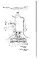
- 1 designates the gear housing. 2 the drive shaft. 3 the transmission or driven shaft, and 4 the counter'shaft.
- the drive shaft 2 is connected in the usual manner to the engine by a normally engaged clutch C, the driven member 5 of which is mounted on the shaft 2 to rotate therewith.
- the clutch is normally held engaged by the usual spring 6 and is thrown out against the action of the spring by the clutch pedal 7.
- the circuit through the coils of the electromagnet is normally open and is closed by a switch preferably operable by the throwing out of the clutch pedal 7 and also by a thermostatically operated switchor circuit closure controlled by the temperature of the oil in the gear housing 1.
- the thermostatically operated device 20 as form, size and construction and is. mounted on the bottom of the gear housing within the housing.
- the wire 19 is connected to the lowermost disk of the pile.
- the wire 18 is connected to the thermostat 22.
- the thermostat is in the form of a leaf secured at one end to a support or post 23 on the bottom of the gear housing, and the free end of the thermostat presses against the uppermost disk of the pile.
- the switch 11 In operation, eliminating for the moment the switch designated generally 24, when the clutch pedal 7 is'operatedto throw out the engine clutch, the switch 11 will be closed and the current will pass from the battery to the coils of the electro-magnet 9 if suflicient resistance is not offered by the carbon pile and when the magnet is energized, it will attract its armature 10 and thus brake or re' tard the rotation of the gearing. If the oil is cold, little or no current will pass through the carbon pile 20. When however, the en- "gine heats up and the oil becomes heated, the
- the speed of the gears will be retarded during gear shiftmg operation.
- the retarding effect is desirable only when shifting up, thatis, from low vided gear to second, and from second to high, and It is not desirable when shifting down from high to second, as is oftentimes desirable when drivin down steep hills, means may be pro for cutting out .the brakingefiect when shifting down from high to second. This means is here shown as a normally closed.
- the high speed shift rod 25 is provided with a cam surface 27 arranged to operate the switch 24 and separate the contacts 28, 29 when the shift rod 25 is in its position assumed when the transmission gearing is in high or direct drive sition.
- Bracket 34 designates a brake shoe having a lining or facing 33 of braking material, this shoe being-carried by a bracket 34 embodying a resilient strip 35 tending to press the shoe toward the shaft 4.
- the bracket 34 is mounted in a suitable guide block 36 mounted upon the bottom of the gear housing and secured thereto as by screws 37 extending throu h a plate 38 on the outside of the bottom 0 the housing and extending through said bottom izo and threading into the block 36.
- a set screw metal having a difierent coeflicient of expansion so that the two act as a thermostat to automatically adjust the pressure of the brake shoe 32. In either case, the set screw is adjusted initially, and in the latter case in which a thermostat is used, the pressure is further controlled by the thermostat.
- the pressureapplied is very means, and in Tigure 1', the thermostatic means is used in conjunction with the clutch pedal.
Landscapes
- Engineering & Computer Science (AREA)
- General Engineering & Computer Science (AREA)
- Mechanical Engineering (AREA)
- Gear-Shifting Mechanisms (AREA)
Description
March 29, 1932. Q DQMAN MEANS FOR RETARDING SPINNING 0F AUTOMOBILE TRANSMISSION GEARS DURING GEAR SHIFTING OPERATION Filed Jan. 51, 1930 3 Sheets-Sheet INVENTOR fir v I ATTOR N EYS March 29, 1932. c, DOMAN 1,851,571
MEANS FOR RETARDING SPINNING OF AUTOMOBILE TRANSMISSION GEARS DURING GEAR SHIFTING' OPERATION Filed Jan. 31, 1930 y 3 Sheets-Sheet 2 unuHlhTlhl INVENTOR BY 142% g ATTORNEYS.
March 29, 1932. c DQMAN 1,851,571
MEANS FOR RETARDING SPINNING OF AUTOMOBILE TRANSMISSION GEARS DURING GEAR SHIFTING OPERATION I Filed Jan. 51, 1950 5 Sheets-Sheet 3 INVENTOR ATTORNEY5 Patented a9, 1932' 7 UNITED STATES PATENT OFFICE CARL DOMAN, OI SYRACUSE, NEW YORK, ASSIGNOR '10 FRANKLIN DEVELOPMENT CORPORATION, OF SYRACUSE, NEW YORK, A CORPORATION OF NEW YORK Y mums ron RETABDING srnmmo or AUTOMOBILE 'rmnsmssron ems Donnie em smr'rmo OPERATION Application filed January 81, 1930. Serial No. 425,015. I
This. invention has for its object, means for braking or retarding the rotation or spinning of the rotatable parts of an automobile change speed gearing during gear shifting 15 operationsin order to facilitate the meshing of the shiftable gears with stationary gears, which means is particularly simple and economical in construction, readily embodied in standard forms of transmission gearings, and
highly eflicient and durable in use.
The invention consists in the novel features and in the combinations and constructions hereinafter set forth and clainfed.
In describing this invention, reference is had to the accompanying drawings in which like characters designate corresponding parts in all the views.
Figure 1 is .a side elevation, partly dia- Figure 3 is a fragmentary, sectional view of the gear housing illustrating another form of the invention.
' Figure 1 is an enlarged sectional view on line 4-4=, Figure 3.
Figure 5 is an enlarged longitudinal sectional View illustrating another embodiment of the invention.
This invention comprises generally, a brake acting on a rotatable part of the automobile transmission gearing, the application of the brake being preferably controlled by the throwing out of the clutch pedal preliminary to gear shifting operations, and also by the temperature or the consistency or thickness of the oil in the gear housing due to its temperature. In cold weather, when the oil is thick, gear shifting without clashing of the gears, is particularly easy, as the thick cold oil retards spinning of the gears when the main clutch is thrown out. When the oil becomes heated, as it does after the automobile has been run, the oil becomes thinner.
This invention acts on the rotatable parts of the gearing, or those rotatable with the drive shaft of the gearing toretard the rotation thereof in a manner similar to the action of the oilin cold weather.
The transmission gearing may be of any suitable and well known form, size and construction including the usual housing and rou tatable parts as driving, driven and counter shafts with gears thereon, the gears on one of said shafts, usually the driven shaft, being -sh iftable to produce low, second and direct drive, or third'speed, and also to produce reverse speed.
1 designates the gear housing. 2 the drive shaft. 3 the transmission or driven shaft, and 4 the counter'shaft. The drive shaft 2 is connected in the usual manner to the engine by a normally engaged clutch C, the driven member 5 of which is mounted on the shaft 2 to rotate therewith. The clutch is normally held engaged by the usual spring 6 and is thrown out against the action of the spring by the clutch pedal 7. v
8 designates the fly wheel of the engine. In Figures 1 and 2, the brake for retarding the rotation of the transmission gears is shown as an electro-magnetic brake.
9 designates the coils of an electro-magnet supported by the gear housing concentric with the drive shaft 2, and 10 is an annular armature mounted in juxtaposition to the electro-magnet 9, this armature being mounted on and rotatable with the shaft 2, but having a slight movement axially of the shaft.- The circuit through the coils of the electromagnet is normally open and is closed by a switch preferably operable by the throwing out of the clutch pedal 7 and also by a thermostatically operated switchor circuit closure controlled by the temperature of the oil in the gear housing 1.
11 designates the casing of a'normally open switch mounted on the gear housing and including a movable member 12 which is connected by a link 13 to the clutch pedal 7. One terminal 1401? the switch is connect-ed by a wire 15 to one side of the battery 16, and the other terminal 17 is connected to the coils of the electro-magnet 9 through wires 18 and 19 connected together through a thermostatically operated circuit closer subject to Lou the temperature of the oil the gear hous- 1 mg The thermostatically operated device 20 as form, size and construction and is. mounted on the bottom of the gear housing within the housing. The wire 19 is connected to the lowermost disk of the pile. The wire 18 is connected to the thermostat 22. The thermostat is in the form of a leaf secured at one end to a support or post 23 on the bottom of the gear housing, and the free end of the thermostat presses against the uppermost disk of the pile.
In operation, eliminating for the moment the switch designated generally 24, when the clutch pedal 7 is'operatedto throw out the engine clutch, the switch 11 will be closed and the current will pass from the battery to the coils of the electro-magnet 9 if suflicient resistance is not offered by the carbon pile and when the magnet is energized, it will attract its armature 10 and thus brake or re' tard the rotation of the gearing. If the oil is cold, little or no current will pass through the carbon pile 20. When however, the en- "gine heats up and the oil becomes heated, the
temperature of the oil will cause the-thermostat 22 to press the disks of the carbon pile 21 together so that there is little resist ance offered to the current and hence, each time the main clutch is thrown out by de pressing the pedal 7, the electro-magnet 9 will be energized and retard the rotation of the gears.
As the clutch is thrown out preliminary to gear shifting operations, the speed of the gears will be retarded during gear shiftmg operation. As the retarding effect is desirable only when shifting up, thatis, from low vided gear to second, and from second to high, and It is not desirable when shifting down from high to second, as is oftentimes desirable when drivin down steep hills, means may be pro for cutting out .the brakingefiect when shifting down from high to second. This means is here shown as a normally closed.
switch 24 in the circuit betweenthe battery 16 and the switch 11 and operable to 0 en position when the gear is shifted into t ird or high speed gearso that when it is desired to shift from high to second, the closing of the switch 11 will not close the circuit through the magnetic brake as the circuit is held open by the switch 24 and therefore, as the shift is made very quickly, little or no retarding effeet will take place while the shift is being ally have two shdable shift rods as 25, one
of which is selected and used when shifting into reverse gear and low gear, and theother of which isselected and used whenshifting' into second, or into high. These rods are operated by the usual selecting and shifting lever'26, all as will be understood by those skilled in the art. The high speed shift rod 25 is provided with a cam surface 27 arranged to operate the switch 24 and separate the contacts 28, 29 when the shift rod 25 is in its position assumed when the transmission gearing is in high or direct drive sition.
When in this position, if it is desire to shiftinto second,depression of the foot pedal 7 will close the switch 11, but the electric circuit to the electro-magnetic brake 9 will be open owing'to the separation of the contacts 28 29 of'the switch 24.
Therefore, no retarding effect takes place when the clutch pedal 7 is'thrown out. The
shifting of the gears is effected almost instantl and is com fileted before any retarding e ect will be e ective due to the 010 of the contacts 28 and 29 when the high spee shift rod 25 reaches neutral position and the cam 27 moves out of engagement with the switch 24.
In Figure 2, a construction is shownin which the switch 24 and its function is omitted,'and also in which the thermostatically operated switch is omitted, the terminals of the switch 11 being connected by awire 30 directly to the coils 9 of the electro-magnet and by a wire 31 to the battery. In Figure 2, upon each depression of the pedal 7, the electro-magnet 9 will be energized and a retarding efi'ect takes place whether shifting up or down through the speed changes.
In Figures 3 and 4, a brake is shown applied directl to the countershaft 4, this being constant y applied.
32 designates a brake shoe having a lining or facing 33 of braking material, this shoe being-carried by a bracket 34 embodying a resilient strip 35 tending to press the shoe toward the shaft 4. i The bracket 34 is mounted in a suitable guide block 36 mounted upon the bottom of the gear housing and secured thereto as by screws 37 extending throu h a plate 38 on the outside of the bottom 0 the housing and extending through said bottom izo and threading into the block 36. A set screw metal having a difierent coeflicient of expansion so that the two act as a thermostat to automatically adjust the pressure of the brake shoe 32. In either case, the set screw is adjusted initially, and in the latter case in which a thermostat is used, the pressure is further controlled by the thermostat. The brake shoe lpresses directly against the periphery of t e shaft 4 and although a lining or facing 33 is used, a metal to metal contact may be used. The pressureapplied is very means, and in Tigure 1', the thermostatic means is used in conjunction with the clutch pedal.
What I claim is:
1. The combination with an automobile change speed transmission gearing comprising a housing and the usual complement of shafts and shiftable gears in the housing, and the engine clutch including a shiftable clutch section connected to the drive shaft of the gearing and shiftable to disconnect the gear-' ing from the engine and operable to disconnect the gearing from the engine preliminary to gear shifting operations, of a magnbtic brake acting on a rotatable part of the gearing to restrain spinning of the rotatable parts of the gearing during gear shifting operations when the engine clutch is thrown out,
2. The combination with an automobile change speed transmission gearing comprising a housing and the usual complement of shafts and shiftable gears, and the engine clutch including a shiftable clutch section connected to the drive shaft of the gearing and shiftable to disconnect the gearing from the engine and operable to disconnect the gearing from the engine preliminary to gear shifting operations, of a brake acting on a rotatable part of the gearing to restrain spinning of the rotatable parts of the gearing during gear shifting operations when the engine clutch is thrown out, and means controlled by the temperature of the'oil in the gear housing for controlling the application of the brake.
3. The combination with an automobile change speed transmissiongearing comprising a housing and the usual complement of shafts and shiftable gears, and the engine clutch including a shiftable clutch section connected to the drive shaft'of the gearing and shiftable to disconnect the gearing from the engine and operable to disconnect the gearing from the engine preliminary to gear gine c utc is thrown out, and means includ 1e parts of the gearing ing a thermostat subject to the temperature of the oil in the gear housing for controlling the application of the brake. v
4. The combination with an automobile change speed transmission gearing comprising a housing andthe usual complement of shafts and shiftable gears, and the engine clutch including a shiftable clutch section connected to the drive shaft of the gearing and shiftable to disconnect the gearing from;
the engine and operable to disconnect the gearing from the engine preliminary to gear shiftingoperations, of a brake acting on the rotatable part of the gearing to restrain spinning of the rotatable parts of the gearing during gear shifting operations when the engine clutch is thrown out, an electro magnetic rake acting on a rotatable part of the gearing, an electric circuit having a normally open switch therein operable into closed position by the throwing out of the clutch.
5. The combination with an automobile change speed transmission gearing comprising a housing and the usual complement of shafts and shiftable gears, and the engine clutch including a shiftableclutch section connected to the drive shaft of the gearing and shiftable to disconnect the gearing from the engine and operable to disconnect the gearing from the engine preliminary to gear tatable part of the gearing to restrain spinning of the rotatable parts of, the gearing during gear shifting operations when the engine clutch is thrown out, an electro-magnetic brake acting on the rotatable part of the gear shifting operations, of a brake acting on a ro change speed transmission gearing comprisgear shifting operations when the engine clutch is thrown out, an electromagnetic brake acting on a rotatable part of the gear- 4 v a reagent ing, an electric circuit having a normally open switch therein operable into closed position by the throwing out of the clutch, and a ond normally, closed switch in said circui 5 and operable to open POSitlOD by the shifting of the gearing into high speed position. In testimony whereof, I have hereunto signed m name, at Syracuse, in the county 0 Onon a? and State of New York, this 10 28th day 0 January, 1930.
, CARL 130mm.
Priority Applications (1)
| Application Number | Priority Date | Filing Date | Title |
|---|---|---|---|
| US425015A US1851571A (en) | 1930-01-31 | 1930-01-31 | Means for retarding spinning of automobile transmission gears during gear shifting operation |
Applications Claiming Priority (1)
| Application Number | Priority Date | Filing Date | Title |
|---|---|---|---|
| US425015A US1851571A (en) | 1930-01-31 | 1930-01-31 | Means for retarding spinning of automobile transmission gears during gear shifting operation |
Publications (1)
| Publication Number | Publication Date |
|---|---|
| US1851571A true US1851571A (en) | 1932-03-29 |
Family
ID=23684789
Family Applications (1)
| Application Number | Title | Priority Date | Filing Date |
|---|---|---|---|
| US425015A Expired - Lifetime US1851571A (en) | 1930-01-31 | 1930-01-31 | Means for retarding spinning of automobile transmission gears during gear shifting operation |
Country Status (1)
| Country | Link |
|---|---|
| US (1) | US1851571A (en) |
Cited By (15)
| Publication number | Priority date | Publication date | Assignee | Title |
|---|---|---|---|---|
| US2550545A (en) * | 1949-03-11 | 1951-04-24 | Eaton Mfg Co | Countershaft brake |
| US2627957A (en) * | 1950-06-20 | 1953-02-10 | Nat Company Inc | Shaft positioning apparatus |
| US3309934A (en) * | 1964-06-10 | 1967-03-21 | Mack Trucks | Gear transmission oil pump and countershaft brake mechanism |
| US4838818A (en) * | 1986-07-16 | 1989-06-13 | The Eska Company | Friction steering drive system for electric fishing motors |
| US4844223A (en) * | 1987-01-22 | 1989-07-04 | Deere & Company | Arrangement for braking a gearbox component |
| US5413317A (en) * | 1993-04-22 | 1995-05-09 | Prince Corporation | Damping device |
| WO2004069621A1 (en) * | 2003-02-04 | 2004-08-19 | Volvo Lastvagnar Ab | Shaftbrake for stagegeared motor vehicle gearbox where at a first brake element is integrated with and constitutes part of the shaft |
| US20050163855A1 (en) * | 2004-01-27 | 2005-07-28 | Cj Corporation | Method of preparing low-crystallinity oltipraz or amorphous oltipraz |
| US20050217966A1 (en) * | 2004-01-20 | 2005-10-06 | Eaton Corporation | Electromagnetic brake for a multiple-ratio power transmission in a vehicle powertrain |
| WO2005080819A3 (en) * | 2004-01-20 | 2006-04-06 | Eaton Corp | Clutch brake |
| US20060154788A1 (en) * | 2004-01-20 | 2006-07-13 | Eaton Corporation | Control for an electromagnetic brake for a multiple-ratio power transmission in a vehicle powertrain |
| US20070095625A1 (en) * | 2004-01-20 | 2007-05-03 | Eaton Corporation | Electromagnetic inertia brake for a power input shaft of a power transmission mechanism |
| US20070293369A1 (en) * | 2004-01-20 | 2007-12-20 | Eaton Corporation | Control for an electromagnetic brake for a multiple-ratio power transmission that has a neutral switch for power take-off engagement |
| US20080045383A1 (en) * | 2004-01-20 | 2008-02-21 | Eaton Corporation | Control for an electromagnetic brake for a multiple-radio power transmission that has a brake actuation counter |
| US20100243403A1 (en) * | 2009-03-27 | 2010-09-30 | Eaton Corporation | Electromagnetic Inertia Brake for a Multiple-Ratio Power Transmission |
-
1930
- 1930-01-31 US US425015A patent/US1851571A/en not_active Expired - Lifetime
Cited By (27)
| Publication number | Priority date | Publication date | Assignee | Title |
|---|---|---|---|---|
| US2550545A (en) * | 1949-03-11 | 1951-04-24 | Eaton Mfg Co | Countershaft brake |
| US2627957A (en) * | 1950-06-20 | 1953-02-10 | Nat Company Inc | Shaft positioning apparatus |
| US3309934A (en) * | 1964-06-10 | 1967-03-21 | Mack Trucks | Gear transmission oil pump and countershaft brake mechanism |
| US4838818A (en) * | 1986-07-16 | 1989-06-13 | The Eska Company | Friction steering drive system for electric fishing motors |
| US4844223A (en) * | 1987-01-22 | 1989-07-04 | Deere & Company | Arrangement for braking a gearbox component |
| US5413317A (en) * | 1993-04-22 | 1995-05-09 | Prince Corporation | Damping device |
| US20050252731A1 (en) * | 2003-02-04 | 2005-11-17 | Volvo Lastvagnar Ab | Shaftbrake for stagegeared motor vehicle gearbox where at a first brake element is integrated with and constitutes part of the shaft |
| WO2004069621A1 (en) * | 2003-02-04 | 2004-08-19 | Volvo Lastvagnar Ab | Shaftbrake for stagegeared motor vehicle gearbox where at a first brake element is integrated with and constitutes part of the shaft |
| US7681704B2 (en) | 2004-01-20 | 2010-03-23 | Eaton Corporation | Electromagnetic inertia brake for a power input shaft of a power transmission mechanism |
| US7597651B2 (en) | 2004-01-20 | 2009-10-06 | Eaton Corporation | Control for an electromagnetic brake for a multiple-ratio power transmission in a vehicle powertrain |
| WO2005080819A3 (en) * | 2004-01-20 | 2006-04-06 | Eaton Corp | Clutch brake |
| US20060154788A1 (en) * | 2004-01-20 | 2006-07-13 | Eaton Corporation | Control for an electromagnetic brake for a multiple-ratio power transmission in a vehicle powertrain |
| US8265843B2 (en) | 2004-01-20 | 2012-09-11 | Eaton Corporation | Control for an electromagnetic brake for a multiple-ratio power transmission that has a brake actuation counter |
| US20070095625A1 (en) * | 2004-01-20 | 2007-05-03 | Eaton Corporation | Electromagnetic inertia brake for a power input shaft of a power transmission mechanism |
| US20070293369A1 (en) * | 2004-01-20 | 2007-12-20 | Eaton Corporation | Control for an electromagnetic brake for a multiple-ratio power transmission that has a neutral switch for power take-off engagement |
| US7318515B2 (en) | 2004-01-20 | 2008-01-15 | Eaton Corporation | Electromagnetic brake for a multiple-ratio power transmission in a vehicle powertrain |
| US20080045383A1 (en) * | 2004-01-20 | 2008-02-21 | Eaton Corporation | Control for an electromagnetic brake for a multiple-radio power transmission that has a brake actuation counter |
| US20050217966A1 (en) * | 2004-01-20 | 2005-10-06 | Eaton Corporation | Electromagnetic brake for a multiple-ratio power transmission in a vehicle powertrain |
| US8057358B2 (en) * | 2004-01-20 | 2011-11-15 | Eaton Corporation | Control for an electromagnetic brake for a multiple-ratio power transmission that has a brake actuation counter |
| US20110218721A1 (en) * | 2004-01-20 | 2011-09-08 | Eaton Corporation | Control for an Electromagnetic Brake for a Multiple-Ratio Power Transmission that has a Brake Actuation Counter |
| US7846064B2 (en) | 2004-01-20 | 2010-12-07 | Eaton Corporation | Control for an electromagnetic brake for a multiple-ratio power transmission that has a neutral switch for power take-off engagement |
| US20050163855A1 (en) * | 2004-01-27 | 2005-07-28 | Cj Corporation | Method of preparing low-crystallinity oltipraz or amorphous oltipraz |
| CN101189446B (en) * | 2005-06-02 | 2012-09-05 | 伊顿公司 | Electromagnetic brake for a multiple-ratio power transmission in a vehicle powertrain |
| WO2006129186A1 (en) * | 2005-06-02 | 2006-12-07 | Eaton Corporation | Electromagnetic brake for a multiple-ratio power transmission in a vehicle powertrain |
| CN101398048B (en) * | 2007-09-12 | 2013-03-06 | 伊顿公司 | Electromagnetic brake, control system and control method thereof |
| US20100243403A1 (en) * | 2009-03-27 | 2010-09-30 | Eaton Corporation | Electromagnetic Inertia Brake for a Multiple-Ratio Power Transmission |
| US8397893B2 (en) | 2009-03-27 | 2013-03-19 | Eaton Corporation | Electromagnetic inertia brake for a multiple-ratio power transmission |
Similar Documents
| Publication | Publication Date | Title |
|---|---|---|
| US1851571A (en) | Means for retarding spinning of automobile transmission gears during gear shifting operation | |
| US2847956A (en) | Sewing machine needle positioning means | |
| US1491426A (en) | Electromagnetic clutch | |
| US2547131A (en) | Electromagnetic relay | |
| US2714435A (en) | Variable speed transmission devices | |
| US2306645A (en) | Control switch for synchronized clutch mechanisms | |
| US2056690A (en) | Counter mechanism | |
| US3704770A (en) | Adjustable time delay electromagnetic clutch | |
| US2241334A (en) | Automatic transmission | |
| US2585437A (en) | Overdrive control | |
| US2529913A (en) | Domestic appliance | |
| US2098716A (en) | Transmission mechanism | |
| US3244841A (en) | Oven temperature control system | |
| US2860528A (en) | Electromagnetically controlled transmission | |
| US2897309A (en) | Speed-responsive switch mechanism | |
| US1268269A (en) | Gear-synchronizer. | |
| US2305974A (en) | Magnetic coupling | |
| GB540617A (en) | Engine starting mechanism | |
| US2761538A (en) | Electromagnetic controls | |
| US1826929A (en) | Magnetic clutch | |
| US1973603A (en) | Cycle timer for controlling work circuits | |
| US2696580A (en) | Reversible motor control | |
| US2408369A (en) | Motor control | |
| GB378314A (en) | Mechanical device responsive to temperature variations | |
| US1781561A (en) | Electric-switch-operating mechanism |