US1851546A - Revolving door depository - Google Patents
Revolving door depository Download PDFInfo
- Publication number
- US1851546A US1851546A US460844A US46084430A US1851546A US 1851546 A US1851546 A US 1851546A US 460844 A US460844 A US 460844A US 46084430 A US46084430 A US 46084430A US 1851546 A US1851546 A US 1851546A
- Authority
- US
- United States
- Prior art keywords
- door
- receptacle
- depository
- opening
- wall
- Prior art date
- Legal status (The legal status is an assumption and is not a legal conclusion. Google has not performed a legal analysis and makes no representation as to the accuracy of the status listed.)
- Expired - Lifetime
Links
- 238000005192 partition Methods 0.000 description 19
- 230000000875 corresponding effect Effects 0.000 description 12
- 238000010276 construction Methods 0.000 description 5
- 230000002093 peripheral effect Effects 0.000 description 5
- 241000182988 Assa Species 0.000 description 1
- ONIBWKKTOPOVIA-BYPYZUCNSA-N L-Proline Chemical compound OC(=O)[C@@H]1CCCN1 ONIBWKKTOPOVIA-BYPYZUCNSA-N 0.000 description 1
- 238000009825 accumulation Methods 0.000 description 1
- 229940000425 combination drug Drugs 0.000 description 1
- 238000000151 deposition Methods 0.000 description 1
- 238000007599 discharging Methods 0.000 description 1
- 150000002500 ions Chemical class 0.000 description 1
- 239000002184 metal Substances 0.000 description 1
- 229920000136 polysorbate Polymers 0.000 description 1
- 235000002020 sage Nutrition 0.000 description 1
- 230000035939 shock Effects 0.000 description 1
Images


Classifications
-
- E—FIXED CONSTRUCTIONS
- E05—LOCKS; KEYS; WINDOW OR DOOR FITTINGS; SAFES
- E05G—SAFES OR STRONG-ROOMS FOR VALUABLES; BANK PROTECTION DEVICES; SAFETY TRANSACTION PARTITIONS
- E05G7/00—Safety transaction partitions, e.g. movable pay-plates; Bank drive-up windows
- E05G7/001—Bank depositories
Definitions
- the invention relates to a rotating night depository which is intended to be locatedin a ticket office,bankor store, or convenient to any point whereconsiderable sums of cash or the equivalent are received in the form of r numerous relatively small and trequent payments.
- the device of the invention is uti lized in connection with a chest or other burglarproot enclosure whichis preferably beneath the ticket'o'llice, bank or store, or other
- the pocliet or receptacle in the preferred form is carried on. and rotates with the revolving door, which closes the depository.
- the-re is a wall between the door and the receptacle, the door and wall being registering openings, the opening in the .wall being at the top and the open topof the receptacle being disposed toward the door opening.
- a. passage leads downwardly into the chest. 'The entrance to this passage is inside the depository at the bottom and the pocket or receptacle within the depository immediatelyoverlies the entrance to said passage, closing it when the door is open.
- The. said receptacle or pocket is inverted when the revolving door is closed, whereby the articles deposited in the receptacle which are usually money or other valuables, are dropped into the chest or other burglarproof storage space.
- the depository may be made accessible to one employee or class of employeeswho are'peristed to deposit valuables in the receptacle and remove them there-fromduring business hours, the accumulation ofvaluables in the receptacle when finally dropped intothe chest being accessible byway of thechest door-only .and to whomever maybe trusted with the key or combi nation which is separate and distinct from thatto therevolving door whichggives accessto the'depository.
- the product being known commercially as a rotating night depository or rotatingdepository;
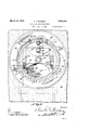
- Figure 1 is a vertical longitudinal section through the revolving depository taken on the line 'ofthe longitudinal axis which is the axis of the rotating door. It shows the revolving door closed and the receptacle in discharging position in which the articles therein are dropped into thechest, M
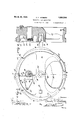
- Figurefi is a front'elevation of the de-" lpositor bl'lQ IlGOI' being closed and certain underlying parts being. shown in broken lines.
- Figure 3 is a rear elevation of-the door removed, the door beingstill shown in closed position with the-opening at the bottom.
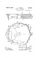
- Figureb is airont elevation of. theremovable partition immediately in the rear of the door. o
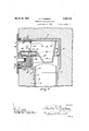
- Figure 6 is a section through Figure 7 isja figure corresponding" to Figure 1 showing the revolving door open and the receptacle in upright position closing the pas- Figure. 4 is an axi'alsection through the; v
- Figure Si a sectional view through the concrete baseshowing the depository'and chest suitably connected.
- a depository casmg 1 This may be of any preferredishape
- This door is mounted in a circularjamb 14 comprising a circular groove 15 andaoircular rib 17 on the'outside of the grooveand forming its side wall on the side toward the outer opening 3.
- the door is formed like the revolving chest door in my copendingapplication No. 340,934, filed Feb.18,1929, as, 'to'its peripheral edge with a circular or peripheral rib, 16,'wl1ich is cutaway at intervals forming spaces as indicated at 18.
- rib 1'? on the depository body or safe proper surroundingthe door opening 'andforming partofthe door jamb is also cut away forming spaces or intervals 19,F1gure 2, corresponding to the sections of 1ib16, each space 19 being slightly longer than the corresponding section of rib 16, so that in one position of the door it may be freelyinserted and removed.
- T he sections of the rib 16 on the door 'in thisjposition of entry and' removal pass through the intervals 19 betweenthe sections of the rib 1? on the door jamb, t-he'spaces 18 "between the rib sections on' the door being long enough, i; e., slightly longer than the corresponding sections of ribs 17 on the jamb, to pass the sections of the rib 17 "on the door jamb.
- the removable wall or partition 24 is grooved at 21 on each side below the door openingand on circular arcs of aradius cor- :respondingfto-the'position oft-the pin and -concentriowith the axis of the door12;
- each groove 21 to limit the to tation of the door and to prevent it from-rot'atin'g'freely, to released position and'toprevent an undue noise and shock to the parts "whenjthe door reaches the end 'ofits swing "in either directiomspring stops 22 are pro- 'vided.
- The'se consist of springs 25seated in ⁇ holes 26,1 for-med inthe partition for this purpose and extending downwardly from the lower end of each groove 21.
- each said spring is enclosed at the upperend in a partially hol-- low plunger27,thesolidend of which is turned upwardly toward the'stop pin 20. The lower endof the spring restson the bottomvof the hole 26. Holes 26 provide for theentrance of the drill in making holes 26.
- the opening 3 in the cylindrical depository casing'1,' is closed by a removablewall or partition 24 immediately back of the door 12, and therefore between the revolving door 12. and the depository receptacle 28;
- the depository casing 1 is provi'dedin therear of groove'15'in the jamb 14 with an inwardly projecting arcuate rib 31 formed in sections and spaced similarly to the spac- Y
- This partition 24, which 1s of thick and 1 highly resistive metal, is circular'in-outline' ing of the sections of the rib 16 on the door -e jamb or otherwise so that the length and 1 spacing of the sections of the rib 31 surround ing the circular opening in the depository or "casing 1 provides that the wallor partition 24 may be passed through'the door jamb'lt and seated immediately behind the'door as shown'in Figure 1, said sections ofthe rib 30 on the removable wall being seated in groove 69 inthe depository casing and intermeshing' with the sections of the, rib 31 011 the casing to prevent the wall 24 from being removed,
- the removable wall or partition 24 is providedat its axial center,wh'ich in operative position of theparts registers with th-eaxial center of the revolving door 12, with a bearing'36 seatedi-n ahole 36' in the wall 24.
- This" bearing is shown as inthe form of a roller bearing, the rollers or pins beingheld in position'by suitable spring detent rings 37, and in 'thisbearing the depository shaft 38*is rotatably mounted
- This shaft has: its iniddle portion 39 within'said bearing of circula'r crosssection and cylindrical form, the
- the door 12 is. provided with a suitable handhole or-door' opening 45 preferably on one side of the center and shown as occupying somewhat less than one half the area of the door.
- The-removable wall or V partition 24 is provided with a handhole or door opening already referred to, which is preferably of exactly similar out'llne and similarlyplaced relatively to the common axis of the door 12, and the partition or'wall '24. Itwill be'understood that in the open position of the door asl'in the structure described in the copending application, the opening in thedoor registers with the openingin ithewallorlpartition 24, andit is like.-
- the depository receptacle28 which is open at the top be .so placed in relation to the handhole or opening' 5 in the revolving door '12, that when the revolving door is'turned to -the position described in vwhich the opening therein registers with the handhole opening 35 in thewall 3e, thedepositoryreceptacle28' is located in V convenient receiving relation" to and preferably beneath said grommelng openings, the
- front of the receptacle- is preferably open and curved as to its top edge or opening-73 to conform to and register with the zhandhole openings or door openings, 35, 45,which are shown as of somewhat fiat curvature at 49 on the side of said openings toward the center, which side is" downward in open posi tion, e., registering with the correspond ing edge 7 3 of the receptacle28.
- Inithispo- I sition the receptacle 28 is not only in receiving position in which the articles which it is desired to deposit can be conveniently :inserted therein by. the hand of the*operator,
- the receptacle 28 rofates. with the door, and the closed position of the doorand receptacle being at 180 de-- 'grees fromthe' open position, thelatter'iis inverted directly over the opening 4:, leading"? .mto the chest so thatthe cash or money and anther: article's deposited n the receptacle are thus discharged into the chest the 0 en" rect-ly in vertical alignment with the opening?
- the disclosure also includes a bolt-53, Fig- 99 ure 3, mounted in suitable slots-54, 55 in the door, and n ormally. advanced spring56,
- the receptacle 28 12 mesh exactly not only with'the openings be- 7 tween the'sections of the rib 17 forming part 7 of the ja1nb,but also with the'spaces between I H lnthisposition thereceptacle closes the openthe sections of the rib 31 just beyond the door jainb, which serveto hold the wan 24 in "its finalposition.
- the sections'of the rib 17 exactly .register with the sections of; the rib 31, so that the wall-24: may be thrust directly backs ward into positionowitli its rib"30, o'ccup yijng the groove 69 ontheinside of theldepository or casing l.
- the door 12 follows the :wall
- the wall member 2-1 being later rotated to the gleftvor contra clockwise through an arc of -aboutv'9O degrees, attains itsfinal position in which it is shown, and when the door is openedthe screws 33 may be'driven through 7 the marginal portion '34 or partition 24' into on thewall with the sections of the rib 31 the cylindrical wall of-the depository casing 1. ;
- the wall 24 is thus held in position by the interm'eshing of'the sections of the rib on the inside of the casing 1.
- Thescrews 33 being inaccessible except when the revolving door to be described is open, present a sufiiv cientlobsta'cle to the rotation and removal of a this vwall member by any unauthorized person.
- the door enters thesjam'b in the same angular position as that 1n Which the part tion was inserted so that the section of the-rib :16 on the door passes through the longspace .69 between the sections of the rib 17 of the, door jamb.v
- the door may be thrust forwardly, i. 'e., to the right in' Figure 1,"causing it to advance' to a position in which the sections of the rib 16 on the door enter the groove 15 in the jam'b, when the door'may be turned to full open position in which the opening 4-5 in the door registers with'the opening in the wall 24, in which position screws 33am inserted as just described.
- the stop pin 20 serves to prevent the rotation of the door into a position in which," 'Vture on the opposite side of the wall from- 115 it might be accidentallyreleased from the ainb, it being understood that the pin 20, as-
- the receptacle'28 is in upright position with' its 'front top'opening 73 directlyin' the rear of the registering handhole openings35,e45.-
- the door 12 may be instantaneously v fclos'ed, which closure of the door 12 servesto deposit the contents or the receptacle 28 in the chest where they are accessible only to the one having the key or combination to the" chest, andit is further of interest that while the receptacle'28 is accessible whenever the f door 12is open for the deposit of valuables, the receptacle serves as a closure to the open.- or
- a wall of said structure being covered by the door and having a corresponding openingillo with which the handhole registers in the open position of the door, theqhandhole being swung into and out of registration, as the door revolves, a receptacle within the strucsaid door, the receptacle being connected to the door to'rotate therewith and being accessible through said handhole from the outside inthe open position of the doom-the structionvhaving a'door opening of a door re- 25 volving in apl'ane transverse, to the door opening from open to closed position, a' receptacle behind the door and connectedto: the door to :beoperated thereby, the receptacle being accessible through thedoor opening t'or l30 s" r.
- the receptacle being open toward said handhole, and thel construction. including an opening beneath said receptacle adapted to register with a passageway leading downward to a' storage space into which the receptacle is dumped in the closed position of the door.
- the doorf jamb having corresponding spaces and projecting portions which: admit the door in one position and areadapted to "rof door j amb, said -door and depository having- 7 correspondingprojecting-portions and spaces terlock'when the wall is rotated from said,"
- SllZlOl'l' of said door, 1n.wh1ch POSIiZlOIl'iJhB handhole in thedoor is above the axis-of rotation, and a receptacle within the depository beyond said wall connected through said rel movable wall; to said door to rotate: with the door, 'the receptacle 'being' open' at the top and located immediately below said handhole opening'in the open position, of the door, the structure ncluding a passagedeading downward to a storage space over which the recep 6.
- the wall and depository being provided withinterlockingribsections adapted to re,-; lease :in i one angular position or the door,qtherib sections on the'wall being arranged-to pass through the spaces the 1005 amb and the wall being otherwise adapted to pass through serted' and rotated to locked position, means -for holding: the partition against .rotationfl from said locked position, said partition and:
- said receptacle havingareceiving opening opposite the handhole opening in the door, the depository having a passageway leading downward andadapted; to provide access to a burglarproof enclosure, said passageway being closed said receptacle whereby the receptacle cooperates with the door to receive articles insert ed through the handhole'in the open position 0f the door'iand discharged into the down f passage when the door' is'closed, the rec'ep taclebeing inverted over said closed position of the door.
- a depository "con-Z 7 struction having-a door opening of a door revolvingin a plane transverse" to the door "opening, a receptacle behind the'door andf connected tothe door to berotated therewith, the receptacle being accessible throughthe door opening to receive deposits in theopenpositionof the door,-the construction including acdischarge opening beneathsaid receptacle leadin-g downwardly-to.
Landscapes
- Business, Economics & Management (AREA)
- Finance (AREA)
- Supports Or Holders For Household Use (AREA)
Description
Marh 29, 1932. I c. SIOBERG 1,851,546
REVOLVING DOOR DEPOSITORY Filgd'Jufi'e 15, 1 930 6 Sheets-Sheet l Match 29, C F SIQBERG 1,851,546
REVOLVING DOOR DEPOS ITORY Filed June 15, 1930 6 Sheets-Sheet 2 March 29, 1932. c. F SIOBERG 1,851,546
REVOLVING DOOR DEPOSITORY Filed June 15, 1930 6 Sheets-Sheet 5 Q March 29 1932. F, B R'G 1,851,546
REVOLVI NG DOOR DEPOS ITORY Filed June 13, 1930 e Sheets-Sheet 4 a v a 4 v 141 M) g 2% March 29, c 5|QBERG 1,851,546
REVOLVING DOOR DEPOSITORY Filed June 13, 1930 6 Sheets-Sheet 5 March 29, 1932. c, $|QBERG 1,851,546
REVOLVING DOOR DEPOSITORY Filed June 15, 1930 6 Sheets-Sheet 6 Patented Mar. 29, 1932 warren STA TEs AT NTOFFESCE cnantns sIoBnnG oF YORK, rEnNsYLvAnIn', ASSlIGNOB ro 'YoRK sAirn'a LOCK com rain, or. roan, PENNSYLVANIA,A 'QQB,}?OBATI01\T or DELAWARE 7REVOLVENG noon nnrosrrony Application filed June 13,
The invention relates to a rotating night depository which is intended to be locatedin a ticket office,bankor store, or convenient to any point whereconsiderable sums of cash or the equivalent are received in the form of r numerous relatively small and trequent payments. The device of the invention is uti lized in connection with a chest or other burglarproot enclosure whichis preferably beneath the ticket'o'llice, bank or store, or other The pocliet or receptacle in the preferred form is carried on. and rotates with the revolving door, which closes the depository. In the preferred form the-re is a wall between the door and the receptacle, the door and wall being registering openings, the opening in the .wall being at the top and the open topof the receptacle being disposed toward the door opening. From the depository a. passage leads downwardly into the chest. 'The entrance to this passage is inside the depository at the bottom and the pocket or receptacle within the depository immediatelyoverlies the entrance to said passage, closing it when the door is open. The. said receptacle or pocket is inverted when the revolving door is closed, whereby the articles deposited in the receptacle which are usually money or other valuables, are dropped into the chest or other burglarproof storage space. In this way, the depository may be made accessible to one employee or class of employeeswho are'peristed to deposit valuables in the receptacle and remove them there-fromduring business hours, the accumulation ofvaluables in the receptacle when finally dropped intothe chest being accessible byway of thechest door-only .and to whomever maybe trusted with the key or combi nation which is separate and distinct from thatto therevolving door whichggives accessto the'depository.
In the; accompanying drawings]: have illustrated, my revolving door depository embodying the features of the invention, includln'the drawings i the line 6-6, Figure 5;
cachet-which is used toindicate the same or 1930.1 semi no. 460,844.
ing the receptacle rotatingwith the door, the product being known commercially as a rotating night depository or rotatingdepository;
Figure 1 is a vertical longitudinal section through the revolving depository taken on the line 'ofthe longitudinal axis which is the axis of the rotating door. It shows the revolving door closed and the receptacle in discharging position in which the articles therein are dropped into thechest, M
Figurefi is a front'elevation of the de-" lpositor bl'lQ IlGOI' being closed and certain underlying parts being. shown in broken lines.
Figure 3 is a rear elevation of-the door removed, the door beingstill shown in closed position with the-opening at the bottom.
same on the line 4,- 4, Figure 3; i
Figureb is airont elevation of. theremovable partition immediately in the rear of the door. o
.Figure 6 is a section through Figure 7 isja figure corresponding" to Figure 1 showing the revolving door open and the receptacle in upright position closing the pas- Figure. 4 is an axi'alsection through the; v
the same on sage to the chest and ready to receive 'deposits. Figure Sis a sectional view through the concrete baseshowing the depository'and chest suitably connected. M
"Referringto thed'rawings by numerals,
similar. parts in the different figures, the construction shown comprises a depository casmg 1. This may be of any preferredishape,
which isshown as almost as large as the hori- I zontalcross section of the inside ofthe de V pository'casing. .--Thisopening is surrounded by asu table depending boss. 5, which is shown as'chamberedat 6 tooreceive andenclose a corresponding upwarfdl-ydisposed, tube 8, leading downwardly into a chest 901 other suitable burglarproof container. depository is fastened to the tubein any suitable'manner I 1 revolving door illustrated and described in my copending application No. 340,934 filed FebLlS, 1929. J
This door is mounted in a circularjamb 14 comprising a circular groove 15 andaoircular rib 17 on the'outside of the grooveand forming its side wall on the side toward the outer opening 3.' The door is formed like the revolving chest door in my copendingapplication No. 340,934, filed Feb.18,1929, as, 'to'its peripheral edge with a circular or peripheral rib, 16,'wl1ich is cutaway at intervals forming spaces as indicated at 18. The
rib 1'? on the depository body or safe proper surroundingthe door opening 'andforming partofthe door jamb is also cut away forming spaces or intervals 19,F1gure 2, corresponding to the sections of 1ib16, each space 19 being slightly longer than the corresponding section of rib 16, so that in one position of the door it may be freelyinserted and removed. T he sections of the rib 16 on the door 'in thisjposition of entry and' removal pass through the intervals 19 betweenthe sections of the rib 1? on the door jamb, t-he'spaces 18 "between the rib sections on' the door being long enough, i; e., slightly longer than the corresponding sections of ribs 17 on the jamb, to pass the sections of the rib 17 "on the door jamb. This arrangement of interlocking Ilb sections on the door and jamb is fully eX- plained in thecopending application referred to and it is furtherexplained thatthe rib sections and spaces are so arrangedthatthe' door "being-thus entered, as soon as it is rotated "away from the position of entry, 1t 1s held in positionbythe interengagement of" the ribs and is not thereafter releasable in any other position to which itmay be turned freely without compressing thestop springs. The stop pin 20 andstop' springs to be 'furtherdescribed prevent the door from being returned accidentally to the removable position.
, To provide for the motion of the pin 20 with the-revolving door 12', the removable wall or partition 24,to be more fully described, is grooved at 21 on each side below the door openingand on circular arcs of aradius cor- :respondingfto-the'position oft-the pin and -concentriowith the axis of the door12; At
a the bottom of each groove 21, to limit the to tation of the door and to prevent it from-rot'atin'g'freely, to released position and'toprevent an undue noise and shock to the parts "whenjthe door reaches the end 'ofits swing "in either directiomspring stops 22 are pro- 'vided. *The'se consist of springs 25seated in} holes 26,1 for-med inthe partition for this purpose and extending downwardly from the lower end of each groove 21. To receive the blows of the stop pin20, each said spring is enclosed at the upperend in a partially hol-- low plunger27,thesolidend of which is turned upwardly toward the'stop pin 20. The lower endof the spring restson the bottomvof the hole 26. Holes 26 provide for theentrance of the drill in making holes 26.
e As already suggested, the opening 3 in the cylindrical depository casing'1,'is closed by a removablewall or partition 24 immediately back of the door 12, and therefore between the revolving door 12. and the depository receptacle 28;
To further contribute to thedesired result, the depository casing 1 is provi'dedin therear of groove'15'in the jamb 14 with an inwardly projecting arcuate rib 31 formed in sections and spaced similarly to the spac- Y This partition 24, which 1s of thick and 1 highly resistive metal, is circular'in-outline' ing of the sections of the rib 16 on the door -e jamb or otherwise so that the length and 1 spacing of the sections of the rib 31 surround ing the circular opening in the depository or "casing 1 provides that the wallor partition 24 may be passed through'the door jamb'lt and seated immediately behind the'door as shown'in Figure 1, said sections ofthe rib 30 on the removable wall being seated in groove 69 inthe depository casing and intermeshing' with the sections of the, rib 31 011 the casing to prevent the wall 24 from being removed,
holding it rigidly in theposit-ion shownin Figures 1 and 2 to which it has been rotated "from the position in'which it was inserted,
throwing the rib sections out 'of'registrati0n with the spaces and causing them to thus interengage or mesh. In'this position to which the removable wall is rotated from the position inwhich it is inserted, it 'ish-eld against further rotation by means of screws 33 which extend through the marginal portion 34 of a the removable wall or partition 24, which marginal portion borders the handhole or door opening 35in the removable wall to be further described.
The removable wall or partition 24 is providedat its axial center,wh'ich in operative position of theparts registers with th-eaxial center of the revolving door 12, with a bearing'36 seatedi-n ahole 36' in the wall 24. This" bearing is shown as inthe form of a roller bearing, the rollers or pins beingheld in position'by suitable spring detent rings 37, and in 'thisbearing the depository shaft 38*is rotatably mounted This shaft has: its iniddle portion 39 within'said bearing of circula'r crosssection and cylindrical form, the
I throw the handhole opening 45 there'in out of" registration with the handhole opening l ends 40, ll being of square orany convenient angular'cross section. The end 40 of this depository shaft is seated in the socket 4.0 in the center of the revolving door 12, the end of the shaft being shown as suitably'bushed therein and the other end 41isshown as seated in a suitable boss or hub 42 formed on the depository receptacle 28, inwhich it is shown as likewise suitably bushed so that the depository receptacle rotates with therevolving' door 12. In the construction shownthe other end 'of'the depository receptacle at the axis thereof is supported by a suitable bearing 43,
one element of which is s-eatedlinor otherwise secured to or supported on the rear wall 2 of the d'epositoryeasing let the center.
Like the door of the revolvingdoor chest described in my copending application above cited, the door 12 is. provided with a suitable handhole or-door' opening 45 preferably on one side of the center and shown as occupying somewhat less than one half the area of the door. The-removable wall or V partition 24is provided with a handhole or door opening already referred to, which is preferably of exactly similar out'llne and similarlyplaced relatively to the common axis of the door 12, and the partition or'wall '24. Itwill be'understood that in the open position of the door asl'in the structure described in the copending application, the opening in thedoor registers with the openingin ithewallorlpartition 24, andit is like.-
wise important that the depository receptacle'28 which is open at the top be .so placed in relation to the handhole or opening' 5 in the revolving door '12, that whenthe revolving door is'turned to -the position described in vwhich the opening therein registers with the handhole opening 35 in thewall 3e, thedepositoryreceptacle28' is located in V convenient receiving relation" to and preferably beneath said reglsterlng openings, the
rear wall 47 of said receptacle preferably 'ex- I tending somewhat above the handhole opening with its upper edges near the wall of the depository closing the depositoryat the rear to prevent passage of the deposits be:- yond the receptacle in this direction. The
front of the receptacle-is preferably open and curved as to its top edge or opening-73 to conform to and register with the zhandhole openings or door openings, 35, 45,which are shown as of somewhat fiat curvature at 49 on the side of said openings toward the center, which side is" downward in open posi tion, e., registering with the correspond ing edge 7 3 of the receptacle28. Inithispo- I sition the receptacle 28 is not only in receiving position in which the articles which it is desired to deposit can be conveniently :inserted therein by. the hand of the*operator,
" t e receptacle;
'but iini this position it closes the passage 4,
9,leading'into the chest. i i V The revolving door 12f=beingrotated to, i
35 inthe partition 24, the receptacle 28 rofates. with the door, and the closed position of the doorand receptacle being at 180 de-- 'grees fromthe' open position, thelatter'iis inverted directly over the opening 4:, leading"? .mto the chest so thatthe cash or money and anther: article's deposited n the receptacle are thus discharged into the chest the 0 en" rect-ly in vertical alignment with the opening? 4, leading into the vault so that it can be nofailure of the articles deposited in the '7 receptacle to pass through the opening l into the vault when the receptacle is inverted The disclosure also includesa bolt-53, Fig- 99 ure 3, mounted in suitable slots-54, 55 in the door, and n ormally. advanced spring56,
I which is coiled about-the screw 57 in the door and h-as ends 56, 56", about apart prol g radially therefrom, one end 'being9 'seated-in-a suitable notch 58 indi -door a d the otherend in aslot-159 in the bolt-J-The bolt is withdrawn by means-of a toothed pin-11 1 i ion '60, which engages, rackteeth 61 on the bolt, the pinion being in turn operated-iby any suitable key or other type'locking inech-f anlsm ind cated at" 62 in *Figure '2,
isfirstcombined with the removable wallor partition 24, and bothlare combined with the door112, the door 12 and partition 24'being i placed with their similarrib sections and 3 spaces in registration andin the relative ee-1 7 tons shown in Figures 3 and 5, the'openings 35, 45'being 180? apartor opposite. f-Inthis position stop-pin20 bears on stop 22 at the left in Figure 2, and compresses the-spring 1 25. At this time the'square end 41 of the' depository shaft 38 occupies the square hole 1 65in the'bushing 66 in the hub d2 of said reiceptacle, the said shaft-being at the same time mountedin the roller bearing 36 in the wall24, and the other square end lO isseated 1 0 g in socket 41f 'inithe' doorf12.- The' door and r the removable wall '24 carrying the receptacle' 28fare then presented to the jamb 14 in 'a positionin which the long secti'on68 of the I ribBO on .the 'wall enters the space 69 between The i 1 spring holds the bolt normally engaged when the doO f is closed. V I r t T 0 assemble the machine, the receptacle 28 12 mesh exactly not only with'the openings be- 7 tween the'sections of the rib 17 forming part 7 of the ja1nb,but also with the'spaces between I H lnthisposition thereceptacle closes the openthe sections of the rib 31 just beyond the door jainb, which serveto hold the wan 24 in "its finalposition. In other words, as previously pointed out, the sections'of the rib 17 exactly .register with the sections of; the rib 31, so that the wall-24: may be thrust directly backs ward into positionowitli its rib"30, o'ccup yijng the groove 69 ontheinside of theldepository or casing l. The door 12 follows the :wall
i is
into its position in the *ja-mb, as hereinafter described. 7
As the partsapproachifinal position, thecone'ZOiof the'bearin'g 43 enters, the socket 71 at thec'enter of the rear'wall2 otthe cylinder,
the wall member 2-1 being later rotated to the gleftvor contra clockwise through an arc of -aboutv'9O degrees, attains itsfinal position in which it is shown, and when the door is openedthe screws 33 may be'driven through 7 the marginal portion '34 or partition 24' into on thewall with the sections of the rib 31 the cylindrical wall of-the depository casing 1. ;The wall 24 is thus held in position by the interm'eshing of'the sections of the rib on the inside of the casing 1. Thescrews 33 being inaccessible except when the revolving door to be described is open, present a sufiiv cientlobsta'cle to the rotation and removal of a this vwall member by any unauthorized person. 7 i o s The door enters thesjam'b in the same angular position as that 1n Which the part tion was inserted so that the section of the-rib :16 on the door passes through the longspace .69 between the sections of the rib 17 of the, door jamb.v In this position the door may be thrust forwardly, i. 'e., to the right in'Figure 1,"causing it to advance' to a position in which the sections of the rib 16 on the door enter the groove 15 in the jam'b, when the door'may be turned to full open position in which the opening 4-5 in the door registers with'the opening in the wall 24, in which position screws 33am inserted as just described. The stop pin 20 serves to prevent the rotation of the door into a position in which," 'Vture on the opposite side of the wall from- 115 it might be accidentallyreleased from the ainb, it being understood that the pin 20, as-
already. described, engages the spring stops "22 in the extreme positions of the door, which 7. spring stops not only limit the rotary'motion of the door, but serve as a cushioning ;means 3 the safe thedepository receptacle 28 rotates i with the revolving door '12, having its open- 1 s (30 ing directly: beneath theopening 45 in the door, so thatthe tront edge-7'3 of the mouth of'the receptacle at is oppositefadj'acent and immediately in alignment with thehand or door 0pening'35 in the wall 24, i. e.,- in
' the open; position 0t the' door. At this time i is 1,851,546
the receptacle'28 is in upright position with' its 'front top'opening 73 directlyin' the rear of the registering handhole openings35,e45.-
stantaneously deposited in the receptacle 28 7.5
to which" as many employees as desire may have-access, and "after each deposit or ,at the close of-the days work or in the event of an alarm, the door 12 -may be instantaneously v fclos'ed, which closure of the door 12 servesto deposit the contents or the receptacle 28 in the chest where they are accessible only to the one having the key or combination to the" chest, andit is further of interest that while the receptacle'28 is accessible whenever the f door 12is open for the deposit of valuables, the receptacle serves as a closure to the open.- or
ingt, leading' to the chest, which is therefore inaccessible even .to those depositing valuables in this way except as to such individuals 0 as may have the key or combination .to the V chest as distinguished from the key or combination to the revolving 'door 12 through which articles thus depositedare introduced. I-havelthus described specifically and in detail a revolving door depository embodying the features 10f my invention in the preferred form, in orderthat the natureiandthe manner of constructing and operating, ap-
plying and using. the same maybe fully unloo 1 derstood, however, the specific-terms herein 1 are used'descriptively ratherthan in a limit-.
ing sense, the scope of the invention being defined in the claims. I
' \Vhat I claim' as new by Letters Patent is: Y
" 1. The combination in a depository s'tructureyof arevolving door having a handhole,
a wall of said structure being covered by the door and having a corresponding openingillo with which the handhole registers in the open position of the door, theqhandhole being swung into and out of registration, as the door revolves, a receptacle within the strucsaid door, the receptacle being connected to the door to'rotate therewith and being accessible through said handhole from the outside inthe open position of the doom-the structionvhaving a'door opening of a door re- 25 volving in apl'ane transverse, to the door opening from open to closed position, a' receptacle behind the door and connectedto: the door to :beoperated thereby, the receptacle being accessible through thedoor opening t'or l30 s" r.
and desire to secure" r a so the door is closed. a
3. The combination ina depository. of a circular revolving door, the depository having a door jamb, thedoor having projecting portions spaced apart to form recesses, and the door jamb having corresponding recesses and projecting portions which admit the door in one position and adapted to interlock with the projecting portion on the door when the door is rotated from said position, and a removable wall back of said door adapted to "pass through the door jamb,;'said walland chest having corresponding projecting portions and recesses which admit the wall in one position and interlock when the wall is rotated from said position, the door and-wall having handhole openings which register in one position of said door and a receptacle within the depository operated by-the door and located on-the opposite side of the'wal l from the door, the opening into the recepta cle being in the radial plane oi 'the handhole-f in the door and outwardly disposed, saidde-j pository having an opening beneath said re-r ceptacleadapted to register witha passage p 1 the Wall -21nd.COIIIIQCtQd'HlIOIIQGTlCl to the doo'r leading downwardly to a closed sp'ace,
4. The combination in a depository ofJacircular revolvingdoor, the depository having a door'giamb, the door'havine' projections and spaces between said projections, andthe" door jamb having corresponding projections and spaces which admit the door in one position and are adapted to interlock when the door is rotated from said position, and a circular removable wall back of said door and adapted to pass through the door jamb, said wall and depository having spaces and projecting portions corresponding to those on the door and vjamb, whichadmit the wall in one position and interlock when the wall is rotated from said position, means for securinc: the wall in said latter position, the door and wall having handhole openings which register in one position of said door, and a receptacle within the depos tory and con- ,nected through said removable wall to said. door to rotate with the door, the receptacle being open toward said handhole, and thel construction. including an opening beneath said receptacle adapted to register with a passageway leading downward to a' storage space into which the receptacle is dumped in the closed position of the door. 4
5. The combination in a depository of a circular revolving door, the depository having a circular door jamb, the door having peripheral projecting portions spaced apart which admit the wall in one; position and intacle inverted in the closed position of the, door. i r a; i, I
and the doorf jamb :having corresponding spaces and projecting portions which: admit the door in one position and areadapted to "rof door j amb, said -door and depository having- 7 correspondingprojecting-portions and spaces terlock'when the wall is rotated from said,"
position, means forsecurin g the wallin interlOCkCl'POSllJlOIl, the door and wall having hand-hole openings which, register in one; po-
SllZlOl'l' of said door, 1n.wh1ch POSIiZlOIl'iJhB handhole in thedoor is above the axis-of rotation, and a receptacle within the depository beyond said wall connected through said rel movable wall; to said door to rotate: with the door, 'the receptacle 'being' open' at the top and located immediately below said handhole opening'in the open position, of the door, the structure ncluding a passagedeading downward to a storage space over which the recep 6. The combination 111a dep'ositorvotithe i tvpe described of af'ic'asingohaving-a rotary door with a handholethereimra wall covered by the door'iand' havin'g'a handhole near the top with whichthehahdholein the ldooris I i adapted iIOL register in a? predetermined :posii tion ofathe door, a shaftfextending through to "rotate'therewith', a receptacle with-inthe i- 'depositorv":on "the opposite sideaoii saidawall:
from: said door and connected tow-the shaft to:
rotate therewith, the -receptacle having ,anwY
opening for the admissionoi articles tobe stored, 'saidreceptacle being arranged, with said .openinglin convenient relation tofithe" handhole 'openingr'inthe door to make said receptacle accessible 'for" the admission of r articles to be stored when said handhole open ing in the dooris in alignment-with:thehand hole opening :in the wall, saidfidepository, having aniopening immediatelybeneath the 1 receptacle which opening-leads downward into. a storage space so that the contents 015 the receptacle is deposited in the storage space V by the inversion of the receptacleras the door isrotated toclosedpositionifli' i 7; The combinationwith a depositoryhav-i alga circular revolving door and-a circular amb for the door, the door and 'jainb having peripheral interlocking rib sectionsholdigr'ig p i the door in :tDOSltlOlLWhlGhIll) sections release in one'angular position of;thedoor,.the1ribs lnthe door and ambjbemg correspond nglyj spaced to permit the door tobe insertedandre;
moved, a circular removable wallb'ack of; the
door, the wall and depository being provided withinterlockingribsections adapted to re,-; lease :in i one angular position or the door,qtherib sections on the'wall being arranged-to pass through the spaces the 1005 amb and the wall being otherwise adapted to pass through serted' and rotated to locked position, means -for holding: the partition against .rotationfl from said locked position, said partition and:
the jamb, permitting the partition toibe in door having handhole openings, whichu'egister in-one position of the door, a receptacle;
' within the depository on theopposite side of i said partition from the door and connected the door to'rotatetherewith, said receptacle havingareceiving opening opposite the handhole opening in the door, the depository having a passageway leading downward andadapted; to provide access to a burglarproof enclosure, said passageway being closed said receptacle whereby the receptacle cooperates with the door to receive articles insert ed through the handhole'in the open position 0f the door'iand discharged into the down f passage when the door' is'closed, the rec'ep taclebeing inverted over said closed position of the door. i w
8 The combination in-a depository of the r assa e in the P D type described of a depository'casing having a rotary doorfwitha handhole therein, a re- 7 movablewall covered the door and having a handho le Withwhi'ch'the h'aridhole-"in the door*is adapted to register ina pre'deter- "mined position of the door,a shaf t extending through the wall and connected atone end to.
r the "door torotate therewith; a; receptacledepository casing having a passage immediately beneath the receptacle which passage} [leads downward into a burglarproof storage l space so that the contents ofthe receptacle within the chest onvth'e opposite side of said shaft to rotate therewith, the receptacle hav to bestored, said receptacle being arranged with said opening in convenient alignment i wi th the handhole opening in the door to make said receptacle accessible' for the" admis'sion of :articles' tofbefistored when said 1, r handholeo'pening in the door is in'alignment with the handhole opening in the wa'll,=said is deposited in the storage space when the door. is closed with the receptacleoversaid; passage, the receptacleserving to close the a passage in the open-position of the door;-:
a 9.-The combination in a depositorycon- I struction having :a door opening'of'a door in revolving in' thedirection of the planeof the f,
door opening, a receptacle-behind the door and connected'to-the door to be operated the receptacle being mounted to move from wall .from' said;:door and'connec tedeto th 7 -35 1 :in'gan openingiorthe admissionpfarticles door is open, to discharge position whereby it is dumped; into said opening'when thedoor is closed, said receptacle servingto closegsa-id opening-in the receiving position 10. The combination'in a depository "con-Z 7 struction having-a door opening of a door revolvingin a plane transverse" to the door "opening, a receptacle behind the'door andf connected tothe door to berotated therewith, the receptacle being accessible throughthe door opening to receive deposits in theopenpositionof the door,-the construction including acdischarge opening beneathsaid receptacle leadin-g downwardly-to. a storage space,
receiving position when the dooreis open, to discharge position; whereby it'is. dumped through said'opening when the door is closed, said receptacle serving to closesaid passage 5 in the receiving positionand in discharge. I
position. 1 a a 11. The combin'ationin a depositoryconstruction having a door opening of adoor re-i volving'in a planetransverse to the door space, the receptacle-being mounted to move "fromreceivlng position when the 'dooris', open, to, -dischargei position} whereby it 'is f' dumped through said opening when the" door W"- iSclosedli Signed by me at :"York 31stl'day ofMay,i1930; 'CHARLESfS IOBERG thereby, awallbetween' the door and the rea I ceptacle, the door and wall having-handholes regis'teringin the open positio'nof the door,
the receptacle being accessible to receive =deposits in theopen positionof the door, the.
construction including an opening beneath said receptacle leading downwardly'to a storage space, the receptacle being mounted tolmove from receiving position whenthe ,Pennsylvania, thi
Priority Applications (1)
| Application Number | Priority Date | Filing Date | Title |
|---|---|---|---|
| US460844A US1851546A (en) | 1930-06-13 | 1930-06-13 | Revolving door depository |
Applications Claiming Priority (1)
| Application Number | Priority Date | Filing Date | Title |
|---|---|---|---|
| US460844A US1851546A (en) | 1930-06-13 | 1930-06-13 | Revolving door depository |
Publications (1)
| Publication Number | Publication Date |
|---|---|
| US1851546A true US1851546A (en) | 1932-03-29 |
Family
ID=23830291
Family Applications (1)
| Application Number | Title | Priority Date | Filing Date |
|---|---|---|---|
| US460844A Expired - Lifetime US1851546A (en) | 1930-06-13 | 1930-06-13 | Revolving door depository |
Country Status (1)
| Country | Link |
|---|---|
| US (1) | US1851546A (en) |
Cited By (1)
| Publication number | Priority date | Publication date | Assignee | Title |
|---|---|---|---|---|
| US2701093A (en) * | 1951-03-05 | 1955-02-01 | Mosler Safe Co | Rotary depository |
-
1930
- 1930-06-13 US US460844A patent/US1851546A/en not_active Expired - Lifetime
Cited By (1)
| Publication number | Priority date | Publication date | Assignee | Title |
|---|---|---|---|---|
| US2701093A (en) * | 1951-03-05 | 1955-02-01 | Mosler Safe Co | Rotary depository |
Similar Documents
| Publication | Publication Date | Title |
|---|---|---|
| US1949283A (en) | Depository | |
| US1851546A (en) | Revolving door depository | |
| US718359A (en) | Telltale for locks. | |
| US2101420A (en) | Vending machine construction | |
| US4084520A (en) | Currency drop safe | |
| US2991866A (en) | Coin operated locker | |
| US2562632A (en) | Depository safe | |
| US2563150A (en) | Rotary double cylinder depository | |
| US1985869A (en) | Temporary safe | |
| US1853485A (en) | Depository device | |
| US1576125A (en) | Night-depository entrance | |
| US329688A (en) | taylor | |
| US1570882A (en) | Burglarproof safe | |
| US1853486A (en) | Depository device | |
| US1218958A (en) | Dispensing-machine. | |
| US1359742A (en) | Door-cabinet | |
| US576954A (en) | Savings-bank | |
| US1726525A (en) | Vending apparatus | |
| US351911A (en) | william greer | |
| US183192A (en) | Improvement in revolving doors for burglar-proof safes | |
| US204814A (en) | Improvement in burglar-proof safes | |
| US1373863A (en) | Coin-controlled locker-lock | |
| US1364733A (en) | Lock | |
| US138839A (en) | Improvement in fare-boxes | |
| US1152723A (en) | Springless lock. |