US1851539A - System of handling freight - Google Patents
System of handling freight Download PDFInfo
- Publication number
- US1851539A US1851539A US395672A US39567229A US1851539A US 1851539 A US1851539 A US 1851539A US 395672 A US395672 A US 395672A US 39567229 A US39567229 A US 39567229A US 1851539 A US1851539 A US 1851539A
- Authority
- US
- United States
- Prior art keywords
- crane
- bodies
- trackway
- aisle
- trackways
- Prior art date
- Legal status (The legal status is an assumption and is not a legal conclusion. Google has not performed a legal analysis and makes no representation as to the accuracy of the status listed.)
- Expired - Lifetime
Links
- 239000000969 carrier Substances 0.000 description 2
- 238000000151 deposition Methods 0.000 description 1
Images


Classifications
-
- B—PERFORMING OPERATIONS; TRANSPORTING
- B65—CONVEYING; PACKING; STORING; HANDLING THIN OR FILAMENTARY MATERIAL
- B65G—TRANSPORT OR STORAGE DEVICES, e.g. CONVEYORS FOR LOADING OR TIPPING, SHOP CONVEYOR SYSTEMS OR PNEUMATIC TUBE CONVEYORS
- B65G1/00—Storing articles, individually or in orderly arrangement, in warehouses or magazines
- B65G1/02—Storage devices
- B65G1/04—Storage devices mechanical
Definitions
- This invention relates to a transfer station equipped and arranged for handling demountable automobile bodies for readilyrreceiving such bodieslo-aded,unloading package freight from such bodies and reloading package freightinto unloaded bodies, and
- station also provides for the convenient loading of the inbound packages into delivery carriers, and for the convenient receipt of freight from outbound carriers and its loading into the empty containers.
- inbound aisleway with a traveling crane adapted to remove loaded bodies fro-m trucks at the end ofthe aisleway
- a parallel outbound aisleway equipped with a traveling craneto enable the freshly loaded body to be mounted on the truckand we provide a transversely acting overhead support to'enable the lateral transfer o-f bodies from the inbound to the outbound aisleway or vice versa.
- bodies which have been deposited in the inbound aisleway and have just been emptied may be .transferred intof position in the outbound aisleway ready for reloading by package freight received on the outbound platform, and subsequently transferred to an automobile truck.
- the two traveling cranes mentioned are each arranged to lift bodies for a greater distance above the platform than the height of a body, so that ⁇ one body may be trolleyedA over a. body standing on the platform.
- This enables received bodies to be ⁇ deposited in any vacant space in the inbound aisle, and, when empty, to be transferred to any vacant space in the outbound aisle for reloading, or bodies fer crane located in a pent house above-the path of travel of the aisle cranes and arranging the tracks of the aisle cranes so that there v 1s space enough between them for'the passage of a body to a position entirely above such tracks.
- Our second way in which weV propose to accomplish this result is to provide a lat-f eral crane trackway above the plane of the ⁇ aisle trackways and then interrupt these aisle trackways where the lateral trackway ⁇ passes over them andprovide on the lateral trackway a shiftable member, which has ⁇ crane tracks adapted to align with the interrupted aisle tracks. Accordingly, when such alignment is effected the crane of that aisle may be run onto the tracks of the transfer device and carried bodily with its load to the other aisle, when it may be run off of the transfer device onto the trackways o-f that aisle.
- the aisles and traveling cranes are so arranged thatthe bodies are l*preferably trol-x leyed sidewise, and these bodies are provided with doors at opposite ends, so that in loading the package freight on the outbound platform, such freight may be transferred directly into the open Vend of thel body fromr one or more vehicles at the opposite edge of the platform, or from piles of packages tem. porarily deposited on the platform. Simi-'5 larly at the inbound aisleway, the freight is hand trucked through the open doors at the other endsof the bodies onto the inbound Y riers may not be available at the time the l body is received, the inbound platform is preferably made wider than the outbound, to provide more storage space. i
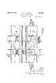
- FIG. l is aseotional plan of a transfer station .having through tracks for both thelongitudinal and transfer cranes, this view being broken away in two regions to show the two vend portions and the central portion of the'station;
- Fig. 2 is a sectional side elevation similarly broken away of the embodiment shown in Fig. 1;
- Fig. 3 is a sectional end view of this embodiment;
- Fig. 4 is a plan similar to'Fig. 1 but cordingly, this bridge may be located so that its two rails 102 align with the rails44 of the inbound aisleway, or so that these rails 102 align with the rails 24 of the outbound aisleway. This enables the traveling crane to be passed from either of these aisleway tracks onto the track 102 of the transfer bridge and shifted thereby laterally with its load.
- a loaded body arriving by the truck C may be lifted by a crane 7 0 on the trackway 44, deposited in a suitable location, unloaded through one of its end doorways'and its contents hand trucked to the delivery vehicle B.
- the crane 70 picks up such unloaded body and trolleys it lengthwise of the station untilthe crane 7 0 passes onto the bridge which at that time is located with its rails 102 aligning with the rails 44.
- the bridge may carry this crane with its body t0 the outbound aisle, whereupon the crane 70 acting in this aisle carries the body to any convenient location where it may be reloaded and afterwards deposited on the outbound truck B. In these movements the body being transferred may pass over other bodies as indicated in Fig. 5.
- the bridge 100 is preferably provided with Aa suitable electric motor gearing with the shaft of one pair of its supporting wheels,
- a loaded body received from truck C may be trolleyed lengthwise of the house over other bodies that may be standing in the aisle 40 and deposited in any available space for unloading. Or, if there is no such space at the time, the body may be carried by its crane 7 0 to the transfer region and then transferred by the bridge 100 or the crane 88 to a storage space on either platform, and later returned by reverse operation to a position for unloading.
- the empty body When unloaded in the aisle 40, the empty body may if desired be rolled by suitable hand trucks (or on wheels of its own, if such are employed) to the storage space, to be later progressed by similar means to the outbound aisle. Once in the outbound aisle, the body Vmay be there reloaded and then lifted by the crane 71 for depositing on the outgoing truck I).
- inbound platform on the outer side ofthe in'- hicle. runways on the'outer sides of the two Y platforms, a pair ⁇ of crane trackwaysabo-ve the respective aisleways and parallel therewith, a vehicle runway extending transversely beneath both crane trackways, an overhead transverse trackway extending across both aisle trackways, hoisting and raising means adapted to travel onan aisle'trackway, and a trolleying support adaptedto travel on the overhead transverse trackway, whereby a demountable body may be raised from a vehicle in the transverse runway, trolleyed lengthwise of the inbound aisleway, deposited and unloaded, thereafter trolleyed transversely to the outbound aisleway, reloaded and deposited on a vehicle in the transverse runway.
- a freight transfer station having a platformproviding a pair of parallel longitudinal aisleways with inbound and outbound package space on their outer sides respectively, crane trackways above the respective aisleways overhanging. a vehicle runway at the end of the platform, a traveling crane on each trackway, a transverse pent house above thetwo crane trackways, and a traveling crane in said pent house adapted to .raise a a body between the rails of either longitudinal for transferring freight adapted' tollift bodies from the trucks and deposit .them in an aisle or vice versa, the
- rails of the crane trackways being farther apart than the maximum length of the bodies, a crane trackway at a higher elevation than the trackways mentioned v and extending crosswise of them, and a traveling crane on aisle trackway entirely above the plane of bodiesl and the other for ⁇ the lastY mentioned cranetrackway adapted to raise a body between thejrails of keither that trackway and transport it toa position Z over the other aisle trackway and then lower it between the rails of that trackway.
- a-isleways each comprlsing a pair of rails spaced apart
- a traveling crane on one of the aisleway trackways adapted toV raise and transport a body lengthwise of the aisleway
- a trolleying l device on the transverse trackway adapted to carry a raised body y A from one aislewayto the other, the longitudinal and transverse trackways being at right angles'to each other and one of them having its rails spaced a slightly greater distance than the length of a body and the other having its rails spaced a slightly greater distance than the width of a body.
- An apparatus for transferring freight comprising a station provided 'with two longitudinal crane trackways, one for incoming outgoing bodies, ay transverse vehicle runway extending beneath both of said crane trackways, a lateral trackway, means adapted to be on the longitudinal t-rackways for raising bodies and trolleying them along such trackways, means on the lateral trackway for transferring a raised body from one longitudinal trackway to the other, platforms on the outer sides of the lanes'beneath the two crane trackways, and 56,;
Landscapes
- Engineering & Computer Science (AREA)
- Mechanical Engineering (AREA)
- Carriers, Traveling Bodies, And Overhead Traveling Cranes (AREA)
Description
March 29, 1932'. B. F. FITCHET AL SYSTEM OF HANDLING FREIGHTn Filed Sept. 27, 1929 PACKAGE.
DELIVERY 4 Sheets-Sheet zl-/Z OUTBOUND PACKAGE HECE/VlN Cltfomww/ March 29, 1932. B F, F|TC|| ET AL 1,851,539
SYSTEM OF HANDLING' FREIGHT Filed sept. 27, 1929 4 sheets-sheet 2 TE O March 29, 1932.
B. F; FITCH ET AL 1,851,539
SYSTEM OF HANDLING FREIGHT Filed Sept. 27, 1929 4 Sheets-Sheet 3 March 29, 1932. B. F. FITCH ET Al.
l SYSTEM 0F HANDLING FREIGHT,
Filed Sept. 27, 1929 4 Sheets-Sheet 4 l gru/wanton:
Vf'- @u QSI Q Patented Mar. 29, 1932 i UNITED STATES PATENT vori-ICE `BENJAMIN F. FITCH,v oF GREENwICi-I, CONNECTICUT, AND ALBERT R. TEARE, 0E LAKE- 'Y woon, 0R10', AssIGNoRs To MCTCR TERMINALS COMPANY, oF WILMINGTONDEEA- WARE, A- CORPORATION 0E DELAWARE SYSTEM 0F HANDLING FREIGHT Application filed September 27, 19,29. Serial No. 395,672.
This invention relates to a transfer station equipped and arranged for handling demountable automobile bodies for readilyrreceiving such bodieslo-aded,unloading package freight from such bodies and reloading package freightinto unloaded bodies, and
for the, dispatch of the reloaded bodies. The
station also provides for the convenient loading of the inbound packages into delivery carriers, and for the convenient receipt of freight from outbound carriers and its loading into the empty containers.
To the above end, we provide an inbound aisleway with a traveling crane adapted to remove loaded bodies fro-m trucks at the end ofthe aisleway, we provide a parallel outbound aisleway equipped with a traveling craneto enable the freshly loaded body to be mounted on the truckand we provide a transversely acting overhead support to'enable the lateral transfer o-f bodies from the inbound to the outbound aisleway or vice versa. Thus, for instance, bodies which have been deposited in the inbound aisleway and have just been emptied may be .transferred intof position in the outbound aisleway ready for reloading by package freight received on the outbound platform, and subsequently transferred to an automobile truck.
The two traveling cranes mentioned are each arranged to lift bodies for a greater distance above the platform than the height of a body, so that `one body may be trolleyedA over a. body standing on the platform. This enables received bodies to be `deposited in any vacant space in the inbound aisle, and, when empty, to be transferred to any vacant space in the outbound aisle for reloading, or bodies fer crane located in a pent house above-the path of travel of the aisle cranes and arranging the tracks of the aisle cranes so that there v 1s space enough between them for'the passage of a body to a position entirely above such tracks. Our second way in which weV propose to accomplish this result is to provide a lat-f eral crane trackway above the plane of the` aisle trackways and then interrupt these aisle trackways where the lateral trackway `passes over them andprovide on the lateral trackway a shiftable member, which has `crane tracks adapted to align with the interrupted aisle tracks. Accordingly, whensuch alignment is effected the crane of that aisle may be run onto the tracks of the transfer device and carried bodily with its load to the other aisle, when it may be run off of the transfer device onto the trackways o-f that aisle.
The aisles and traveling cranes are so arranged thatthe bodies are l*preferably trol-x leyed sidewise, and these bodies are provided with doors at opposite ends, so that in loading the package freight on the outbound platform, such freight may be transferred directly into the open Vend of thel body fromr one or more vehicles at the opposite edge of the platform, or from piles of packages tem. porarily deposited on the platform. Simi-'5 larly at the inbound aisleway, the freight is hand trucked through the open doors at the other endsof the bodies onto the inbound Y riers may not be available at the time the l body is received, the inbound platform is preferably made wider than the outbound, to provide more storage space. i
The drawings illustrate our invention with the two dierent embodiments of transferv mechanism above mentioned.` Fig. l is aseotional plan of a transfer station .having through tracks for both thelongitudinal and transfer cranes, this view being broken away in two regions to show the two vend portions and the central portion of the'station; Fig. 2 is a sectional side elevation similarly broken away of the embodiment shown in Fig. 1; Fig. 3 is a sectional end view of this embodiment; Fig. 4 is a plan similar to'Fig. 1 but cordingly, this bridge may be located so that its two rails 102 align with the rails44 of the inbound aisleway, or so that these rails 102 align with the rails 24 of the outbound aisleway. This enables the traveling crane to be passed from either of these aisleway tracks onto the track 102 of the transfer bridge and shifted thereby laterally with its load.
The embodiment shown in Figs. 5 and 6 and just described enables the bodies to be received, unloaded, transferred, reloaded and discharged in a system of operation similar to that described for the other embodiment. Thus, a loaded body arriving by the truck C may be lifted by a crane 7 0 on the trackway 44, deposited in a suitable location, unloaded through one of its end doorways'and its contents hand trucked to the delivery vehicle B. The crane 70 then picks up such unloaded body and trolleys it lengthwise of the station untilthe crane 7 0 passes onto the bridge which at that time is located with its rails 102 aligning with the rails 44. Then the bridge may carry this crane with its body t0 the outbound aisle, whereupon the crane 70 acting in this aisle carries the body to any convenient location where it may be reloaded and afterwards deposited on the outbound truck B. In these movements the body being transferred may pass over other bodies as indicated in Fig. 5.
The bridge 100 is preferably provided with Aa suitable electric motor gearing with the shaft of one pair of its supporting wheels,
' whereby it may be propelled along its trackway 90, as desired. I have indicated such motor at 105 geared with the shaft 106 of the wheels 107.
It will be seen that our apparatus provides for a very flexible operation according to traffic conditions existing at the time. A loaded body received from truck C may be trolleyed lengthwise of the house over other bodies that may be standing in the aisle 40 and deposited in any available space for unloading. Or, if there is no such space at the time, the body may be carried by its crane 7 0 to the transfer region and then transferred by the bridge 100 or the crane 88 to a storage space on either platform, and later returned by reverse operation to a position for unloading. When unloaded in the aisle 40, the empty body may if desired be rolled by suitable hand trucks (or on wheels of its own, if such are employed) to the storage space, to be later progressed by similar means to the outbound aisle. Once in the outbound aisle, the body Vmay be there reloaded and then lifted by the crane 71 for depositing on the outgoing truck I).
1. In a transfer station, the combination of a pair of vehicle aisleways one for incoming bodies, the other for outgoing bodies, an
inbound platform on the outer side ofthe in'- hicle. runways on the'outer sides of the two Y platforms, a pair `of crane trackwaysabo-ve the respective aisleways and parallel therewith, a vehicle runway extending transversely beneath both crane trackways, an overhead transverse trackway extending across both aisle trackways, hoisting and raising means adapted to travel onan aisle'trackway, and a trolleying support adaptedto travel on the overhead transverse trackway, whereby a demountable body may be raised from a vehicle in the transverse runway, trolleyed lengthwise of the inbound aisleway, deposited and unloaded, thereafter trolleyed transversely to the outbound aisleway, reloaded and deposited on a vehicle in the transverse runway.
2. In a transfer station,` the combination of inbound and outbound aisleways with platforms on their outer sides, vehicle runways on the outer sides of said platforms, longitudinal crane trackways supported overhead Vabove such aisleways respectively, a transverse vehicle runway overhung by such crane trackways, a transverse trackway at a higher level than the longitudinal trackways and extending uninterruptedly from one aisle region to theother, a transversely movable supporting device on. the transverse vtrackway adapted to support a suspendedbody, and a traveling crane on one ofthe aisle trackways adapted to supporta suspended body and pass beneath the transverse trackways. V-
3. A freight transfer station having a platformproviding a pair of parallel longitudinal aisleways with inbound and outbound package space on their outer sides respectively, crane trackways above the respective aisleways overhanging. a vehicle runway at the end of the platform, a traveling crane on each trackway, a transverse pent house above thetwo crane trackways, and a traveling crane in said pent house adapted to .raise a a body between the rails of either longitudinal for transferring freight adapted' tollift bodies from the trucks and deposit .them in an aisle or vice versa, the
rails of the crane trackways being farther apart than the maximum length of the bodies, a crane trackway at a higher elevation than the trackways mentioned v and extending crosswise of them, and a traveling crane on aisle trackway entirely above the plane of bodiesl and the other for` the lastY mentioned cranetrackway adapted to raise a body between thejrails of keither that trackway and transport it toa position Z over the other aisle trackway and then lower it between the rails of that trackway.
5. In a transfer station, the combination of a platform providing a pair of parallel aisleways one for incoming bodies and theY ,other for outgoing bodies, crane trackways above. the respective. a-isleways each comprlsing a pair of rails spaced apart, a transverse trackway'comprising a ypair yof rails spaced apart, a traveling crane on one of the aisleway trackways adapted toV raise and transport a body lengthwise of the aisleway, and a trolleying l device on the transverse trackway adapted to carry a raised body y A from one aislewayto the other, the longitudinal and transverse trackways being at right angles'to each other and one of them having its rails spaced a slightly greater distance than the length of a body and the other having its rails spaced a slightly greater distance than the width of a body.
6; The combination of trucks having demountableV bodies materially longer than they are wide, a freight transfer station having a pairof parallel longitudinal aisleways i for inbound and outbound'bodies respectively,crane traclways above the respective aisleways each comprising a pair of rails spaced apart a greater distance than the length of said demountable bodies, atraveling crane on each trackway, a transverse crane trackway above the trackways first mentioned, and a crane on the transverse trackway adapted to raise one of said demountable bodies between the rails of either longitudinal trackway and entirely above the plane ofeach trackway.
7. An apparatus for transferring freight comprising a station provided 'with two longitudinal crane trackways, one for incoming outgoing bodies, ay transverse vehicle runway extending beneath both of said crane trackways, a lateral trackway, means adapted to be on the longitudinal t-rackways for raising bodies and trolleying them along such trackways, means on the lateral trackway for transferring a raised body from one longitudinal trackway to the other, platforms on the outer sides of the lanes'beneath the two crane trackways, and 56,;
vehicle runways on the outer sides of the two platforms.
In testimony whereof, we hereunto affixV our signatures.
v BENJAMIN F. FITCH. ALBERT R. TEARE.
Priority Applications (1)
| Application Number | Priority Date | Filing Date | Title |
|---|---|---|---|
| US395672A US1851539A (en) | 1929-09-27 | 1929-09-27 | System of handling freight |
Applications Claiming Priority (1)
| Application Number | Priority Date | Filing Date | Title |
|---|---|---|---|
| US395672A US1851539A (en) | 1929-09-27 | 1929-09-27 | System of handling freight |
Publications (1)
| Publication Number | Publication Date |
|---|---|
| US1851539A true US1851539A (en) | 1932-03-29 |
Family
ID=23564009
Family Applications (1)
| Application Number | Title | Priority Date | Filing Date |
|---|---|---|---|
| US395672A Expired - Lifetime US1851539A (en) | 1929-09-27 | 1929-09-27 | System of handling freight |
Country Status (1)
| Country | Link |
|---|---|
| US (1) | US1851539A (en) |
Cited By (8)
| Publication number | Priority date | Publication date | Assignee | Title |
|---|---|---|---|---|
| US2670859A (en) * | 1949-07-01 | 1954-03-02 | Webb & Knapp Inc | Automobile parking system |
| US2726774A (en) * | 1948-11-08 | 1955-12-13 | Rosenbaum Q B Kl Parking Co | Machine for parking motor vehicles |
| US20050053451A1 (en) * | 1999-02-11 | 2005-03-10 | Pierre Gagnon | Vehicle loading and unloading system |
| CN104229370A (en) * | 2014-09-26 | 2014-12-24 | 昆明七零五所科技发展总公司 | Positioning device and positioning method for rail guide vehicle with steering function |
| CN104619619A (en) * | 2012-09-10 | 2015-05-13 | 应用材料公司 | Substrate transfer device and method for moving substrate |
| CN104648879A (en) * | 2015-01-23 | 2015-05-27 | 徐州德坤电气科技有限公司 | Digital-bus-based intelligent logistics carrying transportation unit |
| US10442446B2 (en) | 2016-05-20 | 2019-10-15 | Standart Car Truck Company | Auto-rack railroad car bridge plate and bridge plate locking assembly |
| US11273850B2 (en) | 2019-06-04 | 2022-03-15 | Standard Car Truck Company | Auto-rack railroad car bridge plate and bridge plate locking assembly |
-
1929
- 1929-09-27 US US395672A patent/US1851539A/en not_active Expired - Lifetime
Cited By (10)
| Publication number | Priority date | Publication date | Assignee | Title |
|---|---|---|---|---|
| US2726774A (en) * | 1948-11-08 | 1955-12-13 | Rosenbaum Q B Kl Parking Co | Machine for parking motor vehicles |
| US2670859A (en) * | 1949-07-01 | 1954-03-02 | Webb & Knapp Inc | Automobile parking system |
| US20050053451A1 (en) * | 1999-02-11 | 2005-03-10 | Pierre Gagnon | Vehicle loading and unloading system |
| CN104619619A (en) * | 2012-09-10 | 2015-05-13 | 应用材料公司 | Substrate transfer device and method for moving substrate |
| CN104619619B (en) * | 2012-09-10 | 2017-08-11 | 应用材料公司 | Substrate transfer device and method for moving substrate |
| CN104229370A (en) * | 2014-09-26 | 2014-12-24 | 昆明七零五所科技发展总公司 | Positioning device and positioning method for rail guide vehicle with steering function |
| CN104648879A (en) * | 2015-01-23 | 2015-05-27 | 徐州德坤电气科技有限公司 | Digital-bus-based intelligent logistics carrying transportation unit |
| CN104648879B (en) * | 2015-01-23 | 2018-06-08 | 徐州德坤电气科技有限公司 | A kind of Intelligent logistics support based on number bus carries delivery unit |
| US10442446B2 (en) | 2016-05-20 | 2019-10-15 | Standart Car Truck Company | Auto-rack railroad car bridge plate and bridge plate locking assembly |
| US11273850B2 (en) | 2019-06-04 | 2022-03-15 | Standard Car Truck Company | Auto-rack railroad car bridge plate and bridge plate locking assembly |
Similar Documents
| Publication | Publication Date | Title |
|---|---|---|
| US1522707A (en) | Freight-handling system | |
| TWI601679B (en) | Method for loading and unloading containers of container warehouses and container-transportation facilities | |
| EP0133472B1 (en) | Vertical stacking terminal for containers | |
| US3583584A (en) | Warehousing | |
| NL8200975A (en) | TRANSPORTATION DEVICE FOR A STORAGE INSTALLATION. | |
| JPH10504507A (en) | Cargo transfer method and equipment | |
| US1851539A (en) | System of handling freight | |
| US2447559A (en) | System for transferring package freight | |
| US3568862A (en) | Air freight installation with article handling and storage means | |
| US10611288B2 (en) | Transport vehicle for containers | |
| JP2020529352A (en) | Vehicle body immersion plant | |
| US1828308A (en) | Apparatus for handling and storing automobiles and the like | |
| US1577184A (en) | Freight-transferring system | |
| US2107292A (en) | Freight handling apparatus | |
| US1275145A (en) | Transfer system for freight-terminals. | |
| US1785168A (en) | Loading and unloading apparatus | |
| US1437968A (en) | Freight-transferring apparatus | |
| US1261504A (en) | Freight-transfer station and warehouse. | |
| JPS6031445A (en) | Load conveyer equipment using pallet | |
| JP2000264406A (en) | Automatic warehouse with bridging function | |
| US20240132286A1 (en) | Container terminal | |
| US11845481B2 (en) | Rail and train system | |
| US2444297A (en) | Transport vehicle and interchangeable freight container | |
| US1303359A (en) | moore | |
| KR100759035B1 (en) | Container Logistics Processing Method |