US1851513A - Aircraft and watercraft construction - Google Patents
Aircraft and watercraft construction Download PDFInfo
- Publication number
- US1851513A US1851513A US377416A US37741629A US1851513A US 1851513 A US1851513 A US 1851513A US 377416 A US377416 A US 377416A US 37741629 A US37741629 A US 37741629A US 1851513 A US1851513 A US 1851513A
- Authority
- US
- United States
- Prior art keywords
- propeller
- blades
- medium
- aircraft
- turbine
- Prior art date
- Legal status (The legal status is an assumption and is not a legal conclusion. Google has not performed a legal analysis and makes no representation as to the accuracy of the status listed.)
- Expired - Lifetime
Links
- 238000010276 construction Methods 0.000 title description 10
- 239000003570 air Substances 0.000 description 11
- XLYOFNOQVPJJNP-UHFFFAOYSA-N water Substances O XLYOFNOQVPJJNP-UHFFFAOYSA-N 0.000 description 11
- 239000012530 fluid Substances 0.000 description 7
- 230000008901 benefit Effects 0.000 description 5
- 238000002474 experimental method Methods 0.000 description 5
- 239000007789 gas Substances 0.000 description 4
- 230000006835 compression Effects 0.000 description 2
- 238000007906 compression Methods 0.000 description 2
- 230000004048 modification Effects 0.000 description 2
- 238000012986 modification Methods 0.000 description 2
- 230000007935 neutral effect Effects 0.000 description 2
- 239000000779 smoke Substances 0.000 description 2
- 101100001674 Emericella variicolor andI gene Proteins 0.000 description 1
- 238000001816 cooling Methods 0.000 description 1
- 238000005520 cutting process Methods 0.000 description 1
- 238000007599 discharging Methods 0.000 description 1
- 210000003746 feather Anatomy 0.000 description 1
- 238000004519 manufacturing process Methods 0.000 description 1
- 239000002609 medium Substances 0.000 description 1
- 229920000136 polysorbate Polymers 0.000 description 1
- 238000003825 pressing Methods 0.000 description 1
- 238000005096 rolling process Methods 0.000 description 1
- 238000009423 ventilation Methods 0.000 description 1
Images


Classifications
-
- B—PERFORMING OPERATIONS; TRANSPORTING
- B64—AIRCRAFT; AVIATION; COSMONAUTICS
- B64C—AEROPLANES; HELICOPTERS
- B64C11/00—Propellers, e.g. of ducted type; Features common to propellers and rotors for rotorcraft
-
- Y—GENERAL TAGGING OF NEW TECHNOLOGICAL DEVELOPMENTS; GENERAL TAGGING OF CROSS-SECTIONAL TECHNOLOGIES SPANNING OVER SEVERAL SECTIONS OF THE IPC; TECHNICAL SUBJECTS COVERED BY FORMER USPC CROSS-REFERENCE ART COLLECTIONS [XRACs] AND DIGESTS
- Y10—TECHNICAL SUBJECTS COVERED BY FORMER USPC
- Y10S—TECHNICAL SUBJECTS COVERED BY FORMER USPC CROSS-REFERENCE ART COLLECTIONS [XRACs] AND DIGESTS
- Y10S415/00—Rotary kinetic fluid motors or pumps
- Y10S415/914—Device to control boundary layer
Definitions
- My invention relates to a propeller for operation in a fluid medium that may be air, water or gas, the propeller being thought to have its widest application upon aircraft and watercraft, and the invention being in part a development of the subject matter of my earlier application Ser. No. 353,407 entitled Propeller or turbine for water, air and gases, filed April 8, 1929.
- a purpose of my invention is to provide a novel propeller structure that will be easy and inexpensive to manufacture and which will well meet the needs of service.
- a further purpose is to provide a propeller 16 that will deliver a suitable quantity of the fluid upon which it is operating to the front of the propeller blade, lessening suction im-' mediately in front of the propeller by returning forward a portion of the fluid medium thzlzlt is being thrown rearward by the prope er.
- a further purpose is to mount a propeller blade upon the outside circumference of a hollow shell delivering a portion of the propeller discharge into the interior of the shell and thence forwardly to the receiving side of the propeller.
- a further purpose is to provide a propeller member with outer vanes that direct the fluid medium rearwardly and inner vanes that return forwardly a small portion of the medium that has already been acted upon by the outer blades.
- a further purpose is to mount propeller blades upon a two-part hollow body, roviding an opening between the parts t rough which opening part of the discharging medium can enter inside the body to be released later through openings toward the front of the body.
- a further purpose is to mount a dynamo upon a propeller shaft adjacent a propeller.
- a further purpose is to hinge propeller blades around the outside circumference of a streamline body.
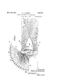
- Figure l is a view illustrating the results of an experiment made with the new propeller, the view being a side elevation of structure embodying one form'of my invention and showing streamlines as found by experiment in the medium acted upon by the propeller.
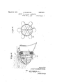
- Figures 2 and 3 are respectively front elevation and sectional side elevation of propeller structure embodying a form of my invention that is well adapted to use in water.
- Figure 4 is a fragmentary partially sec- 66 tional longitudinal view showing somewhat difi'ferent form of propeller for use with aircra t.
- Figure 5 is a front elevation of the propeller shown in Figure 4.
- Figures 6 and 7 are sections respectively upon the lines 6-6 and 7-7 of Figures 7 and 6 and show mounted upon a boat another form of propeller structure that embodies my invention.
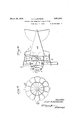
- Figures 8 and 9 are front and side elevations respectively of another embodiment of my invention for use as a wind motor, Figure 8 showing propellers only.
- Figures 10 and. 11 are front and side elevations respectively of another form illus'trat-. ing a minor modification from that of Figures 2 and 3.
- Figures 12, 13 and 14 are respectively rear end elevation, top plan and side elevation of a streamline body propeller for aircraft.
- the smoke-candles M were arranged along the circle line R in front of the propeller and the lines of smoke T from the candles were in approximate accord with the figure and show clearly the reaction of the medium in which thepropeller or'turbine is rotating.
- the experiment shows how the medium is drawn to the propeller blades passing in be- 109 tween them under high pressure and thrown backwards with very high speed in the form of a compressed medium column.
- a propeller or turbine with a streamline body gives a minimum of resistance to motion forward.
- the front part al opens the way through the medium and the rearwardly tapering rear part all is pressed forward when the compressed medium column 0 back of the propeller blades expands towards the propeller center.
- The" medium mass is drawn inward to the propeller with great force, at the same time being pressed by the tapering front part al of the body to the propeller blades 6, thus giving these blades a highly compressed medium in which to work.
- the propeller or turbine blades will cut into this compressed medium, similarly to a bolt in a nut.
- the propeller or turbine blades a draw (through a great vacuum) the medium to the propeller from a spherical space in front of and sideward of the blades represented in Figure '1 by the sphere R and the conical bottom of the rearmost smoke lines T, back of which an inactively rolling medium Q around I pressure driving the streamline body forward like a piston.
- Figure 1 also shows an opening it between the frontpart al and the rear part all of the streamline body, through which opening a part of the medium mass is diverted to the inside of the streamline body.
- the sharp edge X and the concave stream line-formed hollows U of all direct part of the medium inward and forward to the hollow front part al, from where this medium is side to the front part of al and pressing it v out through the openings V.
- Vents inside al can be used to drive this additional medium forward as well by forward as rearward motion of the craft driven by the propeller.
- Figures 2 and .3 show a streamline body propeller for water, consisting of three parts :-the front part al, the propeller ring p with the inside ventilator blades r and outside propeller blades 6, and finally the rear part all with its cutting edge X and streamline formed concave hollowsZ to lead part of the medium inwardly and forwardly.
- the radial blades 7) on the front part al serve the purpose of drawing the medium to al and then throwing it out at the ends 3 of the blades, whereby it is mixed with the medium' coming from the interior of the streamline body that is being driven forward by the blades 1- and the combined flows are driven out to the propeller blades e.
- the rear edge of the propeller ring is curved inwardly in order to facilitate the entry of a part of the medium into the opening it between the propeller ring 12 and the rear part all.
- Figures 4 and 5 show an aircraft streamline propeller consisting of the front part and the inner and outer turbine propellers all and cl which'pitch and therefore drive in opposite directions.
- the inner turbine blades ell are constructed as spokes of the whole duplex turbine propeller.
- This arrangement can be used also for propellers in water. When falling down, naturally the blades must not touch the engine or other parts.
- the front part is a streamline combination of several segment rings, arranged one after another on the propeller, which rings because of their special profiles draw the air or other fluid medium to the front part and then force the medium out through the openings as additional medium for the outside propeller blades.
- FIG. 6 and 7 show again a'boat propeller in three parts, so constructed that here the front part aI serves as a shaft bearing C and therefore is not rotating.
- the front part (11 ) carries the curved ventilator blades '01, so arranged as to collect the medium, water, air or the like by forward motion of the vessel and deliver it without losses in compressed form (or, in the case of water, at high velocity) to the propeller blades e.
- the ventilator blades '01 are curved in a direction opposite to the rotating direction of the propeller or turbine blades e and there-- fore the medium coming from 121 will meet the blades 6 tangentially.
- Figures 8 and 9 show a streamline wind motor or turbine which is directly connected to the shaft of a dynamo for the purpose of generating electric current and this wind motor or turbine can be placed directly on a mast, antenna or on an airplane or airship or on other crafts in each case so arranged as to be movable to continually face the wind.
- the compression funnel '7 serves the purpose of giving the medium (air, water or gas) entering between the funnelf and the front part aI, compression and higher speed before reaching the propeller or turbine blades 61.
- the funnel-spokes r, placed within the funnel in front of the blades eI are curved and given a pitch to make the passing medium column rotate in the desired direction.
- Another advantage of the medium current passing through (11 is the resultant excellent cooling of the dynamo 70.
- the wind motor can be used 'to drive an air, gas .or water pump or the like, which in case of need may be placed inside the rear part aII.
- the propeller having a great arcuate ex high density.
- Figures 12, 13 and 14 show a streamline propeller of simple construction that is especially suitable for aircraft or the like because of its great simplicity and sturdiness.
- the propeller consists of the front part (11 and the propeller blades el and 011.
- the two inside blades 6H are fastened to i the central hub n and the two outside blades are fastened to the carrying plates P located' at the ends of the inside blades.
- I I 4 The'inside and outside blades have opposite driving direction or pitch and the outside blades ell can be fastened to the plates P by means of a suitable hinge, so as to fall back into a neutral position when the craft glides with the engine ofi'.
- the front part (11 is in this case a conical wind shield, carrying on its front surface two or more ventilator blades r.
- ventilator blades can be curved, as in Figure 6, in which case during gliding flight the wind pressure will keep the whole propeller and the engine in a slow rotation, thus making it possible to start the engine at will even with the-outside propeller blades in neutral position.
- the front part all can also be left out without aloss of the overfeeding of the outside propeller blades with medium, because the 'insideblades will continue their function just the same.
- the body back of the propeller blades should be streamline shaped as for instance an airplane body.
- pro grannnatic and the illustrated type of hinge connection 63 between the driving portion of the propeller and the inner portion thereof is intended as a conventional showing for any hinge adapted to function in the intended wav.
- a body In a propeller of the character indicated, a body, one or more propeller blades around the outside circumference thereof and deflecting'surfaces directing a portion of the discharge from the propeller from the discharge side of the propeller to a point on the intake side of the propeller.
- apropeller of the character inclicated. a streamline body, one or more propeller blades around the outside circumference thereof and deflecting surfaces directing a portion of the discharge from the propeller into the interior of the body for redelivery on the intake side of the propeller.
- outer blades adapted to direct the fluid medium rearwardly and inner blades adapted to direct a portion of the discharge from the outer blades forwardly and delivering it on the intake side.
- propeller In a propeller of the character indicated. a hollow streamline body, propeller.
- a hollow streamline body having forward and rearward openings into its interior and an outside propeller blade between the openings adapted to deliver a portion. of its discharge into the hollow through the rearward openings to be thrown out at right angles to the driving direction through the forward openings.
- a hollow streamline body consisting of three parts, front part, intermediate part and rear part, the intermediate part including a propeller ring and inside and outside blades mounted thereon, the rear part being provided with a forwardly directed concave hollow adapted to receive discharge from the outside blades and the forward part having a rearwardly communicating hollow adapt-ed to receive the medium from the rearward part and to deliver it through openings to the I outside of the body in front of the outside blades.
- a propeller for an aircraft having a hollow streamline body, turbine blades on an intermediate part thereof outside of the body, and other blades on the inside of the body constructed as spokes thereof.
- a hollow streamline body having a succession of segment rings at the forward end thereof, propeller blades ranged around the outside end of the body rearward of the rings and adapted to deliver part of its discharge into the interior ,of the body rearward of the, blades for return through the opening between the rings to the receiving side of the propeller.
- a funnel member mounted to shift its direction with the wind, a three part streamline body spaced inwardly from the inside. of the funnel having a for-. ward part and rearward part rigidly connected to the funnel by blades arranged as spokes and an intermediate part mounted to rotate with respect to the front and rear parts which rotatably support the intermediate part, and blades mounted upon the intermediate part extending outwardly toward the interior of the funnel.
- a three part'streamline body a funnel member surrounding the bodycoaxially and rigidly supporting the front and rear parts of the body and itself adapted to shift with the wind, the intermediate part being rotatably mounted upon one or both of the other parts and carrying pro- I peller blades inside the funnel, and rearward part being hollowed and open rearwardly of the blades to receive a portion of the discharge therefrom for return throu h the intermediate part and through the forward part for deliver to the receiving side of the blades.
- a ropeller having oppositely extending bla es pitched to direct the air forwardly near the hub and to direct the air rearwardly toward the outer ends of the blades.
- a propeller havin oppositely extending blades pitched to irect the air forwardl near the hub and to direct the air fearwar y toward the outer ends of the blades, in combination with a hinge connection between the outer and inner portions of the blades adapting the outer portions of the blades to feather when pressed upon the 80 forward side. 7
- a propeller shaft In an aircraft, a propeller shaft, a comcal wind shield-upon the forward end thereof, propeller'blades on the shaft rearwardly of the shield and vanes on the shield to guide the air to the outer portion of the propeller blades.
Landscapes
- Engineering & Computer Science (AREA)
- Aviation & Aerospace Engineering (AREA)
- Structures Of Non-Positive Displacement Pumps (AREA)
Description
March 29, 1932 A. HOLMSTROM AIRCRAFT AND WATERCRAFT CONS TRUCTION ts-Sheet 1 Filed July 11, 1929 March 29, 1932. HOLMSTROM AIRCRAFT AND WATERCRAFT CONSTRUCTION Filed July 11, 1929 6 Sheets-Sheet 2 March 29, 1932. A. HOLMSTROM 1,851,513
AIRCRAFT AND WATERCRAFT CONSTRUCTION Filed July 11, 1929 6 Sheets-Shet 3 March 29, 1932. A. HOLMSTROM 1,851,513
I AIRCRAFT AND WATERCRAFT CONSTRUCTION I Filed July 11, 1929 6 Sheets-Sheet 4 March 29, 1932.- A. HOLMSTROM AIRCRAFT AND WATERCRAFT CONSTRUCTION Filed July 11, 1929 6 Sheets-Shem; 5
Inventor uxe Z HOZm-SIFOJZZ,
March 29, 19322. I A. HOLMSTROM 1,851,513
AIRCRAFT AND WATERCRAFT CONSTRUCTION Filed July 11, 1929 6 Sheets-Sheet 6 [7w enlar fixel Jfalzmstrom,
P uQmil/gy Patented Mar. 29, 1932 UNITED STATES AXEL HOLMSTB-OM, OF MONTE CARLO, MONACO AIRCRAFT AND WATERCRAFT CONSTRUCTION Application filed July 11, 1929, Serial No.
My invention relates to a propeller for operation in a fluid medium that may be air, water or gas, the propeller being thought to have its widest application upon aircraft and watercraft, and the invention being in part a development of the subject matter of my earlier application Ser. No. 353,407 entitled Propeller or turbine for water, air and gases, filed April 8, 1929.
A purpose of my invention is to provide a novel propeller structure that will be easy and inexpensive to manufacture and which will well meet the needs of service.
A further purpose is to provide a propeller 16 that will deliver a suitable quantity of the fluid upon which it is operating to the front of the propeller blade, lessening suction im-' mediately in front of the propeller by returning forward a portion of the fluid medium thzlzlt is being thrown rearward by the prope er. V v
A further purpose is to mount a propeller blade upon the outside circumference of a hollow shell delivering a portion of the propeller discharge into the interior of the shell and thence forwardly to the receiving side of the propeller.
A further purpose is to provide a propeller member with outer vanes that direct the fluid medium rearwardly and inner vanes that return forwardly a small portion of the medium that has already been acted upon by the outer blades.
A further purpose is to mount propeller blades upon a two-part hollow body, roviding an opening between the parts t rough which opening part of the discharging medium can enter inside the body to be released later through openings toward the front of the body. I
A further purpose is to mount a dynamo upon a propeller shaft adjacent a propeller.
A further purpose is to hinge propeller blades around the outside circumference of a streamline body.
Further purposes will appear in the specification and in the claims.
I have elected to show a few only of the different forms of my invention, illustrating these to considerable extent diagrammati- 377,416, and in Germany May 17, 1929.
cally and selecting forms that are practical and efficient in operation and which well illu strate the principles involved.
Figure l is a view illustrating the results of an experiment made with the new propeller, the view being a side elevation of structure embodying one form'of my invention and showing streamlines as found by experiment in the medium acted upon by the propeller.
Figures 2 and 3 are respectively front elevation and sectional side elevation of propeller structure embodying a form of my invention that is well adapted to use in water.
Figure 4 is a fragmentary partially sec- 66 tional longitudinal view showing somewhat difi'ferent form of propeller for use with aircra t.
Figure 5 is a front elevation of the propeller shown in Figure 4. r
Figures 6 and 7 are sections respectively upon the lines 6-6 and 7-7 of Figures 7 and 6 and show mounted upon a boat another form of propeller structure that embodies my invention. Y
Figures 8 and 9 are front and side elevations respectively of another embodiment of my invention for use as a wind motor, Figure 8 showing propellers only.
Figures 10 and. 11 are front and side elevations respectively of another form illus'trat-. ing a minor modification from that of Figures 2 and 3.
Figures 12, 13 and 14 are respectively rear end elevation, top plan and side elevation of a streamline body propeller for aircraft.
Describing in illustration and not inlimitation and referring to the drawings An experiment made by the inventor and shown in igure 1 gives a clear conception of how a propeller or turbine having a streamline body functions.
The smoke-candles M were arranged along the circle line R in front of the propeller and the lines of smoke T from the candles were in approximate accord with the figure and show clearly the reaction of the medium in which thepropeller or'turbine is rotating.
The experiment shows how the medium is drawn to the propeller blades passing in be- 109 tween them under high pressure and thrown backwards with very high speed in the form of a compressed medium column.
This type of propeller or turbine is altogether different from propellers or turbines now in use and has the following advantages:
A propeller or turbine with a streamline body gives a minimum of resistance to motion forward.
The front part al opens the way through the medium and the rearwardly tapering rear part all is pressed forward when the compressed medium column 0 back of the propeller blades expands towards the propeller center.
This minimum resistance is possible only with the type of propeller or turbine to which this invention refers, in which the propeller or turbine is provided-with a streamline body of unusually large diameter, a diameter over one third of the total outside propeller diameter.
The" medium mass is drawn inward to the propeller with great force, at the same time being pressed by the tapering front part al of the body to the propeller blades 6, thus giving these blades a highly compressed medium in which to work. The propeller or turbine blades will cut into this compressed medium, similarly to a bolt in a nut.
The propeller or turbine blades a draw (through a great vacuum) the medium to the propeller from a spherical space in front of and sideward of the blades represented in Figure '1 by the sphere R and the conical bottom of the rearmost smoke lines T, back of which an inactively rolling medium Q around I pressure driving the streamline body forward like a piston.
The experiments by the inventor showed an actual decrease of the diameter of the compressed medium column 0 back of the propeller blades (as illustrated in Figure 1)- which is of the greatest advantage for the expansionpressure towards the center.
Figure 1 also shows an opening it between the frontpart al and the rear part all of the streamline body, through which opening a part of the medium mass is diverted to the inside of the streamline body.
The sharp edge X and the concave stream line-formed hollows U of all direct part of the medium inward and forward to the hollow front part al, from where this medium is side to the front part of al and pressing it v out through the openings V.
Other optional ventilation blades inside al can be used to drive this additional medium forward as well by forward as rearward motion of the craft driven by the propeller.
That this new arrangement of feeding the propeller or turbine blades with additional medium from the inside of the propeller or turbine body is impossible with the present day propeller or turbine is evident.
The hubs to which the blades were fastened, were always too small for such'an arrangement and furthermore they never were of a hollow construction. Therefore the hollow propeller streamline bodies or hollow propeller hubs of any size as in the turbine streamline body propellers described below and illustrated in the Figures 2 to 9 are something absolutely new.
Figures 2 and .3 show a streamline body propeller for water, consisting of three parts :-the front part al, the propeller ring p with the inside ventilator blades r and outside propeller blades 6, and finally the rear part all with its cutting edge X and streamline formed concave hollowsZ to lead part of the medium inwardly and forwardly.
The radial blades 7) on the front part al serve the purpose of drawing the medium to al and then throwing it out at the ends 3 of the blades, whereby it is mixed with the medium' coming from the interior of the streamline body that is being driven forward by the blades 1- and the combined flows are driven out to the propeller blades e.
The rear edge of the propeller ring is curved inwardly in order to facilitate the entry of a part of the medium into the opening it between the propeller ring 12 and the rear part all.
Figures 4 and 5 show an aircraft streamline propeller consisting of the front part and the inner and outer turbine propellers all and cl which'pitch and therefore drive in opposite directions. The inner turbine blades ell are constructed as spokes of the whole duplex turbine propeller.
Something absolutely new is the arrangement of fastening the outside blades cl to the inside turbine with hinges. so that when the aircraft is gliding with the engine at rest they can automatically fall behind the nearest edge of the front part, thus eliminating the great friction and resistance of the usual stiff propellers during gliding.
As soon as the engine is started the centrifugal force brings the blades back to their active driving position.
This arrangement can be used also for propellers in water. When falling down, naturally the blades must not touch the engine or other parts.
The front part is a streamline combination of several segment rings, arranged one after another on the propeller, which rings because of their special profiles draw the air or other fluid medium to the front part and then force the medium out through the openings as additional medium for the outside propeller blades.
This will also cause good cooling-of the engine and associated mechanism.
The rear part of the streamline body is in this case the aircraft body itself which can taper rearwards conically or wedge-like. Figures 6 and 7 show again a'boat propeller in three parts, so constructed that here the front part aI serves as a shaft bearing C and therefore is not rotating.
The front part (11 carries the curved ventilator blades '01, so arranged as to collect the medium, water, air or the like by forward motion of the vessel and deliver it without losses in compressed form (or, in the case of water, at high velocity) to the propeller blades e.
The ventilator blades '01 are curved in a direction opposite to the rotating direction of the propeller or turbine blades e and there-- fore the medium coming from 121 will meet the blades 6 tangentially.
Figures 8 and 9 show a streamline wind motor or turbine which is directly connected to the shaft of a dynamo for the purpose of generating electric current and this wind motor or turbine can be placed directly on a mast, antenna or on an airplane or airship or on other crafts in each case so arranged as to be movable to continually face the wind.
The compression funnel '7 serves the purpose of giving the medium (air, water or gas) entering between the funnelf and the front part aI, compression and higher speed before reaching the propeller or turbine blades 61. The funnel-spokes r, placed within the funnel in front of the blades eI are curved and given a pitch to make the passing medium column rotate in the desired direction.
Through this arrangement these wind motors are given a maximum of speed and energy, especially as additional medium is taken through the opening u between the propeller turbine 01, eII and the tapering conical or wedge-shaped rear part aII and with great force driven forward to (11 by the inside turbine blades eII to escape through the rearwardly directed openings 42 and finally reach the blades 61. v I
Another advantage of the medium current passing through (11 is the resultant excellent cooling of the dynamo 70.
Instead of driving a dynamo, the wind motor can be used 'to drive an air, gas .or water pump or the like, which in case of need may be placed inside the rear part aII.
InFigures 10 and 11 I show a form of propeller in which the propeller blade winds around the full circumference of the body.
Obviously the arcuate extent of the individual propeller blades is a matter of design, being variant according to the speed at which the propeller is driven and also with the density of the fluid medium in which the propeller is operated.
The propeller having a great arcuate ex high density.
Figures 12, 13 and 14 show a streamline propeller of simple construction that is especially suitable for aircraft or the like because of its great simplicity and sturdiness.
-The propeller consists of the front part (11 and the propeller blades el and 011.
The two inside blades 6H are fastened to i the central hub n and the two outside blades are fastened to the carrying plates P located' at the ends of the inside blades. I I 4 The'inside and outside blades have opposite driving direction or pitch and the outside blades ell can be fastened to the plates P by means of a suitable hinge, so as to fall back into a neutral position when the craft glides with the engine ofi'.
The front part (11 is in this case a conical wind shield, carrying on its front surface two or more ventilator blades r.
These ventilator blades can be curved, as in Figure 6, in which case during gliding flight the wind pressure will keep the whole propeller and the engine in a slow rotation, thus making it possible to start the engine at will even with the-outside propeller blades in neutral position.
The front part all can also be left out without aloss of the overfeeding of the outside propeller blades with medium, because the 'insideblades will continue their function just the same. The body back of the propeller blades should be streamline shaped as for instance an airplane body.
It will be understood that while the pro grannnatic and the illustrated type of hinge connection 63 between the driving portion of the propeller and the inner portion thereof is intended as a conventional showing for any hinge adapted to function in the intended wav.
' The closed or feathered positions of the outer blades are shown in dot-and-dash lines at e5.
The four ventilator vanes shown in Figure 12 on the wind shield have been omitted in Figure 13 while Figure 14 shows two an omits two of these vanes.
In order to secure full advantage of my application already filed in Germany the description in this application has been conformed closely to that of the German case.
In view of my invention and disclosure variations and modifications to meet individual whim or particular need will doubtless become evident to others skilled in the art,'to obtain all or part of the benefits of my invention without copying the structure shown, andI. therefore, claim all such in so far as they fall within the reasonable spirit and scope of my invention.
Haviug'thus described my invention, what I claim as new and desire to secure by Letters Patent is:
1. In a propeller of the character indicated, a body, one or more propeller blades around the outside circumference thereof and deflecting'surfaces directing a portion of the discharge from the propeller from the discharge side of the propeller to a point on the intake side of the propeller.
2. In apropeller of the character inclicated. a streamline body, one or more propeller blades around the outside circumference thereof and deflecting surfaces directing a portion of the discharge from the propeller into the interior of the body for redelivery on the intake side of the propeller.
3. In a propeller of the character indicated,
.outer blades adapted to direct the fluid medium rearwardly and inner blades adapted to direct a portion of the discharge from the outer blades forwardly and delivering it on the intake side.
4. In a propeller of the character indicated. a hollow streamline body, propeller.
charging the medium that enters the rearthe outer blades.
- 6. In a propeller or turbine for water, a hollow streamline body having forward and rearward openings into its interior and an outside propeller blade between the openings adapted to deliver a portion. of its discharge into the hollow through the rearward openings to be thrown out at right angles to the driving direction through the forward openings.
7 In a propeller or turbine for water, a hollow streamline body consisting of three parts, front part, intermediate part and rear part, the intermediate part including a propeller ring and inside and outside blades mounted thereon, the rear part being provided with a forwardly directed concave hollow adapted to receive discharge from the outside blades and the forward part having a rearwardly communicating hollow adapt-ed to receive the medium from the rearward part and to deliver it through openings to the I outside of the body in front of the outside blades.
8. A propeller for an aircraft having a hollow streamline body, turbine blades on an intermediate part thereof outside of the body, and other blades on the inside of the body constructed as spokes thereof.
9. In an aircraft, a hollow streamline body having a succession of segment rings at the forward end thereof, propeller blades ranged around the outside end of the body rearward of the rings and adapted to deliver part of its discharge into the interior ,of the body rearward of the, blades for return through the opening between the rings to the receiving side of the propeller.
10. In a wind motor, a funnel member mounted to shift its direction with the wind, a three part streamline body spaced inwardly from the inside. of the funnel having a for-. ward part and rearward part rigidly connected to the funnel by blades arranged as spokes and an intermediate part mounted to rotate with respect to the front and rear parts which rotatably support the intermediate part, and blades mounted upon the intermediate part extending outwardly toward the interior of the funnel.
11. In a wind'motor, a three part'streamline body, a funnel member surrounding the bodycoaxially and rigidly supporting the front and rear parts of the body and itself adapted to shift with the wind, the intermediate part being rotatably mounted upon one or both of the other parts and carrying pro- I peller blades inside the funnel, and rearward part being hollowed and open rearwardly of the blades to receive a portion of the discharge therefrom for return throu h the intermediate part and through the forward part for deliver to the receiving side of the blades.
12. 11 an aircraft, a propeller and a wind shield mounted upon the forward portion thereof rigidly fastened to the ropeller shaft and adapted to rotate the sha during lid- 15 ing movement of the craft in order to eep the engine slowly moving.
13. In an aircraft, a ropeller having oppositely extending bla es pitched to direct the air forwardly near the hub and to direct the air rearwardly toward the outer ends of the blades.
14. In an aircraft, a propeller havin oppositely extending blades pitched to irect the air forwardl near the hub and to direct the air fearwar y toward the outer ends of the blades, in combination with a hinge connection between the outer and inner portions of the blades adapting the outer portions of the blades to feather when pressed upon the 80 forward side. 7
- 15. In an aircraft, a propeller shaft, a comcal wind shield-upon the forward end thereof, propeller'blades on the shaft rearwardly of the shield and vanes on the shield to guide the air to the outer portion of the propeller blades.
AXEL HOLMSTROM.
Applications Claiming Priority (1)
| Application Number | Priority Date | Filing Date | Title |
|---|---|---|---|
| DE1851513X | 1929-05-17 |
Publications (1)
| Publication Number | Publication Date |
|---|---|
| US1851513A true US1851513A (en) | 1932-03-29 |
Family
ID=7746036
Family Applications (1)
| Application Number | Title | Priority Date | Filing Date |
|---|---|---|---|
| US377416A Expired - Lifetime US1851513A (en) | 1929-05-17 | 1929-07-11 | Aircraft and watercraft construction |
Country Status (1)
| Country | Link |
|---|---|
| US (1) | US1851513A (en) |
Cited By (15)
| Publication number | Priority date | Publication date | Assignee | Title |
|---|---|---|---|---|
| US2616511A (en) * | 1948-06-03 | 1952-11-04 | Trochoidal Propellers Inc | Turbo-propeller |
| US2755044A (en) * | 1950-05-25 | 1956-07-17 | United Aircraft Corp | De-icing arrangements for engine cooling systems |
| US2843859A (en) * | 1953-10-12 | 1958-07-22 | Aerojet General Co | Swimmer propulsion device |
| US3290883A (en) * | 1965-04-29 | 1966-12-13 | Gen Electric | Drag reduction in hydraulic equipment |
| US3314649A (en) * | 1963-04-15 | 1967-04-18 | Gen Electric | Turbomachine cooling system |
| US3508842A (en) * | 1968-10-08 | 1970-04-28 | Trane Co | Apparatus for improving axial velocity profile of axial flow fans |
| US3905719A (en) * | 1973-08-15 | 1975-09-16 | Willy Minnich | Propeller |
| US4019829A (en) * | 1974-08-22 | 1977-04-26 | Klein, Schanzlin & Becker Aktiengesellschaft | Centrifugal pump with inducer |
| US4143992A (en) * | 1977-11-29 | 1979-03-13 | Crook Charles W | Wind operated power generator |
| US4341503A (en) * | 1979-04-14 | 1982-07-27 | Flux-Gerate Gesellschaft Mit Beschrankter Haftung | Pump for fluid media |
| US4370095A (en) * | 1980-11-03 | 1983-01-25 | Sleeper Jr H Prescott | Compound coaxial windmill |
| US4732538A (en) * | 1984-03-02 | 1988-03-22 | General Electric Company | Blade hub air scoop |
| US20050201855A1 (en) * | 2004-03-09 | 2005-09-15 | Leon Fan | Wind powered turbine in a tunnel |
| DE102004035902B3 (en) * | 2004-07-19 | 2006-03-02 | Moros, Hans-Jürgen, Dipl.-Phys.Ing. | Ring segment repeller used in wind power technology, aircraft manufacture and in ship building comprises thin-walled circular or elliptical ring segments formed as angle-adjusted repeller elements rotating about a rotational axis |
| US20150132145A1 (en) * | 2013-11-13 | 2015-05-14 | Guy Taylor | Boat propeller nut |
-
1929
- 1929-07-11 US US377416A patent/US1851513A/en not_active Expired - Lifetime
Cited By (17)
| Publication number | Priority date | Publication date | Assignee | Title |
|---|---|---|---|---|
| US2616511A (en) * | 1948-06-03 | 1952-11-04 | Trochoidal Propellers Inc | Turbo-propeller |
| US2755044A (en) * | 1950-05-25 | 1956-07-17 | United Aircraft Corp | De-icing arrangements for engine cooling systems |
| US2843859A (en) * | 1953-10-12 | 1958-07-22 | Aerojet General Co | Swimmer propulsion device |
| US3314649A (en) * | 1963-04-15 | 1967-04-18 | Gen Electric | Turbomachine cooling system |
| US3290883A (en) * | 1965-04-29 | 1966-12-13 | Gen Electric | Drag reduction in hydraulic equipment |
| US3508842A (en) * | 1968-10-08 | 1970-04-28 | Trane Co | Apparatus for improving axial velocity profile of axial flow fans |
| US3905719A (en) * | 1973-08-15 | 1975-09-16 | Willy Minnich | Propeller |
| US4019829A (en) * | 1974-08-22 | 1977-04-26 | Klein, Schanzlin & Becker Aktiengesellschaft | Centrifugal pump with inducer |
| US4143992A (en) * | 1977-11-29 | 1979-03-13 | Crook Charles W | Wind operated power generator |
| US4341503A (en) * | 1979-04-14 | 1982-07-27 | Flux-Gerate Gesellschaft Mit Beschrankter Haftung | Pump for fluid media |
| US4370095A (en) * | 1980-11-03 | 1983-01-25 | Sleeper Jr H Prescott | Compound coaxial windmill |
| US4732538A (en) * | 1984-03-02 | 1988-03-22 | General Electric Company | Blade hub air scoop |
| US20050201855A1 (en) * | 2004-03-09 | 2005-09-15 | Leon Fan | Wind powered turbine in a tunnel |
| US6981839B2 (en) | 2004-03-09 | 2006-01-03 | Leon Fan | Wind powered turbine in a tunnel |
| DE102004035902B3 (en) * | 2004-07-19 | 2006-03-02 | Moros, Hans-Jürgen, Dipl.-Phys.Ing. | Ring segment repeller used in wind power technology, aircraft manufacture and in ship building comprises thin-walled circular or elliptical ring segments formed as angle-adjusted repeller elements rotating about a rotational axis |
| US20150132145A1 (en) * | 2013-11-13 | 2015-05-14 | Guy Taylor | Boat propeller nut |
| US9499245B2 (en) * | 2013-11-13 | 2016-11-22 | Guy Taylor | Boat propeller nut |
Similar Documents
| Publication | Publication Date | Title |
|---|---|---|
| US1851513A (en) | Aircraft and watercraft construction | |
| US4130378A (en) | Side propellers for the propulsion of fast boats and aircraft | |
| US5351911A (en) | Vertical takeoff and landing (VTOL) flying disc | |
| US2777649A (en) | Fluid sustained aircraft | |
| US6231004B1 (en) | Fluid dynamic lift generation | |
| US2382460A (en) | Aircraft | |
| US4657209A (en) | Ducted propeller aircraft | |
| US2106928A (en) | Air or water craft propulsion | |
| US3482803A (en) | Heavy lift helicopter | |
| US6450111B1 (en) | Fan-based propulsion and pressure flow system | |
| US1957896A (en) | Aircraft and propulsion means therefor | |
| WO2018072757A1 (en) | Self-spinning control system and flight vehicle | |
| US2402957A (en) | Airplane rotary wing | |
| JPS5959596A (en) | Fixed-blade aircraft | |
| US1929690A (en) | Aircraft propulsion | |
| US1925156A (en) | Method of driving propellers and rotative wing systems | |
| US2472357A (en) | Mobile body | |
| US2850250A (en) | Turbine powered convertible aircraft | |
| US1827225A (en) | Centrifugal propeller for dirigible balloons | |
| US2186064A (en) | Rotary propeller and the like device | |
| US2088802A (en) | Flying machine | |
| US1929778A (en) | Propulsion of aircraft | |
| US1801725A (en) | Aerial propeller | |
| US2443936A (en) | Helicopter with jet-driven lift rotor employing boundary layer air | |
| US1867809A (en) | Propeller assembly for airships |