US1851494A - Three-row listed corn cultivator - Google Patents
Three-row listed corn cultivator Download PDFInfo
- Publication number
- US1851494A US1851494A US389566A US38956629A US1851494A US 1851494 A US1851494 A US 1851494A US 389566 A US389566 A US 389566A US 38956629 A US38956629 A US 38956629A US 1851494 A US1851494 A US 1851494A
- Authority
- US
- United States
- Prior art keywords
- frame
- gangs
- cultivator
- brackets
- row
- Prior art date
- Legal status (The legal status is an assumption and is not a legal conclusion. Google has not performed a legal analysis and makes no representation as to the accuracy of the status listed.)
- Expired - Lifetime
Links
- 240000008042 Zea mays Species 0.000 title description 9
- 235000005824 Zea mays ssp. parviglumis Nutrition 0.000 title description 9
- 235000002017 Zea mays subsp mays Nutrition 0.000 title description 9
- 235000005822 corn Nutrition 0.000 title description 9
- 230000006978 adaptation Effects 0.000 description 1
- 238000010276 construction Methods 0.000 description 1
Images
Classifications
-
- A—HUMAN NECESSITIES
- A01—AGRICULTURE; FORESTRY; ANIMAL HUSBANDRY; HUNTING; TRAPPING; FISHING
- A01B—SOIL WORKING IN AGRICULTURE OR FORESTRY; PARTS, DETAILS, OR ACCESSORIES OF AGRICULTURAL MACHINES OR IMPLEMENTS, IN GENERAL
- A01B13/00—Ploughs or like machines for special purposes ; Ditch diggers, trench ploughs, forestry ploughs, ploughs for land or marsh reclamation
- A01B13/02—Ploughs or like machines for special purposes ; Ditch diggers, trench ploughs, forestry ploughs, ploughs for land or marsh reclamation for making or working ridges, e.g. with symmetrically arranged mouldboards, e.g. ridging plough
- A01B13/025—Ploughs or like machines for special purposes ; Ditch diggers, trench ploughs, forestry ploughs, ploughs for land or marsh reclamation for making or working ridges, e.g. with symmetrically arranged mouldboards, e.g. ridging plough with passively driven rotating disc-like elements for forming the ridge
Definitions
- My ,inventionY relates to cultivatorsr ⁇ andv more particularly to implements for culti-k of corn while the other cultivator gangs havel a movable relation with respect to the frame so that the furrow guide wheels will auto-U matically maintain them in centered relation over the other two rows of corn.
- Another object which I have in view is the provision of an implement frame having three gangs of cultivators, one of the gangs liaving'a floating relation. with respect to thek 20 frame and the other two gangs'having a laterally slidable relation in the frame.
- the frame of implement includes front and rear beams 10 and 11 which are rigidly maintained in parallel and spaced apart relation.
- the rear beam 11 Vis braced at 12 and 13.
- the rear beam also supports forwardly projecting brackets having bearings in their forward ends for supporting the front beam 10.
- the rear beam ' also carries depending brackets for supporting the individual cul- .tivator gangs as will be subsequently de- ⁇ scribed.
- Each gang includes a pair vof furrow guide Pivotally secured to bothyokes of a gang lis a transverse beam 16 which supports the is not here shown'since it is no part of the present invention.
- the details of the gangs are fully disclosed inthe Patent No. 1,7415,- 740, issued Februarylii, 1930,l to which refof the gangs.- As shown'in the drawing the two end gangs' thus have free movements on ⁇ the frame transversely of the frame, there- 4maintains the implement frame vin centered wheels lli'individually carried in yokes 15. l
- the present invention is :largelyuan adaptation ,ofthe gangs of that c'ultivatorl for use in a three-rowfcultivator.
- the rear beam 11 has two pairs of dependbrackets 20.
- the brackets 19 are in yoke form for supporting the rods 21, the brackets having spools 22 journalled therein for receiving the 'thrust from the rod 21.
- the lateral movement ofthe furrow guide wheels 14 v'ing brackets-19 ⁇ andv one pair of depending-*55 in the furrow is thus transmitted to the rod 21 vwhichis free to'move transversely of the beam, the spools 22 serving as antifriction devices to facilitatethe automatic adjustment sult Ybeing 'that ⁇ these.
- twol gangs will'be ceny tered overthe corn row regardless of 'the movements of the frame in relation tothe corn .rows during-cultivation.
- the central gang,V isssecured against lateral movements of the rod 21a by means of pins 23 which projectfrom the rods and which are adapted to slide up and down inthe elonggatedvertical slots-I of the brackets 20.
- VThebeam 10 is also provided-'with connec- ⁇ tions at 25 for rocking the gangsabout the purpose of this lever is to permit the rockingv Van Having thus described my invention in such full, clear, and exact terms that its construction and operation will be readily understood by others skilled in the art to which it pertains, what I claim as new and desire to secure byl Letters Patent ofthe United States is: Y
- a three-row listed corn cultivator including an implement frame, slotted brackets depending from said frame, a cultivat'organg secured iii said slotted brackets for'free movement in a vertical plaiiesaid gang including a pair of furrow guide wheels for maintaim ing the travel of said frame iii-alignment with a furrow, a pair of cultivator gangs positioned at opposite ends ofvsaid frame, two pairs of brackets depending from said frame, saidlast named brackets-being provided with apertures in transverse alignment7 antifriction devices in the apertures of said last y named brackets, rods supported in saidaper-r tured brackets for slidable movement transversely of the line of draft, a pair of cultivator gangs supported on said rods, and
- furrow guide wheels on said last named cultivator gangs for automatically maintaining the travel of said last named gangs in alignment with the'furrows independently ofthe movements of said first named gang.
- cultivator gang secured to said frame for automatic up and down'adjustment relative to said frame in response to the ridges and depressions of the field, a second cultivator gan g secured to said frame for automatic lateral adjustment relative to said frame in'response to variations in the. distance between two'furrows of the field, ineansforindividually lifting or lowering said two gangs, and means for simultaneously raising or lowering both Aof said gangs, said two raising or lowering means being independent of each other.
Landscapes
- Life Sciences & Earth Sciences (AREA)
- Engineering & Computer Science (AREA)
- Mechanical Engineering (AREA)
- Soil Sciences (AREA)
- Environmental Sciences (AREA)
- Soil Working Implements (AREA)
Description
March A29],y 1932.
| w. CHASE THREE-ROW LISTED CORN CULTIVATOR Filed Aug. 30, 1929 wuamtoz L W Chase WM @www umm? Patented Manz-9, 1932` UNITED STATESv LEON W. CHAsE, or LINCOLN, NEBRASKA, AsfsrGNor fro CHASEA -rLOw COMPANY,Y Ong:
LINCOLN, NEBRASKA, A CORPORATIONor1 NEBRASKA Y THREE-Row Lisrnn C o'nNfCUL'rrvATOR A Appiicationr nea Augustl so; 13219. l serial" Nagasaase.
My ,inventionY relates to cultivatorsr` andv more particularly to implements for culti-k of corn while the other cultivator gangs havel a movable relation with respect to the frame so that the furrow guide wheels will auto-U matically maintain them in centered relation over the other two rows of corn.
Another object which I have in view is the provision of an implement frame having three gangs of cultivators, one of the gangs liaving'a floating relation. with respect to thek 20 frame and the other two gangs'having a laterally slidable relation in the frame.
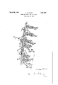
Having in view these Objects and others which will be pointed out in the following description, I will now refer to the drawing, in which y The gure is a view Vin perspective showing my invention. Y
The frame of implement includes front and rear beams 10 and 11 which are rigidly maintained in parallel and spaced apart relation. The rear beam 11 Vis braced at 12 and 13. The rear beam also supports forwardly projecting brackets having bearings in their forward ends for supporting the front beam 10. The rear beam 'also carries depending brackets for supporting the individual cul- .tivator gangs as will be subsequently de-` scribed.
Each gang includes a pair vof furrow guide Pivotally secured to bothyokes of a gang lis a transverse beam 16 which supports the is not here shown'since it is no part of the present invention. The details of the gangs are fully disclosed inthe Patent No. 1,7415,- 740, issued Februarylii, 1930,l to which refof the gangs.- As shown'in the drawing the two end gangs' thus have free movements on `the frame transversely of the frame, there- 4maintains the implement frame vin centered wheels lli'individually carried in yokes 15. l
erence-'is made( The present invention is :largelyuan adaptation ,ofthe gangs of that c'ultivatorl for use in a three-rowfcultivator.
y The rear beam 11 has two pairs of dependbrackets 20. The brackets 19 are in yoke form for supporting the rods 21, the brackets having spools 22 journalled therein for receiving the 'thrust from the rod 21.' The lateral movement ofthe furrow guide wheels 14 v'ing brackets-19` andv one pair of depending-*55 in the furrow is thus transmitted to the rod 21 vwhichis free to'move transversely of the beam, the spools 22 serving as antifriction devices to facilitatethe automatic adjustment sult Ybeing 'that `these. twol gangs will'be ceny tered overthe corn row regardless of 'the movements of the frame in relation tothe corn .rows during-cultivation. The central gang,V however, isssecured against lateral movements of the rod 21a by means of pins 23 which projectfrom the rods and which are adapted to slide up and down inthe elonggatedvertical slots-I of the brackets 20. The
however; is provided withl-fury `row guide wheels Vwhich maintain'the direcsmgle gang,
tion of movementof the gang in alignmentL with the corn row. Since this movement cannot take place independently of the implement frame, the movement must be trans- `-mitted to the implement frame. The result is that'the central gang thus automatically Y relation with the corn row. The elongated slots in the bracket 2O permit a floating movement. for the rod 21a-and consequently for the entire central'gang.
Secured to the front beam 10 is a lever 24:' Within convenient reach of the Operator. The
ofthe `beam 10 about its longitudinal axis.`
VThebeam 10 is also provided-'with connec- `tions at 25 for rocking the gangsabout the purpose of this lever is to permit the rockingv Van Having thus described my invention in such full, clear, and exact terms that its construction and operation will be readily understood by others skilled in the art to which it pertains, what I claim as new and desire to secure byl Letters Patent ofthe United States is: Y
l. A three-row listed corn cultivator including an implement frame, slotted brackets depending from said frame, a cultivat'organg secured iii said slotted brackets for'free movement in a vertical plaiiesaid gang including a pair of furrow guide wheels for maintaim ing the travel of said frame iii-alignment with a furrow, a pair of cultivator gangs positioned at opposite ends ofvsaid frame, two pairs of brackets depending from said frame, saidlast named brackets-being provided with apertures in transverse alignment7 antifriction devices in the apertures of said last y named brackets, rods supported in saidaper-r tured brackets for slidable movement transversely of the line of draft, a pair of cultivator gangs supported on said rods, and
furrow guide wheels on said last named cultivator gangs for automatically maintaining the travel of said last named gangs in alignment with the'furrows independently ofthe movements of said first named gang.
2. In combination, an implement frame, a
cultivator gang secured to said frame for automatic up and down'adjustment relative to said frame in response to the ridges and depressions of the field, a second cultivator gan g secured to said frame for automatic lateral adjustment relative to said frame in'response to variations in the. distance between two'furrows of the field, ineansforindividually lifting or lowering said two gangs, and means for simultaneously raising or lowering both Aof said gangs, said two raising or lowering means being independent of each other.
In testimony whereof I afiix my signature.
LE ON W. CHASE.
Priority Applications (1)
| Application Number | Priority Date | Filing Date | Title |
|---|---|---|---|
| US389566A US1851494A (en) | 1929-08-30 | 1929-08-30 | Three-row listed corn cultivator |
Applications Claiming Priority (1)
| Application Number | Priority Date | Filing Date | Title |
|---|---|---|---|
| US389566A US1851494A (en) | 1929-08-30 | 1929-08-30 | Three-row listed corn cultivator |
Publications (1)
| Publication Number | Publication Date |
|---|---|
| US1851494A true US1851494A (en) | 1932-03-29 |
Family
ID=23538788
Family Applications (1)
| Application Number | Title | Priority Date | Filing Date |
|---|---|---|---|
| US389566A Expired - Lifetime US1851494A (en) | 1929-08-30 | 1929-08-30 | Three-row listed corn cultivator |
Country Status (1)
| Country | Link |
|---|---|
| US (1) | US1851494A (en) |
Cited By (1)
| Publication number | Priority date | Publication date | Assignee | Title |
|---|---|---|---|---|
| CN103069940A (en) * | 2013-01-06 | 2013-05-01 | 广西壮族自治区水力机械研究所 | Reverse rotary tillage high-wide-ridge ridging mechanism |
-
1929
- 1929-08-30 US US389566A patent/US1851494A/en not_active Expired - Lifetime
Cited By (1)
| Publication number | Priority date | Publication date | Assignee | Title |
|---|---|---|---|---|
| CN103069940A (en) * | 2013-01-06 | 2013-05-01 | 广西壮族自治区水力机械研究所 | Reverse rotary tillage high-wide-ridge ridging mechanism |
Similar Documents
| Publication | Publication Date | Title |
|---|---|---|
| US1851494A (en) | Three-row listed corn cultivator | |
| US1746606A (en) | Tractor drawbar cultivator | |
| US1893619A (en) | Earth working implement | |
| US1541955A (en) | Motor cultivator | |
| US1944939A (en) | Combined row maker and coverer | |
| US1453944A (en) | Cultivator and harrow | |
| US1583451A (en) | Gang frame for agricultural implements | |
| US1611511A (en) | Cultivator | |
| US2053618A (en) | Agricultural implement | |
| US1831990A (en) | Cultivator attachment for tractors | |
| US1776242A (en) | Motor cultivator attachment | |
| US622348A (en) | Elias haiman and clark bishop | |
| US1619857A (en) | Disk harrow | |
| US673788A (en) | Spring-tooth harrow. | |
| US1718773A (en) | Tractor cultivator | |
| US1643567A (en) | Combined plow and cultivator | |
| US2414175A (en) | Coulter mounting for listers | |
| US2086797A (en) | Tractor lister cultivator | |
| US1613079A (en) | Cultivator | |
| US1944829A (en) | Bean harvester | |
| US1611726A (en) | Disk harrow | |
| US1648639A (en) | Tractor-drawn cultivator | |
| US1769142A (en) | Cultivator | |
| US2038438A (en) | Harrow | |
| US1745740A (en) | Combined listed corn cultivator and ridge leveler |