US1851468A - Locomotive - Google Patents
Locomotive Download PDFInfo
- Publication number
- US1851468A US1851468A US437334A US43733430A US1851468A US 1851468 A US1851468 A US 1851468A US 437334 A US437334 A US 437334A US 43733430 A US43733430 A US 43733430A US 1851468 A US1851468 A US 1851468A
- Authority
- US
- United States
- Prior art keywords
- seat
- locomotive
- controls
- clutch
- plant
- Prior art date
- Legal status (The legal status is an assumption and is not a legal conclusion. Google has not performed a legal analysis and makes no representation as to the accuracy of the status listed.)
- Expired - Lifetime
Links
- 230000003137 locomotive effect Effects 0.000 title description 22
- 230000005540 biological transmission Effects 0.000 description 6
- 238000002485 combustion reaction Methods 0.000 description 2
- 230000009977 dual effect Effects 0.000 description 2
- 241000287181 Sturnus vulgaris Species 0.000 description 1
- LYKJEJVAXSGWAJ-UHFFFAOYSA-N compactone Natural products CC1(C)CCCC2(C)C1CC(=O)C3(O)CC(C)(CCC23)C=C LYKJEJVAXSGWAJ-UHFFFAOYSA-N 0.000 description 1
- 238000010276 construction Methods 0.000 description 1
- 238000009432 framing Methods 0.000 description 1
- 238000012423 maintenance Methods 0.000 description 1
- 230000007935 neutral effect Effects 0.000 description 1
- 239000002699 waste material Substances 0.000 description 1
Images


Classifications
-
- B—PERFORMING OPERATIONS; TRANSPORTING
- B61—RAILWAYS
- B61C—LOCOMOTIVES; MOTOR RAILCARS
- B61C17/00—Arrangement or disposition of parts; Details or accessories not otherwise provided for; Use of control gear and control systems
- B61C17/12—Control gear; Arrangements for controlling locomotives from remote points in the train or when operating in multiple units
-
- Y—GENERAL TAGGING OF NEW TECHNOLOGICAL DEVELOPMENTS; GENERAL TAGGING OF CROSS-SECTIONAL TECHNOLOGIES SPANNING OVER SEVERAL SECTIONS OF THE IPC; TECHNICAL SUBJECTS COVERED BY FORMER USPC CROSS-REFERENCE ART COLLECTIONS [XRACs] AND DIGESTS
- Y10—TECHNICAL SUBJECTS COVERED BY FORMER USPC
- Y10S—TECHNICAL SUBJECTS COVERED BY FORMER USPC CROSS-REFERENCE ART COLLECTIONS [XRACs] AND DIGESTS
- Y10S100/00—Presses
- Y10S100/903—Pelleters
- Y10S100/906—Reciprocating
Definitions
- the inventionflcontemplate s a unified control arrangement convenient for forward. andflreverse operation novel and improved means of connecting the control members with the operating mechanism of the locomotive; a dual control arrangement with little or no increase inthe number of parts-required; a double seating arrange- 5 ment in the cab with controls operated readily from either seat; and other features of construction and resultant operating and.
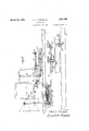
- F gure 2 is impart a rear elevation, and in part a transverse sectionon line 21-2QfFig'.
- braces 4, 4 4.
- the cab in addition to rear door 16 and side windows 17, is provided, preferably at each side, with a front window ISIa-nd a rear window 19, and at one side of the cab i 7 (here shown as the left'sidelis apai-r of seats 20, facing towardzeach other, and each supported beneath a window (l8-or l9 as the case maybe) 011a suitable-frame 21,1so that,
- thev cab deck actuates,throu ghconnection 26, the forwardly extending rod sectiOnS'Ql,
- the throttle lever 67 preferably mounted at "the left adjacent the seat opposite that first-mentioned.
- a power-plant, control means, and a pairo'f seats, part; of said control means'being positioned out of the way beneathon e seat and operable from the other seat, and anotherpart of said control means the being oppositely arranged andbeneath 2.
- a locomotive having an internal combustion motor for driving the same, a clutch, a transmission including reversing means, a single set of controls for the latter, and a double set of controls for the clutch, the transmission and reversing means with one clutch control being operable from one position, and the saidlast-mentioned means with the other clutch control being operable from another position, the two clutch controls being interconnected and having common means tend-V ing to hold them in clutch-engaged position.
- a locomotive including a power-plant and a cab and two oppositelyarrangedseats in the cab, and a single set of controls for the power-plant constructed and positioned for actuation from either of said two seat locations in said cab; one seat, the controls between the seats, and the other seat, being positioned serially in thatorder,lengthwise of the locomotive, and to one side of said" lengthwise of the locomotive, and to one side of said power-plant, whereby'clear vision 7 along the side of the power-plant is effected.
- -8 Ina self-propelled railway vehicle, opposite, forward and reverse "tioned seats,
- a locomotive including a power-plant and a cab, and a single set of controls for the power-plant constructed and positioned for actuation from either of two seat locations, together with forwardly and rearwardly-po' sitioned seats in said cab adjacent said controls; one seat, the controls between the seats,
- a locomotive including a power-plant and a cab, and a single set of controls for the 7 power-plant constructed and positioned for actuation from either of two seat locations, together with forwardly and rearwardlypositioned seats adjacent said controls, and suitable apertures in the cab aligned, respectively, one with each seat for clear vision c therefrom; one seat, the controls between the 7 seats, and the otherseat, being positioned,
Landscapes
- Engineering & Computer Science (AREA)
- Automation & Control Theory (AREA)
- Transportation (AREA)
- Mechanical Engineering (AREA)
- Seats For Vehicles (AREA)
Description
March 29, 1932. J TOWNSEND 1,851,468
LOCOMOTIVE Filed March 20, 1930 3 Sheets-Sheet 1 INVENTOR March 29, 1932. A. J. TOWNSEND LOCOMOTIVE 3 Sheets-Sheet 2 Filed March 20, 1950 A TTORNEYJ March 29, 1932. A. J. TOWNSEND LOCOMOTIVE Filed March 20, 1950 3 Sheets-Sheet 1V l [iN TO A Wa 70W W+ 4 TTOANE 1y Patented Mar. 29, 1932 1 'uNrreo stares" PATENT F I E-v 1 ALBERT, J; rowivsnnn'or LIMA, OHIO LOCOMOTIVE Y [A lication filed March-20, 1930. serial 11 5437334.
reverse running as forward running, and the invention is thereforeherein illustrated as applied to anindus'trial locomotive, the particular locomotive shown being of the internal-combustion powered type. y I One of the primary objects of the invention isto provide full and flexible control of the locomotive whether operating forwardly or in reverse; and, coupled withthis: to simplify and make safer the operation of the lolcomotive'and the shuntingof cars, to provide a more convenient'and comfortable cab arrangement, to insure proper vision ahead when operating in either direction, and to accomplish the foregoingwithout waste of cabspace. l i
I, More specifically, the inventionflcontemplates a unified control arrangement convenient for forward. andflreverse operation novel and improved means of connecting the control members with the operating mechanism of the locomotive; a dual control arrangement with little or no increase inthe number of parts-required; a double seating arrange- 5 ment in the cab with controls operated readily from either seat; and other features of construction and resultant operating and.
maintenance advantages as will more fully 401 hereinafter appear.
How the foregoing objects and advantages,
together with others which are incident to the invention or which may occur to-those familiar with this art, are obtained, will be clear from the following description taken tain partsof the cab and framebroken away the locomotive-ofFigsfil 'and 2, but onfaj still larger scale.
to show vnumerous {details of the constructiony' v V I V,
1 ofthe locomotive there illustrated,but'on '55 an enlarged scale;.and i L Figure?) is a fragmentary plan view ofthe control mechanism and associated parts of fReferring firstl 'to FigsjQl and an will b'e seen that the locomotiveingeneralzis of the four-wheel gasoline-engined type, having wheels 2, outer and inner longitudinalafraine members, 3, 4; end frame member'sfi, deckor 5 floor 6' which may be covered in th'ecab'by boarding- 7, cab 8, engine hood; "9 gasoline ymotor'lO, clutch and" gear casesorfho'usings 11', 12, and engine exhaust outlet orfstack ,13, the engine, clutch-case andgeair-boir being'conveniently mounted, in part forwardly Y of the cab and in part'therebeneath,betweenthe lnner .longitudinal fframe inembers'i. or
braces 4, 4. The locomotive framing,'thepar n ticular mounting "therein of "the, aforemen- A tioned parts, and'fthe drive connections from the transmission case to the longitudinal drive fshaft14 whichis gearedto axles 1'5, 7 need not ,be here illustrated or described in detail, as they form per se' noipartof. thep'resent invention, but the'same are fully disclosed and claimed in my co-pending applications No. 441,208,filed April 3, 1930; and N'o3472; (Sat filed August 2,1930; t Y 1 "z From the drawings in general, it will be seen that the cab, in addition to rear door 16 and side windows 17, is provided, preferably at each side, with a front window ISIa-nd a rear window 19, and at one side of the cab i 7 (here shown as the left'sidelis apai-r of seats 20, facing towardzeach other, and each supported beneath a window (l8-or l9 as the case maybe) 011a suitable-frame 21,1so that,
,in forward o peration'the engineer sits on the rear seat 20 and has a v ew through, w ndow .18, while in reverse operatlonthe' engineer may sit on the front: seat 20. withfvision through window 19.
4- Between theseats, anclwithin raay iea h l i 4 c ,1 r I h a V i V r i 1' from either, various controls are placed, as :3
, thev cab deck) actuates,throu ghconnection 26, the forwardly extending rod sectiOnS'Ql,
follows, (the positions described being with relation to the rear seat, as in Fig. 2)
' A vertically-extending reversing lever 22, at the right of the seat, extends upwardly from its fulcrum 23 which is secured. by the bracket 24 to the inner side of the left inner .frame member 4, and said'lever by forward and backward movement (in slot25 through 28, which in turn are linkedby aniadjustable connection 29 to rod30 and lever 31,. the latter acting as a crank to turn shaft 32-which extends into transmission case 12 andactuates a reversing gear (not shown) "A springpressed ballaor plunger 33 [(seeFig. 3.) is
fixedly mounted, for engagement with Jforward, neutral and reverse notches 34 on rod 'memlier 28, "said member. being preferably mounted for fore and aft sliding;movement in -fiic'ed'guides. e
A gearlever 35,, provided'adjacent the reverse lever 22, (inovablein the floor slot 36) is 'mounted in the bracket 24:, which serves also as ajhousing forflany suitable selector means, .-with.,.whi ch;t he lever may be engaged by .movementforwardly and rearwardly, to- .warld the :andvtoward the left,the selectorstndtshownl. aotuating rods 37, 38 and I3Q, cran'ks 40, .41 and 42, and cross shafts 43,
{44,to s u-itablyfmove the transmission gears ,neath seats 20p2 0,are provided clutchlevers 45,a, actuable by pedals 46, 46 64, the former from the front seat .and the. latter from the f.rearf.seat,f'said levers being, respectively, I mounted fast on rock-shafts .47, 47a, supi52, 53, and link v54 connect rock-shaft 47 to Eportdbn brackets 48, 49 50 and 51. Cranks 'rockshaft l'm whichelatter, in turn,carries a \crankearm 5 5, connected, through rod 56 to lever 57 mounted fast on the rock-shaft 58.
The latter is mounted onclutch-case 11 and actuates the clutch through the usual connections (not shown); To maintain thepedals -46,46 a,in their upper positioniand the clutch :inengagement, a spring 59, 're-acting against 7 Y-a fiXed support 60, bears-against a plate 61 -which presses against a nut: 62 adjustably threaded on rod 63, the latterbeing pivotally V secured to leverfietwhich is fast-on shaft 58.
single adjustable pressure device for the clutch and "both clutch pedals is'thus proyided; and an adjustable stop or abutment, 1n: theform'of thefiXed rods 65 and adjusting inuts66, may also be employed.
, As seen in Fig. 2,..the throttle lever 67 preferably mounted at "the left adjacent the seat opposite that first-mentioned.
side-wall 68 of the cab, and the brake-valve 69 and associated piping 70 (illustrated fragmentarily) is preferably mounted at the right on a standard 71 adjacent the gear lever 35, although these two controls may as readily be reversed in their locations.
It should here be understood that certain parts described above are not; illustrated in all the views, and that the throttle and brake controls are shown only in Fig. 2, in order to;
avoid 'confusion in the drawings.
:It will now be evident that, in operation of thelocomotive, when running forwardly the engineer sits in rear seatj20 and, with his fright foot on clutch pedal 46a and left hand on throttle lever 67,placesreversel lever 22 in; the forward position "(with his :right I hand) and then operates the gearlever 35,
clutch pedal 46a and, throttle67 withhis right hand, right foot .and left hand, respectively, and in: stopping, manipulates the brakevalve 69 with his righthandn From the-opposite seat, when running backward, all-the controls are equally accessible, but p rated by the. opposite hands, theclutchpedalafl being p0 ,sitioned properly for the right foot. All the controls, therefore, except the clutch control,
"are single controls adapted ffor dualoperation, and even the two clutch pedals operat but a single clutch.
.-In addition't'otheiforegoing it shouldb observed that the various control elements and the two seats are all compactly arranged at. one side of thecab and substantiallyin line with the fore and aft windows on that side. Furthermore, the arrangementis such that the clutch apparatus is mainly located between the longitudinal framelm embersj 3,
4, while the transmission apparatus is main- -ly located inside the plane of frame member,
4, and that these "frame members, particu-' I larly the latter, are nicely utilized to support the structure', as by brackets and the like,
and serve also to keep the various partsof the control mechanismproperly rigidly posin tioned with respect tothe'power-.p lant' and" transmission-casing, which latter are rigidly supported between the two nner frame memj V bers 4, 4.
i 'It'is therefore clear that the entire'arrange ment is a'uni fied and compact one, in which the various parts neatly co-opera-te to attain the desired objects.
What is claimed as 'new,'and desired to be secured by Letters Patent, "is:
1. In-a locomotive, a power-plant, control :means, and a pairo'f seats, part; of said control means'being positioned out of the way beneathon e seat and operable from the other seat, and anotherpart of said control means the being oppositely arranged andbeneath 2. In a locomotive, apower-plant, control a means, and a pair of'seats, part of said 0011- 1 V j trol means beingpositioned out of the way 1 I beneath one seat and operable from the other seat, andanother part of said control means being oppositely arranged and beneath the seat opposite that first-mentioned, said parts being paired together for joint operation of a control element. 7
3. A locomotive having an internal combustion motor for driving the same, a clutch, a transmission including reversing means, a single set of controls for the latter, and a double set of controls for the clutch, the transmission and reversing means with one clutch control being operable from one position, and the saidlast-mentioned means with the other clutch control being operable from another position, the two clutch controls being interconnected and having common means tend-V ing to hold them in clutch-engaged position.
'4. A locomotive including a power-plant and a cab and two oppositelyarrangedseats in the cab, and a single set of controls for the power-plant constructed and positioned for actuation from either of said two seat locations in said cab; one seat, the controls between the seats, and the other seat, being positioned serially in thatorder,lengthwise of the locomotive, and to one side of said" lengthwise of the locomotive, and to one side of said power-plant, whereby'clear vision 7 along the side of the power-plant is effected. -8. Ina self-propelled railway vehicle, opposite, forward and reverse "tioned seats,
control mechanism for thave and a plu- I" rality of controls for actiigtingsaid mechanism, located between the'seat'sl and positioned, 1 v n for convenient operation some by, the handand some by the left, from one seat, and
vice-versa from the opposite seat, together with driving mechanism including a single that order, lengthwise of the locomotive, and
clutch and dual clutch controls each POSl- 'tioned for operation from one of said seats;
toone side of saidpower-plant, whereb clear vision along the side of the power-p ant is effected. V V
Intestimony whereof I have hereunto signed myname. v I A'LBERT J TOWNSEND.
power-plant, whereby clear vision along the side of the power-plant is effected.
5. A locomotive including a power-plant and a cab, and a single set of controls for the power-plant constructed and positioned for actuation from either of two seat locations, together with forwardly and rearwardly-po' sitioned seats in said cab adjacent said controls; one seat, the controls between the seats,
and the other seat, being positioned serially in,
' 7 that order, lengthwiseof the locomotive, and
to one side of said power-plant, whereby clear visionalong the side of the power-plant is effected. Y
6. A locomotive including a power-plant and a cab, and a single set of controls for the 7 power-plant constructed and positioned for actuation from either of two seat locations, together with forwardly and rearwardlypositioned seats adjacent said controls, and suitable apertures in the cab aligned, respectively, one with each seat for clear vision c therefrom; one seat, the controls between the 7 seats, and the otherseat, being positioned,
serially in that order, lengthwise of the locomotive, and to one side of said power-plant, whereby clear vision along the side of the power-plant is effected. p
7. In a self-propelled railway vehicle, opposite, forward and reverse positioned seats, control mechanism for the vehicle, and a plurality of controls for actuating said ,mecha-. nism, located between the seats and positioned for convenient operation some by the right hand and some by the left, from one seat, and
vice-versa from the opposite seat; one seat, 7
the controls between the seats, and the other seat, being positioned serially in that order, 7
Priority Applications (1)
| Application Number | Priority Date | Filing Date | Title |
|---|---|---|---|
| US437334A US1851468A (en) | 1930-03-20 | 1930-03-20 | Locomotive |
Applications Claiming Priority (1)
| Application Number | Priority Date | Filing Date | Title |
|---|---|---|---|
| US437334A US1851468A (en) | 1930-03-20 | 1930-03-20 | Locomotive |
Publications (1)
| Publication Number | Publication Date |
|---|---|
| US1851468A true US1851468A (en) | 1932-03-29 |
Family
ID=23736007
Family Applications (1)
| Application Number | Title | Priority Date | Filing Date |
|---|---|---|---|
| US437334A Expired - Lifetime US1851468A (en) | 1930-03-20 | 1930-03-20 | Locomotive |
Country Status (1)
| Country | Link |
|---|---|
| US (1) | US1851468A (en) |
Cited By (2)
| Publication number | Priority date | Publication date | Assignee | Title |
|---|---|---|---|---|
| US4155309A (en) * | 1974-01-28 | 1979-05-22 | Whiting Corporation | Convertible rail-highway traction vehicle control cab |
| US5217181A (en) * | 1992-02-28 | 1993-06-08 | Ussc Group, Inc. | Sliding support |
-
1930
- 1930-03-20 US US437334A patent/US1851468A/en not_active Expired - Lifetime
Cited By (2)
| Publication number | Priority date | Publication date | Assignee | Title |
|---|---|---|---|---|
| US4155309A (en) * | 1974-01-28 | 1979-05-22 | Whiting Corporation | Convertible rail-highway traction vehicle control cab |
| US5217181A (en) * | 1992-02-28 | 1993-06-08 | Ussc Group, Inc. | Sliding support |
Similar Documents
| Publication | Publication Date | Title |
|---|---|---|
| US1851468A (en) | Locomotive | |
| US3288239A (en) | Adjustable toeboard and control pedal for vehicles | |
| US2141267A (en) | Vehicle | |
| US20240294205A1 (en) | Motor vehicle and method for the reconfiguration of the motor vehicle | |
| US2245714A (en) | Transmission control mechanism | |
| US4366881A (en) | Flip-up control console | |
| US2638175A (en) | Starter brake for power cycles | |
| US2033433A (en) | Pedal mechanism | |
| US2074319A (en) | Steering and driving control for tractors | |
| US1351939A (en) | Shearing and mowing machine | |
| US1721290A (en) | Vacuum servo-brake for motor-driven vehicles | |
| US2117016A (en) | Control mechanism for automotive vehicles | |
| US2116666A (en) | Truck conversion | |
| US659078A (en) | Motor-vehicle. | |
| US1942181A (en) | Mechanism for controlling delivery vehicles | |
| US2621750A (en) | Brake and clutch supporting structure | |
| US727923A (en) | Controlling mechanism for motor-vehicles. | |
| US2233188A (en) | Multimotored vehicle driving unit | |
| US1341531A (en) | Automobile air-brake | |
| US1613864A (en) | Combination railroad car and power unit | |
| US1434993A (en) | Gear-shifting mechanism for motor vehicles | |
| US944556A (en) | Motor-vehicle. | |
| US1285076A (en) | Gear-shifting mechanism for motor-cars. | |
| US1452736A (en) | Brake | |
| US2013586A (en) | Device for changing gear |