US1851454A - Stacking apparatus - Google Patents
Stacking apparatus Download PDFInfo
- Publication number
- US1851454A US1851454A US245943A US24594328A US1851454A US 1851454 A US1851454 A US 1851454A US 245943 A US245943 A US 245943A US 24594328 A US24594328 A US 24594328A US 1851454 A US1851454 A US 1851454A
- Authority
- US
- United States
- Prior art keywords
- articles
- conveyor
- stacking
- article
- movable
- Prior art date
- Legal status (The legal status is an assumption and is not a legal conclusion. Google has not performed a legal analysis and makes no representation as to the accuracy of the status listed.)
- Expired - Lifetime
Links
- 230000003028 elevating effect Effects 0.000 description 19
- 210000003414 extremity Anatomy 0.000 description 3
- 230000000284 resting effect Effects 0.000 description 3
- 230000000994 depressogenic effect Effects 0.000 description 2
- 230000000717 retained effect Effects 0.000 description 2
- 210000001364 upper extremity Anatomy 0.000 description 2
- PXMNMQRDXWABCY-UHFFFAOYSA-N 1-(4-chlorophenyl)-4,4-dimethyl-3-(1H-1,2,4-triazol-1-ylmethyl)pentan-3-ol Chemical compound C1=NC=NN1CC(O)(C(C)(C)C)CCC1=CC=C(Cl)C=C1 PXMNMQRDXWABCY-UHFFFAOYSA-N 0.000 description 1
- 241001625915 Aulostomus maculatus Species 0.000 description 1
- 239000000853 adhesive Substances 0.000 description 1
- 230000001070 adhesive effect Effects 0.000 description 1
- 238000013459 approach Methods 0.000 description 1
- 230000001174 ascending effect Effects 0.000 description 1
- 239000002131 composite material Substances 0.000 description 1
- 230000000694 effects Effects 0.000 description 1
- 239000010985 leather Substances 0.000 description 1
- 210000003141 lower extremity Anatomy 0.000 description 1
- 239000002184 metal Substances 0.000 description 1
- 229920000136 polysorbate Polymers 0.000 description 1
- 230000000630 rising effect Effects 0.000 description 1
Images

Classifications
-
- A—HUMAN NECESSITIES
- A43—FOOTWEAR
- A43D—MACHINES, TOOLS, EQUIPMENT OR METHODS FOR MANUFACTURING OR REPAIRING FOOTWEAR
- A43D117/00—Racks for receiving or transporting shoes or shoe parts; Other conveying means
-
- A—HUMAN NECESSITIES
- A43—FOOTWEAR
- A43D—MACHINES, TOOLS, EQUIPMENT OR METHODS FOR MANUFACTURING OR REPAIRING FOOTWEAR
- A43D111/00—Shoe machines with conveyors for jacked shoes or for shoes or shoe parts
- A43D111/006—Shoe machines with conveyors for jacked shoes or for shoes or shoe parts with special means to place the shoe or shoe part in the following machine
-
- Y—GENERAL TAGGING OF NEW TECHNOLOGICAL DEVELOPMENTS; GENERAL TAGGING OF CROSS-SECTIONAL TECHNOLOGIES SPANNING OVER SEVERAL SECTIONS OF THE IPC; TECHNICAL SUBJECTS COVERED BY FORMER USPC CROSS-REFERENCE ART COLLECTIONS [XRACs] AND DIGESTS
- Y10—TECHNICAL SUBJECTS COVERED BY FORMER USPC
- Y10S—TECHNICAL SUBJECTS COVERED BY FORMER USPC CROSS-REFERENCE ART COLLECTIONS [XRACs] AND DIGESTS
- Y10S414/00—Material or article handling
- Y10S414/10—Associated with forming or dispersing groups of intersupporting articles, e.g. stacking patterns
- Y10S414/102—Associated with forming or dispersing groups of intersupporting articles, e.g. stacking patterns including support for group
Definitions
- My invention relates to apparatus for forming various articles into piles or stacks, it being herein illustrated as applied to the arranging of sole-portions, ⁇ as those of insoles, in a magazine.
- t is also desiredv to dispose the articles in a definite position upon the delivering means to receive theactionV of thevstacking means.
- a Soles or sole-portions should have'l theirA longitudinal axes so positionedthat they correctly enterr a magazine elongated in one of its transverse dimensions.
- My improved apparatus includes means lfor effecting this positioning'action, preferably by contact ofu the articles uponthe delivering means With a gate or gates, which arrest them, or with the stacking means itself. When plural gates are used, there is obtained ajsuccessiveY control of the articles delivered from one gate to antraveling deliveringme'ans, ⁇ there may .bel re# taining means at .its opposite sides, and to.
- This supporting means ltravels horizontally,y and is Withdrawn ⁇ from the path ofthe elev vating membenasthis delivers articles to ther stack, and then is returned to support; said,v
- a frame 10 At the top of a frame 10 (Fig. 3) is a horizontal table 12, from nearvone extremity of which rises a casing 14;. At its top, this casingl is arranged toreceivea vertically extending magazine-tube 16,' which maybe of sheet-metal, and the lower extremity of Which may be closed by a slideV 18 to facilitatethe removal of the tube When it has. been flled.
- Both the casing ⁇ and the' tube are rectangular in ,horizontal section, and lare elongated transversely of the tableto receivein the present instance, such insoleportions asy thin leather blanks, .with their longitudinalaxes lying in the direction mensionf Y Y c
- the articles to be stacked are delivered to of this maximum dithe bottom of the casing a primary con-i v'eyor, shovvn as consisting of a series 4of sep- ⁇ arated belts 20, running in grooves inthe tai ble beneath the magazine, and being supportaV ed upon rolls22 and 24 at itsopposite eX-.
- sprocket-gearing 34 the latter connecting the shaft 3.2" to thes'haftcarrying'the*rolls 24j; Tighteners-S may be used to maintain-the belts 2Ol under the desired tension.
- the Work-pieces are brought by a .sec-l ondary 'conveyor 36 which maybe one' upon which theyhave been carriedior aV considerable distance, so that an adhesive with which they have beenY coated has been allowed to'at least partially dry.
- VI have shown the conveyor 36 as driven from the adjacentv Y shaft-@of rolls -22bysprecketfgearing .3T atk ai i l the-f conveyor T36. 'f Moving. atieach-e side -oi ⁇ the speed? considerably 'less than that' of ther conveyorrQO. Therefore, Whenueach article is.
- brackets-v 38 i aref rneuntedl in'ay be adjustable up on? the:
- supporting lingers 54 are movablehorizontally through openings in said casing.
- the fingers are preferably arranged in two sets, at. the front and rear of the casing, and extend be-Y tween .the longitudinal series of elevating,
- vThetime-ref lation 'between theV movements yof the elevating pins and the supporting fingers may be as follows, it existingifoi'V yeach article vstacked 1 Assumingthe -pinstobeatthe "lqwestlpoint in@ ⁇ their; reciprocation, y the endsy of .the opposite sets yof lingers will be inproXirnit-y to eneaan-' other,thusiextendingbeneath the stack in .the n casing-and tube andsupportingfit.- Anarti- ⁇ cle being, delivered-,- above .the pinsby they: 'conf4 *Y veyorQO, .said pins rise, and, as vthe articlethey bear approaches thev under sides-of the fingers', theseseparate rapidly, gg-ivi-n-g1 a space throu'ghwhich Vthel article Y isfjorcedagainst thebottom of the stack,the weight oflwhich is new
- the gate 80 has joined to its slides arms 92 fixed upon a shaft 94 turning in its standards.
- An arm 96. and link 98 connect this shaft to an arm 100 fast upon a shaft 102 j ournaled in the frame beneath the table.
- An arm 104 upon shaft 102 has a roll 106 operating in a groovein a cam-disk 108 secured to a transverse shaftllO.
- the gate 82 is similarly oined through arms 112, shaft 11,4arm 116, link 118, lever 120 and roll 122 to a groove in a cam-disk 124 also fixed to the 'shaft 110'. ⁇ This shaft is rotated through gear-teeth upon :the periphery of the disk 124, which mesh with an idler pinion 126 rotatable upon the stud 72 and engaging, in turn, ⁇ teethl about the cam-disk 76'.
- the gates are so operated bytheir cams that they move simultaneously in opposite directions, one being open while the other is closed. ⁇ Because both the belts 20 and the articles they convey may vary in thickness, vthe gates 80 and 82.7are arranged to yield vertically, springs 83 being interposed between their links 98 and 118 and the levers which they actuate. The rate at which each gate completes a'cycle of movement is greater than that at, which articles can be delivered by thefsecondary conveyor 36.' There being a predetermined time-relation between the action of the inner gate 80 and the elevating pins, the articles are held by the former while the pins'are depressed, being preferably released by the rise ofthe gate just as the descent of the pins is beginning.
- this article is advanced by the conveyor into the casing above the pins, being retained until elevation by the contact of its forward edge with the casing-wall.
- the gate-82 is closed to retain the succeeding articleuntil 80 again closes, whereupon 82 rises for a sufficient length of time to free a single article.
- the apparatus' has means for adjusting the position of the articles upon the conveyor, this meansconsisting preferably of the gates, elevating pins and the forward casing-wall.
- eachof the gates-# is shown as having associated with ⁇ it a second gate-portion 130, which may extend somewhat lower thanV its companion and may beV mounted upon a "spring-support 132.
- gate 580 and the descent kof the pins 48from the position ⁇ of the latter illustrated in Fig. 2 of the drawings is such that the freed .article is carried against-the sides of the pins 48 While :these :are-still being lowered'.r As a resulil of this, as soon as the upper extremities of 'these pin's arebeneath the conveying surface, vthe article .is carried beneath the casingagafinst'its kforward wall, and there held for the rise of thel pins, vwhich at once follows.
- Va -stacking apparatus Aa stacking membermovable verticalilv to receive' and arrange"articles resting 'one upon another, means fordeliverin g the Aarticles ⁇ to the member, and means movable relativel7 to the delivering means and engagingarticles Vthereon to Lvcr'introlthe-ir delivery. l
- a stack-ing member movable vertically to' receive and ar- Y range articles rresting -one upon another
- vmeans for delivering articles 'tothe member means coperating with the delivering means for limitingthe deliveryto predetermined times, and driving means for operating lthe stacking member and limiting means :in definite vtime-relation.
- a stacking apparatus a movable stacking member, a conveyor having a traveling surface deliveringr to the stacking member, and a plurality of gatessituated above and movable toward and from the conveying surface and'ea-ch provided witha plurality of article-engaging projections, ⁇ said gates being YVarranged to act successively upon the articles carried by the conveyor.
- a movable sta-cking member In a stacking apparatus, a movable sta-cking member, an endless conveyorv delivering to the stacking member, a plurality of gates movable Yabove and, towardv andV fromv the'conveyor and arranged to actsuccessively upon the articles thereon, and means arranged tofmove adjacentgates4 in alternation.
- astacking apparatus meansgmovable to arrange articles in a stack, means'for'deportions is mounted.Y
- a stacking apparatus means movable'V to arrange articles in a stack, means for delivering thearticles to the stacking means, and a member movable relatively 'to thefdeiver-ing meansand providedv with plural p0rtions arranged to engage articles 'at points spaced from hone another upon'the member, one of said portionsbeing yieljdably mounted.
- a movable stack-support In a stacking apparatus, a movable stack-support, a movable stacking member delivering to the support, continuously operating means delivering articles to the stacking member, means co-operating with thedelivery means for controlling the delivery of articles thereby, and means for operating the support, stacking member and controlling means in definite time-relation.
- a stacking apparatus a plurality of article-elevating members spaced from one another, and a plurality of supports movable in the spaces between the members, said sup-v ports carrying the elevated articles resting upon one another in a stack.
- a stacking apparatus a plurality of article-elevating members spaced from one another, a plurality of supports movable in the spaces between the members, said sup- ⁇ ports carrying the elevated articles resting upon one another in a stack, and means for operating the elevating members and stacksupports in definite time-relation.
- a stacking apparatus a plurality of vertically-extending elevating members spaced laterally from one another, and opposite sets of stack-supporting fingers movable in the spaces between the members.
- a stacking apparatus a plurality of elevating members spaced from one another, opposite sets of stack-supporting fingers mova plurality of stack-supports movable in the spaces between the members, a plurality of conveyor-belts movable in said spaces, gates co-operating with the belts, and means for l I movingv said gates alternately to stop andrelease articles upon the belts.
- a stacking apparatus means for arranging articles in a stack, traveling means for delivering the articles to the stacking Vmeans,pmeans co-operating with the articles von the delivering means and arranged to p0- sition said articles thereon, ,andV article-retaining means traveling with the delivering means between the positioning means and the stack-arranging means.
- an elevating member In a stacking apparatus, an elevating member, a stack-support co-operating with Y the member, al conveyor-belt delivering to the elevating member, a gate movable into and out of the path of the articles upon the conveyor-belt, and belts furnishing retaining walls at opposite sides of the conveyor-belt between the gate and elevating member.
- a stacking apparatus a plurality of elevating members spaced from one another, a plurality of stack-sup Orts movable in the spaces between the mem ers, and a plurality of conveyor-belts movable in said spaces.
- a stacking apparatus In a stacking apparatus, a plurality of elevating members spaced from one another, a plurality of stack-supports movable in the 22. In a stacking apparatus, aplurality of elevating .members spaced from one another,
Landscapes
- Delivering By Means Of Belts And Rollers (AREA)
Description
March 29, 1932. R. c. slM'MoNs v STACKING APPARATUS Filed Jan. 11,-1928, 3 Sheets-Sheet 1 March 29, 1932. R. C slMMONs 1,851,454 I STACKING APPARATUS Filed Jan. 11, 1928 3 Sheets-Sheet 2 ff @w /Wf/ s Patented Mar. 29,` 1932 Y l, 4 UNrlazD STATES JERSEYA Y PATENT *orifice i RALPH asIMMONS, or BEVERLY, MASSACHUSETTS, AssIGNoR To UNITED sHoE MAQ CHINERY coaPoRATIoN, or PATERsoN, NEW
JERSEY, A CORPORATION 0F NEW sracxrNe ArPAaAfrUs Application mea Jaaary 11, 192s. .serial No. 245,943. i`
My invention relates to apparatus for forming various articles into piles or stacks, it being herein illustrated as applied to the arranging of sole-portions,`as those of insoles, in a magazine. Y i
In some machines employed in the making of soles, it may be desired to'supply them With portions upon which they are to operate 1n stacks contained in magazines. For example, itis convenient to handle in this Way the lay` ers which are to be `included i in composite insoles. An object of the'invention' is to pro# videV forthus stacking articles automatically and with speedand accuracy/.regardless of:
the rate at Whichthey are received. In attaining this object, I utilize,`,in novel combinations, stacking means, which may beinthev form of an elevating memberfor members, and
means for delivering tothe stacking means, Y
there co-operating Withthe delivering means other means `contacting with the articles, herein shown as gates movable relatively to the delivering means, for controlling the delivery o articles. This article-controlling. means may be so operated in ydefinite time# relation to the stacking means that, although the latter may be inmotion, articles will be delivered to itA only at predetermined times, when it is in the proper receiving relation. Thereis thus assured the ord-erlyperformance u on each article of the stacking operation. t is also desiredv to dispose the articles in a definite position upon the delivering means to receive theactionV of thevstacking means.A Soles or sole-portions should have'l theirA longitudinal axes so positionedthat they correctly enterr a magazine elongated in one of its transverse dimensions. My improved apparatus includes means lfor effecting this positioning'action, preferably by contact ofu the articles uponthe delivering means With a gate or gates, which arrest them, or with the stacking means itself. When plural gates are used, there is obtained ajsuccessiveY control of the articles delivered from one gate to antraveling deliveringme'ans,` there may .bel re# taining means at .its opposite sides, and to.
avoidfdisturbance of articlesafter they have been position-ed, this retaining means travels,
' With the delivering means between the positioning means and the stacking means. To maintain the accumulating articles in the, stack, and at the'same time allowjtheir suc-A cessive receptiomI providea stack-support movable. into and outot the path :of articleswhich are under the influence of the stacking or elevating member, andmeans for-moving ythis in definite time-relation to said member.
.This supporting means ltravels horizontally,y and is Withdrawn `from the path ofthe elev vating membenasthis delivers articles to ther stack, and then is returned to support; said,v
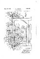
stack. It is illustrated-asincluding members movable oppositely. Y v i .The accompanying Vdrawings illustrate a particular embodiment of my; invention adapted for the stackingI of insoleportions Fig. 1 being a top plan view thereof; Y
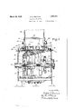
Fig, 2, aside elevation; andr Y j 4 i Fig. 3, a transverse vertical section ion the` line III-III of Fig. 2. j Y. a
At the top of a frame 10 (Fig. 3) is a horizontal table 12, from nearvone extremity of which rises a casing 14;. At its top,this casingl is arranged toreceivea vertically extending magazine-tube 16,' which maybe of sheet-metal, and the lower extremity of Which may be closed by a slideV 18 to facilitatethe removal of the tube When it has. been flled. Both the casing `and the' tube are rectangular in ,horizontal section, and lare elongated transversely of the tableto receivein the present instance, such insoleportions asy thin leather blanks, .with their longitudinalaxes lying in the direction mensionf Y Y c The articles to be stacked are delivered to of this maximum dithe bottom of the casing a primary con-i v'eyor, shovvn as consisting of a series 4of sep-` arated belts 20, running in grooves inthe tai ble beneath the magazine, and being supportaV ed upon rolls22 and 24 at itsopposite eX-.
tremities and rolls 2 6, 26 at'the bottom of the Y The conveyor-belts Vare driven con- Y frame. A tinuouslym the direction 'o'f'thejar-rowfinf Fig. 1 by a motor 28, which may be electrical. Power is transmitted through a pinion 29 on the shaft of the motor, a gear 80 on a shaft 32 journaled transversely of the frame, and
sprocket-gearing 34, the latter connecting the shaft 3.2" to thes'haftcarrying'the*rolls 24j; Tighteners-S may be used to maintain-the belts 2Ol under the desired tension. To these belts the Work-piecesare brought by a .sec-l ondary 'conveyor 36 which maybe one' upon which theyhave been carriedior aV considerable distance, so that an adhesive with which they have beenY coated has been allowed to'at least partially dry. VI have shown the conveyor 36 as driven from the adjacentv Y shaft-@of rolls -22bysprecketfgearing .3T atk ai i l the-f conveyor T36. 'f Moving. atieach-e side -oi` the speed? considerably 'less than that' of ther conveyorrQO. Therefore, Whenueach article is.
dropped upon `:the last-mentioned conveyor, it'r'isiat once' :carried awayl and 'r spaced vfrom the succeeding! article, which hasnot yet .left
the'extremitiesof lthe tablet` The brackets-v 38 i aref rneuntedl in'ay be adjustable up on? the:
franietoenabletliepropertensi'onfto"be main'- tail-led'i The' belts -are dri-ven Yatv substantiitlflyftihelspeed `offt'he :.conveyorbelts through spirali-gearing ylfffroni tliedrivenfshaft of the ti-vemovenient. Thatijsanarticlepositioned' relatioiife'fven- Iif in'. Contact with one' of? the 40 walls 38. This is .of especial importance with Y 'Y To'raise articles' from the `conveyor 20 to v elevating device A is provided. Thisfin' eludes ai slide 43 .movable in'vertical ways 44@ torina 'stack' the Acasing 1l .and `tube 116,
at` one side of the trame'andcarryinga hori zont'al pl'latetd-which extends beneath the inafrazilne y Set the plate'are vertical pins 48 urnishing elevating for stacking'members,` 'vthesepins passin'glthrough openings inthe tablefandbeing so spaced transversely :as to li lbetweenth'e belts 20. Longitudinally'of theta'ble, their spacingl isfpsuch as to afford 1 support iier't'he smallest ar'ticlesto bestacked.
Vertical tra-vel is irnpartedttothe pins, so-that they inove trompa positionv in which' their v upper ends are just beneath-the conveying su-rfacesof the beltsQOto'one at which these ends are'withinthe'casing 14 above said belts, byafcarn-groove 50 formed in the gear 30 andV egag'ed by a roll' 52 mounted upon the outerr Vsideoi the slide'lQp Thiselevation andden pression'of the'pins goes on continuous-lydur- Y ingfrtheoperation'of the'apparatus. Y 1' To 'retain the ele'vatedarticles in the fstack when the pins descend from'the casing, supporting lingers 54 are movablehorizontally through openings in said casing. The fingers are preferably arranged in two sets, at. the front and rear of the casing, and extend be-Y tween .the longitudinal series of elevating,
pins. Each setfis carried vby atransverse bar y56 iixednat each extremity upon a carrier 58 liungvupona pair of links 6,0, 62 pivoted'upon ofthe casing. 'The links 62aregearedto'gether' at'Gt, so that the `lingers vnuove opp'ositely, al- Y t-ernately approaching and receding from each other; :Turning with one pair of links is an arrn'GG joinedby aconnecting rod 68 to a. lever fulcrunied upon a stud 7 2 projectingiiroin theside of the trame; 'Ehe' levier carries airoll 74 entering a groeve inll afnam-f' disk 7.6 1fast1uponithe shaftBQ. vThetime-ref lation 'between theV movements yof the elevating pins and the supporting fingersmay be as follows, it existingifoi'V yeach article vstacked 1 Assumingthe -pinstobeatthe "lqwestlpoint in@` their; reciprocation, y the endsy of .the opposite sets yof lingers will be inproXirnit-y to eneaan-' other,thusiextendingbeneath the stack in .the n casing-and tube andsupportingfit.- Anarti-` cle being, delivered-,- above .the pinsby they: 'conf4 *Y veyorQO, .said pins rise, and, as vthe articlethey bear approaches thev under sides-of the fingers', theseseparate rapidly, gg-ivi-n-g1 a space throu'ghwhich Vthel article Y isfjorcedagainst thebottom of the stack,the weight oflwhich is new carried by thefpins. Mevementfofthe .pins being reversed Vvso that they descend, the
fingers are quickly thrust between them -beneath .the stack, furnishing asupport orit 'asrv the pins leave it to'elevate the succeeding arti cle.. Since the-supporting rneansispositively 'actuated and no pressure isrexerted bythe stacked 'articles to eect the movementthere is no danger of such articles becoming de o'rming-or-displaced in the stackduringtheir introduction.,- f f .The `operating cycle of the, pins' andiingers just vdescribed substantially agrees with` the rate at which the articles are delivered by the.. conveyor 20. There must, however, be suchV exactnessof relation between` this feed Aand j the elevati-ng action lof the pins that articles will not -bel cau-ghtin the ascenti'of thepins between them andthe edge :of the casing zbe.-V j
the vconveyor-belts 2O to alternately stop 4and n release'the adv.ancin'garticles. The `gate also,A
has -a positioning function as -tothe .angular relation of the 'articles ,upon the conveyor.'l l. prefer to-einploy a'plurality of these gates. second being shownat 82, which controls the delivery, tofitsmcompan-ion vand also acts te 82 are respectively mounted. upon-verticallyV movable slides 86, .of which .two are illustrated, guided ina yoke 88 connecting stand;-
`Because the articles upon which the present'apparatus is intended to operate are elongatedlin one direction; and since the casing and magazine-tube are arranged with the maximum horizontal dimension lying trans-` versely of the `conveyor 20, the apparatus'has means for adjusting the position of the articles upon the conveyor, this meansconsisting preferably of the gates, elevating pins and the forward casing-wall. 'If an article, whenit is stopped ,by one of these devices, is displaced angularly so that its longitudinal axis is not substantially at right angles toits direction of advance, the drag of the belts 20 upon the article as its forward extremity rests against the .member which has arrested it will Y Y cause t-he turning of its free end toward stop member;V VThe effect of this will depend upon the length of time the belts have to act' upon the partially arrestedar'ticle. But after `l this action has occurred two or threeA times, a Y
as at one or` both ofthe gates, atthe pins and insidevthecasing, itis reasonably certainthat the desired transverse relation will have been attained, and that an insole, for example, will rest with both its heel and toe,- portions in engagement with the pins when these are depressed to receive it for eleva-v tion into the stack.` It'may be. found that,
if a single gate stops lthe travel of an article by descending upon it ratherv'than in its path, the frictional eil'ect of the belts 20'will act to turn the article beneath the gate. This causes a departure from the proper angular relation, as-just described, which it might be impossible to fu'llyfcorrect,v at thelateracting devices.v To preventthis, eachof the gates-#is shown as having associated with `it a second gate-portion 130, which may extend somewhat lower thanV its companion and may beV mounted upon a "spring-support 132.
With this arrangement, if one of the gates contacts with the upperface of*` an article, the portion 130 engages it and then-'yields to permit contact of the associated member,Y Now, the gate will bear upon at least two y separated points and thus prevent rotation of the article. The correction of its angular position, if this is required, may then beeffected att-he succeeding devices. To-outline the general operation ofthel apparatus, it may be said that insole-portions or Vother articlesl are delivered one byv one from vthe 'conveyor 36 tothe conveyor 20. The lattercarries each article quickly away from the following articles upon them'ore slowly traveling conveyor 36, giving an uninterrupted period during which the gates ofnadvance, the contactfwith the gate l82 will wholly or partially correct this.,v When theV gate 80 is lowered, 82 lwillrise long enough to permitthe forwarding ofthe article 4into contact with the gate 80, where a further cor-V rection of the angular position may be made.r
Had the gate 82 been raised,'the article would Y i have passed atonce to the gate 80. In either case, if the contact of the gatewith the article occurs over the upperface, the plural y portions .will hold it against Vdisplacement asl a, result ofthe ,movementl of the `conveyor while it is thus retained. If the article is at ,i
one side `of the conveyor, so that itsextremity-` rests againstv a belt-38, there will befno dis-j placing tendency, on account of the? equal rate' of'travel of the beltsY 20 and 38.. f The time-.relation between the elevation :of .the
" gate 580 and the descent kof the pins 48from the position `of the latter illustrated in Fig. 2 of the drawings "is such that the freed .article is carried against-the sides of the pins 48 While :these :are-still being lowered'.r As a resulil of this, as soon as the upper extremities of 'these pin's arebeneath the conveying surface, vthe article .is carried beneath the casingagafinst'its kforward wall, and there held for the rise of thel pins, vwhich at once follows. At both the pinsand casing-wall there is affor-ded an 'opportunity for further'angular positioning.l Asthe ascending article appreaches` the vunderv `side of the fingers v541g, these are withdrawn, and the pins newv supporting both this article and the remainder of the stackcarry these above'the fingers.
Thereupon, the movement is reversed, the pinslbeing lowered and the ingersca-rried in beiieaith the stack in preparation for the ree'eption of the succeeding article.- When .a
' sufficient number kof the articles 'has accumulated withint'he tube 16, this may be removed and app-lied'to -themachinewhich is :to be' fed. I
v Having described my invention, what I claim as new and desire to .secure by Letter Patent Aof the United States is: v i
"1.. In Va -stacking apparatus, Aa stacking membermovable verticalilv to receive' and arrange"articles resting 'one upon another, means fordeliverin g the Aarticles `to the member, and means movable relativel7 to the delivering means and engagingarticles Vthereon to Lvcr'introlthe-ir delivery. l
2. In a Vstacking--a-pparatus, a stack-ing member movable vertically to' receive and ar- Y range articles rresting -one upon another,
vmeans for delivering articles 'tothe member, means coperating with the delivering means for limitingthe deliveryto predetermined times, and driving means for operating lthe stacking member and limiting means :in definite vtime-relation.
` 3. In a stacking apparatus, a movable stacking member, a conveyor having a traveling surface deliveringr to the stacking member, anda plurality of gatessituated above and movable toward and from the conveying surface and'ea-ch provided witha plurality of article-engaging projections,`said gates being YVarranged to act successively upon the articles carried by the conveyor.
. 4l. In a stacking apparatus, a movable sta-cking member, an endless conveyorv delivering to the stacking member, a plurality of gates movable Yabove and, towardv andV fromv the'conveyor and arranged to actsuccessively upon the articles thereon, and means arranged tofmove adjacentgates4 in alternation. f 5.. In astacking apparatus, meansgmovable to arrange articles in a stack, means'for'deportions is mounted.Y
Timing the articles mme Stacking means,
and means movable relatively toy the delivering .means and provided with plural portions arranged to engage simultaneously faces of articles atpoints 1spaced from one another, one of said engaging .means being `vyieldazble independently ofthe. associated engaging means. f Y
' .6. In a stacking apparatus, means movable'V to arrange articles in a stack, means for delivering thearticles to the stacking means, and a member movable relatively 'to thefdeiver-ing meansand providedv with plural p0rtions arranged to engage articles 'at points spaced from hone another upon'the member, one of said portionsbeing yieljdably mounted. 7. In a stacking apparatus, a movable stacking member, a. conveyor delivering to the stacking member, and a `yieldable gate movable toward and from the conveyor and hav- Y ing. a plurali-'ty of :article-engaging portions articles, and a spring upon which one of the Y 9; The combinationivith aymagazilne, of a' conveyor movable beneath the rmagazine, aA stacking member reciprocating from below the conveying surface into the magazine, and a gate movable in 'co-operation with the* conveyor to varrest the advance ofi-articlesV thereby. Y i y 1 Y l0. The combination with a'magazine, of a conveyor movable beneath the magazine, a
stacking lmember reciprocating-from below y the conveying surface mtothe'magazine, a Y
gate movable inV co-operation with the'V con-r veyor to arrest the advance of articles thereby, and means for lowering vthe gate to stoparticles upon the conveyor while the ,stacking member is lowered.'
l1.' The :combination withV a magazine, of
a conveyor movable beneath Athefmagazi-ne, a j stachm g member reciproca-ting 'from' below the Conveying surface 1ntoth'ef magazine,
gates successivelyV arranged along th 'e;conf veyor to change the relation of articles thereon, and means arrangedtoV simultaneously l' lower one'gate'and raise another.;
12.' The combination with azmagazine, of a conveyor movable'beneath the magazine, a stacking member reciprocating from below the `conveying surface ,into the magazine, gates `successively arranged lalong the Aconveyor, and means :arranged to lowerfthegate nearest the Vstacking member ywhen*thisgfi-s lowered and to raise the succeedi'nggate.V f,
13. 'In ya `*sta'cliriI-ig apparatus, a horizontally y vl reciprocating stack-support, an elevating member arranged to carry an article and movable to deliver said article to a. point above the support, and means arranged to withdraw the support from the path of the elevating member during the movement of said member.
14. In a stacking apparatus, a movable stack-support, a movable stacking member delivering to the support, continuously operating means delivering articles to the stacking member, means co-operating with thedelivery means for controlling the delivery of articles thereby, and means for operating the support, stacking member and controlling means in definite time-relation.
15. In a stacking apparatus, a plurality of article-elevating members spaced from one another, and a plurality of supports movable in the spaces between the members, said sup-v ports carrying the elevated articles resting upon one another in a stack.
16. In a stacking apparatus, a plurality of article-elevating members spaced from one another, a plurality of supports movable in the spaces between the members, said sup-` ports carrying the elevated articles resting upon one another in a stack, and means for operating the elevating members and stacksupports in definite time-relation. Y
17. In a stacking apparatus, a plurality of vertically-extending elevating members spaced laterally from one another, and opposite sets of stack-supporting fingers movable in the spaces between the members.
18. In a stacking apparatus, a plurality of elevating members spaced from one another, opposite sets of stack-supporting fingers mova plurality of stack-supports movable in the spaces between the members, a plurality of conveyor-belts movable in said spaces, gates co-operating with the belts, and means for l I movingv said gates alternately to stop andrelease articles upon the belts. v
23. In a stacking apparatus, means for arranging articles in a stack, traveling means for delivering the articles to the stacking Vmeans,pmeans co-operating with the articles von the delivering means and arranged to p0- sition said articles thereon, ,andV article-retaining means traveling with the delivering means between the positioning means and the stack-arranging means.
24. Ina stacking apparatus, means for arranging articles ina stack, traveling means for delivering thel articles to theV stacking means, means arranged to stop the advance of the articles by the delivering means and to position said articles in a definite angular relation thereon, and retaining walls traveling v with the positioned articles at opposite sides" of the delivering means between the position-v ing means and the stack-arranging means.
25. In a stacking apparatus, an elevating member, a stack-support co-operating with Y the member, al conveyor-belt delivering to the elevating member, a gate movable into and out of the path of the articles upon the conveyor-belt, and belts furnishing retaining walls at opposite sides of the conveyor-belt between the gate and elevating member.
VIn testimony whereof I have. signed my name to this specification. i
RALPH C. SIMMONS.
able in the spaces between the members, links e carrying the fingers, and connections between theV links of the opposite sets to compel them to move oppositely.
19. In a stacking apparatus, a plurality of elevating members spaced from one another, a plurality of stack-sup Orts movable in the spaces between the mem ers, and a plurality of conveyor-belts movable in said spaces.
20. In a stacking apparatus, a plurality of elevating members spaced from one another, a plurality of stack-supports movable in the 22. In a stacking apparatus, aplurality of elevating .members spaced from one another,
spaces between the members, a plurality of l
Priority Applications (1)
| Application Number | Priority Date | Filing Date | Title |
|---|---|---|---|
| US245943A US1851454A (en) | 1928-01-11 | 1928-01-11 | Stacking apparatus |
Applications Claiming Priority (1)
| Application Number | Priority Date | Filing Date | Title |
|---|---|---|---|
| US245943A US1851454A (en) | 1928-01-11 | 1928-01-11 | Stacking apparatus |
Publications (1)
| Publication Number | Publication Date |
|---|---|
| US1851454A true US1851454A (en) | 1932-03-29 |
Family
ID=22928728
Family Applications (1)
| Application Number | Title | Priority Date | Filing Date |
|---|---|---|---|
| US245943A Expired - Lifetime US1851454A (en) | 1928-01-11 | 1928-01-11 | Stacking apparatus |
Country Status (1)
| Country | Link |
|---|---|
| US (1) | US1851454A (en) |
-
1928
- 1928-01-11 US US245943A patent/US1851454A/en not_active Expired - Lifetime
Similar Documents
| Publication | Publication Date | Title |
|---|---|---|
| US3986319A (en) | Wrap-around packer | |
| US1851454A (en) | Stacking apparatus | |
| US2946164A (en) | Method of placing cartons into packing cases | |
| US2014458A (en) | Storage apparatus | |
| US1850151A (en) | Work-forwarding system | |
| GB1477093A (en) | Device for the continuous delivery of articles | |
| US1588156A (en) | Packing machine | |
| US1943444A (en) | Apparatus for separating articles | |
| US2946165A (en) | Method of and machine for forming packages | |
| US1978004A (en) | Transferring system | |
| US1535784A (en) | Trestle or container for receiving manufactured cigarettes | |
| GB936460A (en) | Stacking articles | |
| US823051A (en) | Packing-machine. | |
| US1251852A (en) | Feed mechanism. | |
| US3579953A (en) | Cigarette packers | |
| US1262335A (en) | Heel-press. | |
| US1352745A (en) | Means for feeding articles in stacked relation | |
| US3102285A (en) | Insole molding machines | |
| US2948434A (en) | Tray feeding apparatus | |
| US1854199A (en) | Separating apparatus | |
| GB1379884A (en) | Handling of biscuits | |
| US1048865A (en) | Match-unloader. | |
| US2096277A (en) | Packaging machine | |
| US1804071A (en) | Device for applying hooked clasps | |
| US2329071A (en) | Heel building machine |