US1851432A - Process of reclamation of crank case or used oils - Google Patents
Process of reclamation of crank case or used oils Download PDFInfo
- Publication number
- US1851432A US1851432A US477582A US47758230A US1851432A US 1851432 A US1851432 A US 1851432A US 477582 A US477582 A US 477582A US 47758230 A US47758230 A US 47758230A US 1851432 A US1851432 A US 1851432A
- Authority
- US
- United States
- Prior art keywords
- oil
- jacket
- tank
- reclamation
- oils
- Prior art date
- Legal status (The legal status is an assumption and is not a legal conclusion. Google has not performed a legal analysis and makes no representation as to the accuracy of the status listed.)
- Expired - Lifetime
Links
- 238000000034 method Methods 0.000 title description 9
- 239000010913 used oil Substances 0.000 title description 4
- 239000003921 oil Substances 0.000 description 21
- 239000000203 mixture Substances 0.000 description 11
- 239000004927 clay Substances 0.000 description 7
- 239000004744 fabric Substances 0.000 description 5
- 238000010438 heat treatment Methods 0.000 description 5
- 238000013019 agitation Methods 0.000 description 4
- 238000001914 filtration Methods 0.000 description 4
- 239000010687 lubricating oil Substances 0.000 description 4
- 238000010276 construction Methods 0.000 description 3
- 239000007789 gas Substances 0.000 description 3
- 239000000470 constituent Substances 0.000 description 2
- 238000005336 cracking Methods 0.000 description 2
- 239000000945 filler Substances 0.000 description 2
- 239000000446 fuel Substances 0.000 description 2
- 238000003475 lamination Methods 0.000 description 2
- 230000004048 modification Effects 0.000 description 2
- 238000012986 modification Methods 0.000 description 2
- OKTJSMMVPCPJKN-UHFFFAOYSA-N Carbon Chemical compound [C] OKTJSMMVPCPJKN-UHFFFAOYSA-N 0.000 description 1
- 239000002253 acid Substances 0.000 description 1
- 230000003190 augmentative effect Effects 0.000 description 1
- 239000011324 bead Substances 0.000 description 1
- 229910052799 carbon Inorganic materials 0.000 description 1
- 238000002485 combustion reaction Methods 0.000 description 1
- 238000011109 contamination Methods 0.000 description 1
- 238000001816 cooling Methods 0.000 description 1
- 230000006866 deterioration Effects 0.000 description 1
- 239000003085 diluting agent Substances 0.000 description 1
- 238000010790 dilution Methods 0.000 description 1
- 239000012895 dilution Substances 0.000 description 1
- 230000000694 effects Effects 0.000 description 1
- 238000001704 evaporation Methods 0.000 description 1
- 238000005194 fractionation Methods 0.000 description 1
- 239000000295 fuel oil Substances 0.000 description 1
- 239000012535 impurity Substances 0.000 description 1
- 239000007788 liquid Substances 0.000 description 1
- 239000000314 lubricant Substances 0.000 description 1
- 239000003208 petroleum Substances 0.000 description 1
- 239000000126 substance Substances 0.000 description 1
- 230000008016 vaporization Effects 0.000 description 1
Images

Classifications
-
- C—CHEMISTRY; METALLURGY
- C10—PETROLEUM, GAS OR COKE INDUSTRIES; TECHNICAL GASES CONTAINING CARBON MONOXIDE; FUELS; LUBRICANTS; PEAT
- C10M—LUBRICATING COMPOSITIONS; USE OF CHEMICAL SUBSTANCES EITHER ALONE OR AS LUBRICATING INGREDIENTS IN A LUBRICATING COMPOSITION
- C10M175/00—Working-up used lubricants to recover useful products ; Cleaning
- C10M175/0016—Working-up used lubricants to recover useful products ; Cleaning with the use of chemical agents
Definitions
- This invention relates to the process of reclamation or reconditioning used petroleum I ineifective for further use as a lubricant.
- Figure 1 is a vertical section of the apparatus' by which the several steps of the method are carried out, showing "a tank and concentric arrangement of j ackets, and
- v Figure 2 is a vertical section of a modified form of tank with the steam jacket omitted.
- 1 designates a cylindrical tank constructed so as to define a substantially funnel shaped lower portion.
- Certain acid treated clays are mixed with the diluted or contaminated oils placed in the tank 1 and which have the efl'ect of absorbing the impurities, such as dirt, carbon and the like from the oil.
- the mixture that is the clay and oil is injected into the tank through the filler opening 4, which has a suitable cover or cap as shown in the drawings.
- a suitable pressure gauge 5 is provided for the tank and a discharge pipe 6 is disposed at the small end of the funnel shaped lower portion of the tank 1.
- the steam heating jacket 2 is likewise funnel shaped so as to embrace the discharge pipe 6 at its lower end. Also surrounding the discharge pipe 6 imniediately below the lower end of the jacket 2 is a burner 7 whereby heat may be applied to the exterior of the said jacket 2 and within the jacket 3 and will emerge through the flue 8 communicating with the top of the exterior jacket 3, as shown in Figure 1 especially.
- the pipe 10 is provided which is connected to the steam supply tank 11 and introduces steam into the said area and thereby uniformly heatsthe exte- 50 Obviously,
- a topping operation is car- 1'0 ried out, that is to say, the li htervolatile constituents will be converted into vapors Which ascend through the pipe 12, to enter a condenser 13 wherein they will be reduced again to liquid form. Further mention of 15 i the evaporating steps will be made presently.
- a pipe 14 is provided through which gas or fuel oil may be supplied to theburner, whose heat, as stated preyiously,wi1l rise about the exterior of the jacket 2 and circulate through pressure through a pipe 17, communicating with the discharge pipe 6, into the tank 1, thorough agitation of its contents will be effected, thereby minimizing entrainment of gases in the oil, which would be the case should mechanical agitation be employed.
- the oil is heated to a very high degree and maintained s0 throughout the operation.
- the pipe 6 discharges into an air filter 18, which is provided with a pressure gauge 19.
- the temperature within this filter is maintained at a high degree of heat by the exhaust of steam. from the steam jacket 3,
- valve 16 in the pipe 6 is actuated to allow the contents of the tank 1 to enter the filter 18, the mixture of oil and clay thus entering the filter will be subjected to the heat radiating from the convoute-d portion of the pipe 20, at approximately 453 F which is a prerequisite for speedy filtration.
- the valve 16 is not opened until after the topping operation referred to has been completed.
- a base flange 21 is provided at the bottom of the filter 18 and which has an annular bead or rib 22 on the underside thereof.
- a disc 23 is hingedly connected to the flange 21 on one side and is locked diametrically opposite by a bolt 24.
- the disc 2.3 is perforated and a layer of paper 25 or other suitable ma terial is placed thereon.
- a layer of fabric 26 is then placed on the layer of paper 25 and a foraminous screen 27 is placed on top of the fabric. It is pointed out'tha-t the oil, the viscosity of which is lowered by the application of heat, filters through laminations of fabric and paper and the perforations in the disc 23.
- the bolt 24 is removed so as to allow the disc 23 to swing downwardly.
- the layer of paper 25 and the layer of fabric 26, upon which the deposits of clay repose may be ,removed and a new layer substituted for another operation.
Landscapes
- Chemical & Material Sciences (AREA)
- Engineering & Computer Science (AREA)
- Combustion & Propulsion (AREA)
- Chemical Kinetics & Catalysis (AREA)
- General Chemical & Material Sciences (AREA)
- Oil, Petroleum & Natural Gas (AREA)
- Organic Chemistry (AREA)
- Production Of Liquid Hydrocarbon Mixture For Refining Petroleum (AREA)
Description
March-Z9, 1932- J. IRELAND 1,851,432
' PROCESS OF RECLAMATION OF CRANK CASE OR USED OILS Filed Aug. 25. 1950 2 Sheets-Sheet 1 2 INVENTOR LEWIS JJRELAND- ATTO RN EY March 29, 1932 i,851,432
PROCESS OF RECLAMATION OF CRANK CASE OR USED OILS I L J. IRELAND Eiled Aug. 25, 1950 2 Sheets$heet 2 LEWIS JJRELZTQIT 0 Q ATTO RN EY Patented 2%,, 1 12332 I UNITED STATES PATENT OFFICE LEWIS J. IREEAND, OF FORT WORTH, TEXAS v PROCESS OF REGLAMATION F CRANK CASE OB USED OILS Application filed August 25, 1930. Serial- No. 477,582.
This invention relates to the process of reclamation or reconditioning used petroleum I ineifective for further use as a lubricant.
Rapid deterioration of lubricating oils, especially those used in internal combustion motors, is a result either from leaky piston rings, contamination with dirt and other abrasive foreign substances. Moreover, in
' many cases faulty fractionation will result in rapid dilution in the case of the cheaper grades of oil, due to the presence of'highly volatile constituents. This condition can be overcome by the use of the present invention by the removal of such diluent portions of .with the accompanying drawings, wherein:
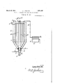
Figure 1 is a vertical section of the apparatus' by which the several steps of the method are carried out, showing "a tank and concentric arrangement of j ackets, and
v Figure 2 is a vertical section of a modified form of tank with the steam jacket omitted.
Continuing with a more detailed explanation of the drawings, 1 designates a cylindrical tank constructed so as to define a substantially funnel shaped lower portion. A.
steam heating jacket 2 and a fuel heating jacket 3 surround the tank 1 in concentric relationship.
In continuing further, it is pointed out that two forms of apparatus are illustrated. While there is but slight difference in the construction and operation of the two modified forms of apparatus, the type illustrated in Figure 2 is preferred, it being understood that the filter, which will be described in detail presently, is substantially the same on Figure 2 as is illustrated in Figure 1.
Certain acid treated clays are mixed with the diluted or contaminated oils placed in the tank 1 and which have the efl'ect of absorbing the impurities, such as dirt, carbon and the like from the oil. The mixture, that is the clay and oil is injected into the tank through the filler opening 4, which has a suitable cover or cap as shown in the drawings. A suitable pressure gauge 5 is provided for the tank and a discharge pipe 6 is disposed at the small end of the funnel shaped lower portion of the tank 1.
It will be noted that the steam heating jacket 2 is likewise funnel shaped so as to embrace the discharge pipe 6 at its lower end. Also surrounding the discharge pipe 6 imniediately below the lower end of the jacket 2 is a burner 7 whereby heat may be applied to the exterior of the said jacket 2 and within the jacket 3 and will emerge through the flue 8 communicating with the top of the exterior jacket 3, as shown in Figure 1 especially.
In the construction shown in Figure 1 lateral pipes 9 are projected through the'tank 1 so as toeifect thorough circulation of heat throughout the contents of the tank. It has been stated that the annular. space between the exterior jacket 3 and the intermediate j acket 2 is heated through the medium of the gas or oil burner 7 surrounding the discharge pipe 6; In order to supply heat into.
the annular area between the jacket 2 and the outer walls of the tank 1, the pipe 10 is provided which is connected to the steam supply tank 11 and introduces steam into the said area and thereby uniformly heatsthe exte- 50 Obviously,
pipes 9, certain of which, as apparent in Figure 1, communicate with the area between the jacket 3 and the Jacket 4, while others communicate with the area between the intermediate jacket 2. Thus, the heat rises from the burner 7 as well as the heat of the steam injected through the pipe 10, as stated.
Due to the circulation of heat from the two sources explained, a topping operation is car- 1'0 ried out, that is to say, the li htervolatile constituents will be converted into vapors Which ascend through the pipe 12, to enter a condenser 13 wherein they will be reduced again to liquid form. Further mention of 15 i the evaporating steps will be made presently.
In order to supply the burner? with fuel, a pipe 14 is provided through which gas or fuel oil may be supplied to theburner, whose heat, as stated preyiously,wi1l rise about the exterior of the jacket 2 and circulate through pressure through a pipe 17, communicating with the discharge pipe 6, into the tank 1, thorough agitation of its contents will be effected, thereby minimizing entrainment of gases in the oil, which would be the case should mechanical agitation be employed.
To aid in the topping or vaporizing step of the process, the oil is heated to a very high degree and maintained s0 throughout the operation.
As apparent in Figure 1, the pipe 6 discharges into an air filter 18, which is provided with a pressure gauge 19. The temperature within this filter is maintained at a high degree of heat by the exhaust of steam. from the steam jacket 3,
which passes through the pipe 20, which communicates with the steam acket near the top of the apparatus and enters the filter 18, in which it is convoluted before its passage therefrom. when the valve 16 in the pipe 6 is actuated to allow the contents of the tank 1 to enter the filter 18, the mixture of oil and clay thus entering the filter will be subjected to the heat radiating from the convoute-d portion of the pipe 20, at approximately 453 F which is a prerequisite for speedy filtration. The valve 16 is not opened until after the topping operation referred to has been completed.
A base flange 21 is provided at the bottom of the filter 18 and which has an annular bead or rib 22 on the underside thereof. A disc 23 is hingedly connected to the flange 21 on one side and is locked diametrically opposite by a bolt 24. The disc 2.3 is perforated and a layer of paper 25 or other suitable ma terial is placed thereon. A layer of fabric 26 is then placed on the layer of paper 25 and a foraminous screen 27 is placed on top of the fabric. It is pointed out'tha-t the oil, the viscosity of which is lowered by the application of heat, filters through laminations of fabric and paper and the perforations in the disc 23.
Filtration of oil through the laminations of fabric and paper is augmented or speeded up by the application of air under pressure through the pipe 28, fragmentarily shown as entering the top of the filter 18 and is connected with any type of conventional air compressor or the like. In thusforcing the oil to filter, it is received within the bowl 29, which is an integral part of the perforated disc or plate 23 and which is provided with an outlet at its bottom, as shown in Figure 1.
After all of the oil has been forced out of the filter 18, the bolt 24 is removed so as to allow the disc 23 to swing downwardly. The layer of paper 25 and the layer of fabric 26, upon which the deposits of clay repose may be ,removed and a new layer substituted for another operation.
The foregoing description being definitive of both structure and function, it is regarded as sufficient to explain the operation of the machine. Also, the description deals with the structure shown in Figure 1, which issub stantially the same as the variation or modified form of the apparatus shown in Figure 2 with the exception of the fact that the heat circulating or distributing pipes 30, shown in Figure 2 are vertically disposed instead of being horizontally disposed as shown in Figure 1. Moreover, the jacket 2 extends above the tank 1 and the filler nozzle 1, must of necessity extend through the upper end of the jacket 2. Otherwise the structure and operation is identical.
Manifestly, the construction shown is capable of some modification and such modification as is considered within the scope and meaning of the appended claims is also considered within the spirit and intent of the invention.
What I claim, is,
1. The hereindescribed process for reclamation of used lubricating oils which resides in introducing the oils, together with acidulated clay in an amount sufficient to restore the oil to its original specification, in a confined zone and heating the mixture to a temperature to drive ofi the more volatile nonlubricating oils without cracking the lubricating oil, then in agitating the mixture solely by passing a continuous stream of air therethrough of such predetermined pressure to effect complete agitation and mixture of the oil and clay and to drive ofl said vapors by said air stream, then as a continuous step drawing off the mixture and filtering the same prior to substantial cooling thereof by super atmospheric air pressure.
2. The hereindescribed process for reclamation of used lubricating oils which resides in introducing the oils, together with acidulated clay in an amount suiiicient to restore the oil to its original specification, in a confined zone and heating the mixture to a temperature to drive ofl the more volatile nonlubricating oils Without cracking the lubri eating oil, then in agitating the mixture solely by passing a continuous stream of air therethroughvof such predetermined pressure to efiect complete agitation and mixture of the oil and clay and to drive 0E said vapors by said air stream, then in drawing 03 the mixture into a separate zone and filtering same at a temperature substantially approximating that of said initial temperature 0 super atmospheric gaseous pressure app 'ed to the surface of the mixture.
In testimony whereof, I set my hand, this 22nd day of August, 1930. LEWIS J. IRELAND.
Priority Applications (1)
| Application Number | Priority Date | Filing Date | Title |
|---|---|---|---|
| US477582A US1851432A (en) | 1930-08-25 | 1930-08-25 | Process of reclamation of crank case or used oils |
Applications Claiming Priority (1)
| Application Number | Priority Date | Filing Date | Title |
|---|---|---|---|
| US477582A US1851432A (en) | 1930-08-25 | 1930-08-25 | Process of reclamation of crank case or used oils |
Publications (1)
| Publication Number | Publication Date |
|---|---|
| US1851432A true US1851432A (en) | 1932-03-29 |
Family
ID=23896524
Family Applications (1)
| Application Number | Title | Priority Date | Filing Date |
|---|---|---|---|
| US477582A Expired - Lifetime US1851432A (en) | 1930-08-25 | 1930-08-25 | Process of reclamation of crank case or used oils |
Country Status (1)
| Country | Link |
|---|---|
| US (1) | US1851432A (en) |
Cited By (1)
| Publication number | Priority date | Publication date | Assignee | Title |
|---|---|---|---|---|
| US2496888A (en) * | 1947-01-22 | 1950-02-07 | De Witt H Palmer | Oil reconditioning or clarifying apparatus |
-
1930
- 1930-08-25 US US477582A patent/US1851432A/en not_active Expired - Lifetime
Cited By (1)
| Publication number | Priority date | Publication date | Assignee | Title |
|---|---|---|---|---|
| US2496888A (en) * | 1947-01-22 | 1950-02-07 | De Witt H Palmer | Oil reconditioning or clarifying apparatus |
Similar Documents
| Publication | Publication Date | Title |
|---|---|---|
| US2342862A (en) | Activated coke | |
| US1447297A (en) | Process for the combined solvent and destructive distillation treatment of oil containing earthy material | |
| US2161964A (en) | Apparatus for treating oil | |
| US1916900A (en) | Method of low temperature distillation | |
| US1851432A (en) | Process of reclamation of crank case or used oils | |
| USRE18898E (en) | Process op reclamation of crank case or used oils | |
| US1823185A (en) | Process of purifying used crank case oil | |
| US2286369A (en) | Method of purifying oil | |
| US2210906A (en) | Oil reclaiming apparatus | |
| US2061666A (en) | Oil purifier | |
| US2045216A (en) | Method of reclaiming used lubricating oil | |
| US2065619A (en) | Oil purification and fractionation and apparatus for same | |
| US1852350A (en) | Apparatus for reclaiming used and diluted lubricating oils | |
| US2332215A (en) | Distillation apparatus | |
| USRE19646E (en) | ireland | |
| US1601727A (en) | Process and apparatus for cracking hydrocarbon oils | |
| US2419579A (en) | Apparatus for re-refining lubricating oil | |
| US1849654A (en) | Method of reclaiming used lubricating oils | |
| US1375245A (en) | Process of distilling hydrocarbons | |
| US1520493A (en) | Revivifying fuller's earth | |
| US1599777A (en) | Process of treating oil | |
| US1453479A (en) | Process of treating hydrocarbon oils | |
| US1917895A (en) | Method and apparatus for condensing and purifying vapors and gases | |
| US1647026A (en) | Process for destructive distillation of hydrocarbons | |
| US1971379A (en) | Method of and apparatus for mixing oils |