US1851425A - Air cooled grate - Google Patents
Air cooled grate Download PDFInfo
- Publication number
- US1851425A US1851425A US343657A US34365729A US1851425A US 1851425 A US1851425 A US 1851425A US 343657 A US343657 A US 343657A US 34365729 A US34365729 A US 34365729A US 1851425 A US1851425 A US 1851425A
- Authority
- US
- United States
- Prior art keywords
- grate
- fins
- plane
- bars
- coal
- Prior art date
- Legal status (The legal status is an assumption and is not a legal conclusion. Google has not performed a legal analysis and makes no representation as to the accuracy of the status listed.)
- Expired - Lifetime
Links
- 239000003245 coal Substances 0.000 description 16
- 239000002184 metal Substances 0.000 description 9
- 241000219051 Fagopyrum Species 0.000 description 7
- 235000009419 Fagopyrum esculentum Nutrition 0.000 description 7
- 239000002956 ash Substances 0.000 description 6
- 235000002918 Fraxinus excelsior Nutrition 0.000 description 4
- 239000000446 fuel Substances 0.000 description 4
- 238000002485 combustion reaction Methods 0.000 description 2
- 230000003247 decreasing effect Effects 0.000 description 2
- 239000000463 material Substances 0.000 description 2
- QEIQEORTEYHSJH-UHFFFAOYSA-N Armin Natural products C1=CC(=O)OC2=C(O)C(OCC(CCO)C)=CC=C21 QEIQEORTEYHSJH-UHFFFAOYSA-N 0.000 description 1
- 241000196324 Embryophyta Species 0.000 description 1
- 238000001816 cooling Methods 0.000 description 1
- 239000010419 fine particle Substances 0.000 description 1
- 230000003137 locomotive effect Effects 0.000 description 1
- 229920000136 polysorbate Polymers 0.000 description 1
- 230000005855 radiation Effects 0.000 description 1
- 241000894007 species Species 0.000 description 1
Images
Classifications
-
- F—MECHANICAL ENGINEERING; LIGHTING; HEATING; WEAPONS; BLASTING
- F23—COMBUSTION APPARATUS; COMBUSTION PROCESSES
- F23H—GRATES; CLEANING OR RAKING GRATES
- F23H13/00—Grates not covered by any of groups F23H1/00-F23H11/00
-
- F—MECHANICAL ENGINEERING; LIGHTING; HEATING; WEAPONS; BLASTING
- F23—COMBUSTION APPARATUS; COMBUSTION PROCESSES
- F23H—GRATES; CLEANING OR RAKING GRATES
- F23H2700/00—Grates characterised by special features or applications
- F23H2700/001—Grates specially adapted for steam boilers
Definitions
- ATTORNEY A forced draft may be used if Patented maze, 1932 ANDREW GAUL, .13., or Armin; new YORK AIR coonnn i-RATE Application filedltarch 1,
- My invention relates to grates for burning coaland particularly to grates for burning very fine coal, such as No. 1 buckwheat and smaller, without a forced draft, although desired.
- Grates of the ordinary type used for burning coal in larger sizes are not adapted for burning coal of the buckwheat and smaller sizes because the spacing between the, grate 10 bars is so great that the finer coaldrops through into the ash pit.
- the spacing of the grate bars is decreased so that the coaldoes not fall through, the available space for the passage of air is cut down to such an extent that the 'coal cannot be burned without a forced draft.
- both the spacing and thickness of bars of the present types are reduced, the grate, because of its comparatively delicate structure burns and warps unless kept cool by some forced draft.
- One of the objects of my invention is to provide a grate which will satisfactorily and economically burn the finer sizes of coalwithout a forced draft and with a chimney of ordinary residential height.
- Another I character that when used with forced draft or induced draft such as in a locomotive, steam vessel or industrial plant, these finer sizes of coal may be burned at a much higher rate than is now possible with present type grates.
- Another ObJGOt'lS to provide a grateof this character having substantially no surfaces upon or between which ashes may accumulate.
- Another incidental object is to provide a grate for a furnace having a circular fire pot in which there will be no openings of such a,
- Another object is to provide a grate having a minimum amount of metal therein and having this object is to provide a grate of such 1929.
- Another object is to provide a grate which, while particularly adapted to burn extremely fine coal, is also adapted to burn coal of any size and may be shaken or turned in such a way as to. provide openings sufliciently large for the passage of any stones, clinkers or ,cind'ers present in the fire pot. And a further object is to .pro-
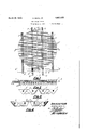
- Fig. 1 is a plan view of my grate adapted for a furnace having a round fire box
- Fig. 2 is a section of Fig. 1 inthe plane 2-
- Fi 3 is a section of Fig. 1 in the plane 3-3
- 4 is a section ofFig. 1 in the plane 9
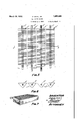
- Fig. 5 illustrates my grate as adapted for a furnace having a rectangular fire box;
- Fig. 6 is a section of Fig. 5 in the plane 66;
- Fig. 7 is a fragmentary perspective view of a section of a stationary grate.
- my grate when circular or square, prefera ly comprises four sections carried by the supporting bars, 1, 2,
- these fins are space occupied by the fins
- the fins should in all instances, be very thin at the top, for example, not over one-fourth inch, and preferably one-eighth of an inch or slightly less in thickness, and the clear spaces between the bars, at the top, should always be substantially wider than the thickness of the bars thus assuring a ratio of. air space to metal in excess of 1 to 1.
- buckwheat for example, is to be burned, it has been found in practice that fins oneeighth of an'inch thick at the top and spaced as wide as five-sixteenth of an inch will give highly satisfactory results.
- the spaces between the fins at the bottom are about seven-sixteenths of an inch'so that ashes passing the spaces through when the grate is agitated and will not become clogged between the fins.
- each element of the grate as well as the fins may be alike, as shown in Fig. 5.
- each one of the grate elements is necessarily different.
- the outer edges of the fins associated with supporting bars, 1 and 4 are arranged in a circular areas are also the edges of several of the fins at each end of bars, 2 and 3.
- the extreme fins at each end of the supporting bars, 2 and 3 are provided with projections, 7, disposed at right angles to the end fins so that no large space remains here between the grate and fire pot.
- the spaces, 6, between the separate sections of the grate should, of course, conform substantially to the spacing of the fins.
- grates consist of four separate, as shown in Figs. 1 and 5, the usual gear wheels, 8 and 9, which mesh toand 10 and 11, which mesh together, are provided on the front ends of the supporting bars. Bars, 2 and 3, are also squared at the ends, as shown at 12, to receive a shaker handle.
- the particular configuration of the fins is able grate not important but where a grate of the rocking type is to be provided, the fins, below the plane of the fire, must be of such shape as to provide the necessary clearance in dumping or shaking. For this reason, and because it is preferred to .keep the metal content as low as possible, the best form of fin is believed to be approximately triangular and about in the proportions shown. 1
- the fins By making the fins extremely thin, and thinner than the spaces between, it is possible to provide a grate having an unusually large air surface as compared to the metal surface in the plane of the top of the grate.
- the grates are made to the dimensions mentioned above as suitable for burning No. 1 buckwheat, the air surface is practically 75% of total grate surface and the metal area is only 25%. In other words, there is three times as much air as metal. This makes it quite possible to burn very fine coal with the natural draft available in the chimney of the ordinary dwelling.
- the extremely high radiation from the fins serves to preheat the air fed to the fire and some increased efliciency in combustion is attained in this way.
- a grate for burning coal of the finer sizes, such as buckwheat, without material loss by falling through comprisin a plurality of parallel, very thin but deep s having theirmaximum thickness at the topto form a supporting surface for the fuel, and characterized by having said fins closely spaced in the plane of the top but having the thickness of said fins in said plane less than the space between said fins in said plane whereby the minimum aggregate cross sectional area of the air spaces substantially exceeds the maximum aggregate cross sectional area of metal throughout the grate.
- a grate for burning coal of the finer sizes, such as buckwheat, without material loss by falling through comprising a plurality of parallel bars provided with very thin but deep transverse fins having their maximum thickness at the top to form a supporting surface for the fuel, and characterized by having said fins closely spaced in the plane of the top but having t e thickness of said fins in said plane 'less than the space be- I tween said fins in said plane whereby the minimum aggregate cross sectional.
- grate being rocked; and said grate being characterized by having said fins closely spaced in the plane of the top but having the thickness of said fins in said plane less than the space between said fins in said plane; whereby the minimum aggregate cross'sectional area of air spaces substantially exceeds the maximum aggregate cross sectional area of metal throughout the grate.
- grate for burning coal of the finer sizes, such as buckwheat, without material loss' by falling through comprising a plurality of parallel bars provided with very thin but deep transverse fins cast integral therewith and having their maximum thickness at the top to form a supporting surface for the fuel, and characterized by having said fins closely spaced in the plane of the top but having the thickness of said fins in said plane less than the space between said fins in said plane whereby the minimum aggregate cross a sectional area of air spaces substantially exceeds the maximum aggregate cross sectional area of metal throughout the grate.
- a rocking grate for burning coal of the finer sizes, such asbuckwheat, without substantial loss b falling through comprising a plurality o rotatably mounted, parallel, supporting bars provided with a multiplicity of very thin but deep transverse fins decreasing both in width and thickness from a maximum at the top and forming a supporting surface for the fuel; said fins havin comparatively sharp, knife-like edges w ereby clinkers arecut and broken up when the
Landscapes
- Engineering & Computer Science (AREA)
- Chemical & Material Sciences (AREA)
- Combustion & Propulsion (AREA)
- Mechanical Engineering (AREA)
- General Engineering & Computer Science (AREA)
- Solid-Fuel Combustion (AREA)
Description
March 29, 1932. A, U JR 1,851,425
AIR COOLED GRATE Filed March 1, 1929 2 Sheets-Sheet 1v //VVENTOR Andrew 640/, Jr.
' /47TORNEY March 29, 1932. A. GAUL. JR
AIR COOLED GRATE 2 Sheets-Sheet 2 Filed March 1, 1929 Hlil II I
ATTORNEY A a forced draft may be used if Patented maze, 1932 ANDREW GAUL, .13., or Armin; new YORK AIR coonnn i-RATE Application filedltarch 1,
My invention relates to grates for burning coaland particularly to grates for burning very fine coal, such as No. 1 buckwheat and smaller, without a forced draft, although desired.
, Grates of the ordinary type used for burning coal in larger sizes are not adapted for burning coal of the buckwheat and smaller sizes because the spacing between the, grate 10 bars is so great that the finer coaldrops through into the ash pit. When the spacing of the grate bars is decreased so that the coaldoes not fall through, the available space for the passage of air is cut down to such an extent that the 'coal cannot be burned without a forced draft. \Vhen both the spacing and thickness of bars of the present types are reduced, the grate, because of its comparatively delicate structure burns and warps unless kept cool by some forced draft. For these reasons, it has not been practicable to burn buckwheat or finer coal with a natural draft in residences having chimneys ofordinary height. Furthermore, the maximum volume of air which it is possible to pass through grates of the present type adapted for burning the finer sizes of coal is insuflicient to provide the high rate of combustion which,
in many instances, is desired.
One of the objects of my invention, therefore, is to provide a grate which will satisfactorily and economically burn the finer sizes of coalwithout a forced draft and with a chimney of ordinary residential height. Another I character that when used with forced draft or induced draft such as in a locomotive, steam vessel or industrial plant, these finer sizes of coal may be burned at a much higher rate than is now possible with present type grates. Another ObJGOt'lS to provide a grateof this character having substantially no surfaces upon or between which ashes may accumulate. Another incidental object is to provide a grate for a furnace having a circular fire pot in which there will be no openings of such a,
large size that fine particles of coal can fall therethrough into the ash .pit. Another object is to provide a grate having a minimum amount of metal therein and having this object is to provide a grate of such 1929. Serial N0. 343,657.
.of'the type now used. Another object is to provide a grate which, while particularly adapted to burn extremely fine coal, is also adapted to burn coal of any size and may be shaken or turned in such a way as to. provide openings sufliciently large for the passage of any stones, clinkers or ,cind'ers present in the fire pot. And a further object is to .pro-
vide a grate throu h volume of air may than with grates of the present type.
I accomplish these objects by the means and in the manner described in the following which a much greater e passed in a. given time specification and illustrated in the accompan'ying drawings in which- -ig. 1 is a plan view of my grate adapted for a furnace having a round fire box Fig. 2 is a section of Fig. 1 inthe plane 2- Fi 3 is a section of Fig. 1 in the plane 3-3 1 4 is a section ofFig. 1 in the plane 9 I Fig. 5 illustrates my grate as adapted for a furnace having a rectangular fire box;
Fig. 6 is a section of Fig. 5 in the plane 66; and
Fig. 7 is a fragmentary perspective view of a section of a stationary grate. Referring to the drawings, my grate, when circular or square, prefera ly comprises four sections carried by the supporting bars, 1, 2,
3 and- 4, and assembled upon which, or preferably cast integral therewith, are the fins represented generally in Figs. 1, 2, 3 and 4, by the numeral, 5. and'in Figs. 5 and 6 by the numeral, 5'.. -Where the grates are to be used with a furnace having a rectangular fire box, all of the fins may be similar, as
shown in Figs, 5 and 6. In either the round or rectangular species of grate, these fins are space occupied by the fins,
extremely thin plates of metal, and preferably but not necessarily decrease in thickness from the top to a comparatively sharp edge having no substantial thickness at the bottom. Thefins in any case are comparatively deep so that the sides of each present heat radiating surfaces of substantial area to the incoming air. The supporting bars are of course round where they pass through the sides of the fire box so that they may be turned in shaking, but the cross section, within the is preferably quite steeply sloped upon the top as shown in Figs. 3 and 6 so that ashes will not rest thereon. It will also be noted that the bars 1, 2, 3 and 4, and the bars, 1, 2, 3 and 4. are spaced at the top will readily fall somewhat below the upper edges of the fins.
The fins should in all instances, be very thin at the top, for example, not over one-fourth inch, and preferably one-eighth of an inch or slightly less in thickness, and the clear spaces between the bars, at the top, should always be substantially wider than the thickness of the bars thus assuring a ratio of. air space to metal in excess of 1 to 1. Where-No. 1 buckwheat, for example, is to be burned, it has been found in practice that fins oneeighth of an'inch thick at the top and spaced as wide as five-sixteenth of an inch will give highly satisfactory results. In this case, if the fins are tapered the spaces between the fins at the bottom are about seven-sixteenths of an inch'so that ashes passing the spaces through when the grate is agitated and will not become clogged between the fins.
main elements,
- gether,
Where the grate is intended for use with a furnace having a rectangular fire box there may be as many separate elements as are necessary, and each element of the grate as well as the fins may be alike, as shown in Fig. 5. Where the grate is intended for use in a circular fire box each one of the grate elements is necessarily different. In the latter case, the outer edges of the fins associated with supporting bars, 1 and 4, are arranged in a circular areas are also the edges of several of the fins at each end of bars, 2 and 3. As shown in Figs. 1, 2 and 4, the extreme fins at each end of the supporting bars, 2 and 3, are provided with projections, 7, disposed at right angles to the end fins so that no large space remains here between the grate and fire pot. The spaces, 6, between the separate sections of the grate should, of course, conform substantially to the spacing of the fins.
Where the grates consist of four separate, as shown in Figs. 1 and 5, the usual gear wheels, 8 and 9, which mesh toand 10 and 11, which mesh together, are provided on the front ends of the supporting bars. Bars, 2 and 3, are also squared at the ends, as shown at 12, to receive a shaker handle.
The particular configuration of the fins is able grate not important but where a grate of the rocking type is to be provided, the fins, below the plane of the fire, must be of such shape as to provide the necessary clearance in dumping or shaking. For this reason, and because it is preferred to .keep the metal content as low as possible, the best form of fin is believed to be approximately triangular and about in the proportions shown. 1
By making the fins extremely thin, and thinner than the spaces between, it is possible to provide a grate having an unusually large air surface as compared to the metal surface in the plane of the top of the grate. \Vhere the grates are made to the dimensions mentioned above as suitable for burning No. 1 buckwheat, the air surface is practically 75% of total grate surface and the metal area is only 25%. In other words, there is three times as much air as metal. This makes it quite possible to burn very fine coal with the natural draft available in the chimney of the ordinary dwelling. Furthermore, the extremely high radiation from the fins serves to preheat the air fed to the fire and some increased efliciency in combustion is attained in this way.
By making the fins extremely thin and very deep to provide large heat-radiating or cooling surfaces, all warping or burning of the grate is avoided, and although such a grate is rather delicate in appearance it is, 011 account of its relatively great depth, in fact extremely durable and serviceable.
By-gearing the supporting bars together, as illustrated, it is obviously possible to move the grate elements so that comparatively large spaces are opened between them. It will be apparent, therefore, that such a grate is in nowise limited to burning a fine size of coal, and while particularly adapted for the smaller sizes of coal may be used with any fuel of any size.
In many instances Where the ashes are removed by raking instead of shaking a movis not essential. In such cases a design similar to that shown in Fig. 7 may be used. Here, atively long and substantially rectangular when viewed from the side. They are preferably tapered to substantially no thickness at the bottom and are made deep enough to withstand the vertical load thereon when considered as beams, as well as to provide large the bars or fins are comparpreferred embodiment it is to be understood that the illustrations are typical only and that the words which I have used are words of description rather than of limitation, and that changes, within the purview of the appended claims, may be made without departing from the true scope and spirit of my invention in its broad aspects.
What I claim is l. A grate for burning coal of the finer sizes, such as buckwheat, without material loss by falling through, comprisin a plurality of parallel, very thin but deep s having theirmaximum thickness at the topto form a supporting surface for the fuel, and characterized by having said fins closely spaced in the plane of the top but having the thickness of said fins in said plane less than the space between said fins in said plane whereby the minimum aggregate cross sectional area of the air spaces substantially exceeds the maximum aggregate cross sectional area of metal throughout the grate.
2. A grate for burning coal of the finer sizes, such as buckwheat, without material loss by falling through, comprising a plurality of parallel bars provided with very thin but deep transverse fins having their maximum thickness at the top to form a supporting surface for the fuel, and characterized by having said fins closely spaced in the plane of the top but having t e thickness of said fins in said plane 'less than the space be- I tween said fins in said plane whereby the minimum aggregate cross sectional. area of grate is rocked; and said grate being characterized by having said fins closely spaced in the plane of the top but having the thickness of said fins in said plane less than the space between said fins in said plane; whereby the minimum aggregate cross'sectional area of air spaces substantially exceeds the maximum aggregate cross sectional area of metal throughout the grate.
ANDREW GAUL, JR-
air spaces substantially exceeds the maximum aggregate'cross sectional area of metal throughout the grate.
3. grate for burning coal of the finer sizes, such as buckwheat, without material loss' by falling through, comprising a plurality of parallel bars provided with very thin but deep transverse fins cast integral therewith and having their maximum thickness at the top to form a supporting surface for the fuel, and characterized by having said fins closely spaced in the plane of the top but having the thickness of said fins in said plane less than the space between said fins in said plane whereby the minimum aggregate cross a sectional area of air spaces substantially exceeds the maximum aggregate cross sectional area of metal throughout the grate.
.4. A rocking grate for burning coal of the finer sizes, such asbuckwheat, without substantial loss b falling through, comprising a plurality o rotatably mounted, parallel, supporting bars provided with a multiplicity of very thin but deep transverse fins decreasing both in width and thickness from a maximum at the top and forming a supporting surface for the fuel; said fins havin comparatively sharp, knife-like edges w ereby clinkers arecut and broken up when the
Priority Applications (1)
| Application Number | Priority Date | Filing Date | Title |
|---|---|---|---|
| US343657A US1851425A (en) | 1929-03-01 | 1929-03-01 | Air cooled grate |
Applications Claiming Priority (1)
| Application Number | Priority Date | Filing Date | Title |
|---|---|---|---|
| US343657A US1851425A (en) | 1929-03-01 | 1929-03-01 | Air cooled grate |
Publications (1)
| Publication Number | Publication Date |
|---|---|
| US1851425A true US1851425A (en) | 1932-03-29 |
Family
ID=23347031
Family Applications (1)
| Application Number | Title | Priority Date | Filing Date |
|---|---|---|---|
| US343657A Expired - Lifetime US1851425A (en) | 1929-03-01 | 1929-03-01 | Air cooled grate |
Country Status (1)
| Country | Link |
|---|---|
| US (1) | US1851425A (en) |
-
1929
- 1929-03-01 US US343657A patent/US1851425A/en not_active Expired - Lifetime
Similar Documents
| Publication | Publication Date | Title |
|---|---|---|
| US1851425A (en) | Air cooled grate | |
| US277754A (en) | Territoby | |
| US1974143A (en) | Furnace | |
| US1397386A (en) | hqessieb | |
| US242964A (en) | nikiforoff | |
| US2016869A (en) | Fire grate | |
| US709377A (en) | Grate. | |
| US1959117A (en) | Grate construction | |
| US1742081A (en) | Furnace grate | |
| US529504A (en) | Grate | |
| US2038805A (en) | Grate | |
| US780888A (en) | Grate. | |
| US972965A (en) | Grate-bar. | |
| SU2196A1 (en) | Grate for oil burning | |
| US400824A (en) | Furnace-grate for portable engines | |
| USRE6407E (en) | Improvement in grates | |
| US192073A (en) | Improvement in furnace-grates | |
| US1591568A (en) | Grate | |
| US602933A (en) | Richard bowes | |
| US1232897A (en) | Grate for marine and stationary boilers. | |
| US1920817A (en) | Fire box construction | |
| US1861015A (en) | Shaking grate for furnaces | |
| US535984A (en) | Agitating fire-grate | |
| US402842A (en) | Grate | |
| US1613316A (en) | Chain grate |