US1851397A - Gear shaping mechanism - Google Patents
Gear shaping mechanism Download PDFInfo
- Publication number
- US1851397A US1851397A US507086A US50708631A US1851397A US 1851397 A US1851397 A US 1851397A US 507086 A US507086 A US 507086A US 50708631 A US50708631 A US 50708631A US 1851397 A US1851397 A US 1851397A
- Authority
- US
- United States
- Prior art keywords
- sector
- teeth
- gear shaping
- shaping mechanism
- shaping
- Prior art date
- Legal status (The legal status is an assumption and is not a legal conclusion. Google has not performed a legal analysis and makes no representation as to the accuracy of the status listed.)
- Expired - Lifetime
Links
- 238000010862 gear shaping Methods 0.000 title description 3
- 238000010791 quenching Methods 0.000 description 5
- 230000000171 quenching effect Effects 0.000 description 4
- 238000007493 shaping process Methods 0.000 description 4
- 238000005520 cutting process Methods 0.000 description 3
- 238000003754 machining Methods 0.000 description 2
- 230000004075 alteration Effects 0.000 description 1
- 238000004519 manufacturing process Methods 0.000 description 1
- 238000000034 method Methods 0.000 description 1
Images
Classifications
-
- B—PERFORMING OPERATIONS; TRANSPORTING
- B21—MECHANICAL METAL-WORKING WITHOUT ESSENTIALLY REMOVING MATERIAL; PUNCHING METAL
- B21K—MAKING FORGED OR PRESSED METAL PRODUCTS, e.g. HORSE-SHOES, RIVETS, BOLTS OR WHEELS
- B21K1/00—Making machine elements
- B21K1/28—Making machine elements wheels; discs
- B21K1/30—Making machine elements wheels; discs with gear-teeth
- B21K1/305—Making machine elements wheels; discs with gear-teeth helical
Definitions
- the present invention relates to steering mechanism and embodles, more specifically,
- An object of the present invention is to provide an apparatus forobtaining relief at r the ends of steering sectors and the like, the
- a further object of the invention is to .pro-
- a further object of the invention is to provide an apparatus for obtaining relief at the ends of sectors by forming the same in a desired fashion after the teeth have been cut.
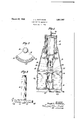
- Figure 1 is a sectional view in elevation, showing a quenching press which is adapted therebetween in a desired manner as the sector is submerged in the oil 24.
- Flgure 2 is aview in end elevation show-" ing a sector formed in accordance with the present nventlon.
- F-i ur'e 31s a view in side'elevation, showing the'sect'or of Figure 2.
- the ends 13 of the sector thus lie below the high point'12 and cause the teeth at the highpoint to engage the worm more closely than the teeth adjacent the low points 13.
- the sector is formed in'the manner described hereinafter, this, step being done any time after cutting whether the sector is hot or cold.
- the shaping is preferably done at the time of final quenching for hardening the piece and may be done in a press comprising a frame 14 supporting cylindersv 15 and 16.
- a piston 17 is slidably mounted within cylinder 15, while piston 18 is carried the cylinder 16.
- a die 19 is carried, this die being adapted to receive the sector shaft and, on its lower face, being curved, as at 20 to shape the sector suitably during quenching.
- Piston 18 carries a cooperating die 21 which is formed with a curved surface 22 similar to the surface 20.
- Pipes 23 may supply com-' pressed airto the respective cylinders and actuate the dies to shape the sector received The shaping process does not add to the manufacturing operations required in making the 7 it add materially to the expense of such operations, since the standard equipment now available may be usedwith only the' slight alteration of changing the dies-of the press.
- a device for forming gear sectors in .desired shapes comprising a receptacle adapted to receive alquenching vloath, a pressure member carried thereby and movable into the bath, v
Landscapes
- Engineering & Computer Science (AREA)
- Mechanical Engineering (AREA)
- Gears, Cams (AREA)
Description
March 29, 1932. M 1,851,397
GEAR SHAPING MECHANISM 1 Fil ed Jan. '7, 1951 INVENTOR Jamey/1 LMa/Memv,
Patented Mar. 29, 1932 UNITED STATES PATENT "WE JOSEPH L. MATTHEWS, on NEW BRUNSWICK, .NEW JERSEY, AssIe noarro I TER NATIONAL MOTOR COMIEANY, OF NEW YOBK,. N.
GEAR SHAPING EMECH-ANISM Application filed. January}, i931. Serial 507,086. I
The present invention relates to steering mechanism and embodles, more specifically,
an improved method of forming steering gear thereof than at the ends of the sector and to compensate for this condition, it has been usual in standard sectors (of the helical worm type) to machine the teeth eccentric to the axis thus producing a high point in the center of the sector and low points adjacent the ends thereof. In this fashion, the teeth of the central part of the sector may be kept closely in mesh with the worm by means of adjustment, even after the central teeth become worn,
"" without danger of binding or tightness at the ends of the sector. With sectors of the side worm type, it is difficult to obtain relief at the ends of the sector during machining since the provision of the above described eccentricity requires extremely difficult machining operations.
' An object of the present invention is to provide an apparatus forobtaining relief at r the ends of steering sectors and the like, the
desired shape of the sector being perfected after the teeth have been cut. 1
A further object of the invention is to .pro-
vide an apparatus of the above character, wherein the shaping and quenching operations may be effected simultaneously.
A further object of the invention is to provide an apparatus for obtaining relief at the ends of sectors by forming the same in a desired fashion after the teeth have been cut.
Further objects, not specifically enumerated above, will be apparent as the invention is described in greater detail in connection with the accompanyingdrawings, wherein Figure 1 is a sectional view in elevation, showing a quenching press which is adapted therebetween in a desired manner as the sector is submerged in the oil 24.
surface nor does A CORPORATION or DELAWARE to quench and shape an object simultaneously, Flgure 2 is aview in end elevation show-" ing a sector formed in accordance with the present nventlon.
F-i ur'e 31s a view in side'elevation, showing the'sect'or of Figure 2.
Referring to the above drawlngs, part1cularlyto Figures 2 and 3, itwill be seen that the sector shaft 10 carries a sector 11, the
plane of the teeth of which has been formed to slope away from a central or intermediate high point 12.. v This plane is indicated by the line A in Figure 3 and the plane of cutting, prior to shaping, is indicated by the line B.
The ends 13 of the sector thus lie below the high point'12 and cause the teeth at the highpoint to engage the worm more closely than the teeth adjacent the low points 13.
After the cutting of the teeth in the normal plane B, the sector is formed in'the manner described hereinafter, this, step being done any time after cutting whether the sector is hot or cold. The shaping is preferably done at the time of final quenching for hardening the piece and may be done in a press comprising a frame 14 supporting cylindersv 15 and 16. A piston 17 is slidably mounted within cylinder 15, while piston 18 is carried the cylinder 16. At the lower end of pisy ton 17, a die 19 is carried, this die being adapted to receive the sector shaft and, on its lower face, being curved, as at 20 to shape the sector suitably during quenching.
Piston 18 carries a cooperating die 21 which is formed with a curved surface 22 similar to the surface 20. Pipes 23 may supply com-' pressed airto the respective cylinders and actuate the dies to shape the sector received The shaping process does not add to the manufacturing operations required in making the 7 it add materially to the expense of such operations, since the standard equipment now available may be usedwith only the' slight alteration of changing the dies-of the press.
While the invention has been described with specific reference to the accompanying drawings, it is not to be limited, save as defined in the appended claim.
I claim asmy invention:
A device for forming gear sectors in .desired shapes comprising a receptacle adapted to receive alquenching vloath, a pressure member carried thereby and movable into the bath, v
a cooperating pressure member. coaxial with the first member and movable with respect thereto, and pressure plates carried by the members and having pressure surfaces each converging to a high point intermediate the endsthereof. y v v This specification signed this 3 1 day of December, A. D. 1930. v v
, I .VJOSEPHIL. MATTHEWS.
Priority Applications (2)
| Application Number | Priority Date | Filing Date | Title |
|---|---|---|---|
| US507086A US1851397A (en) | 1931-01-07 | 1931-01-07 | Gear shaping mechanism |
| US556370A US1902656A (en) | 1931-01-07 | 1931-08-11 | Method of manufacturing gearing |
Applications Claiming Priority (1)
| Application Number | Priority Date | Filing Date | Title |
|---|---|---|---|
| US507086A US1851397A (en) | 1931-01-07 | 1931-01-07 | Gear shaping mechanism |
Publications (1)
| Publication Number | Publication Date |
|---|---|
| US1851397A true US1851397A (en) | 1932-03-29 |
Family
ID=24017193
Family Applications (1)
| Application Number | Title | Priority Date | Filing Date |
|---|---|---|---|
| US507086A Expired - Lifetime US1851397A (en) | 1931-01-07 | 1931-01-07 | Gear shaping mechanism |
Country Status (1)
| Country | Link |
|---|---|
| US (1) | US1851397A (en) |
Cited By (3)
| Publication number | Priority date | Publication date | Assignee | Title |
|---|---|---|---|---|
| US2458587A (en) * | 1945-01-31 | 1949-01-11 | Gogan Joseph | Apparatus for treating hollow bodies |
| US2467665A (en) * | 1945-01-31 | 1949-04-19 | Gogan Joseph | Straightening and quenching apparatus with contracting dies and auxiliary loading platform |
| US2699412A (en) * | 1949-10-22 | 1955-01-11 | Gleason Works | Pinion quenching machine and process |
-
1931
- 1931-01-07 US US507086A patent/US1851397A/en not_active Expired - Lifetime
Cited By (3)
| Publication number | Priority date | Publication date | Assignee | Title |
|---|---|---|---|---|
| US2458587A (en) * | 1945-01-31 | 1949-01-11 | Gogan Joseph | Apparatus for treating hollow bodies |
| US2467665A (en) * | 1945-01-31 | 1949-04-19 | Gogan Joseph | Straightening and quenching apparatus with contracting dies and auxiliary loading platform |
| US2699412A (en) * | 1949-10-22 | 1955-01-11 | Gleason Works | Pinion quenching machine and process |
Similar Documents
| Publication | Publication Date | Title |
|---|---|---|
| US1851397A (en) | Gear shaping mechanism | |
| US3780413A (en) | Method for making hollow bevel gears with integral hollow shaft | |
| CN109175175B (en) | Precise hot-working forming method for automobile steering ball joint | |
| JP5246588B2 (en) | Gear manufacturing apparatus and method | |
| US2040957A (en) | Metalworking process | |
| US3828628A (en) | Methods of extruding helical gear blanks | |
| ES373560A1 (en) | Method of producing moulds consisting of metal tubes for continuous casting machines | |
| US1902656A (en) | Method of manufacturing gearing | |
| US2788831A (en) | Apparatus for straightening metallic vehicle bumpers | |
| US1444270A (en) | Process of manufacture of rough pieces for brass tubes | |
| US1493516A (en) | Swaging press | |
| US2193661A (en) | Washer and method of making | |
| US1572303A (en) | Method of forming internal keys on tubes | |
| DE926482C (en) | Process for the production of seamless light metal tubes with collars consisting of one piece | |
| US2061403A (en) | Die | |
| US1933568A (en) | Method of making piston rings | |
| US1733226A (en) | Method of making valve casings | |
| US2244852A (en) | Manufacture of forging blanks | |
| US2790227A (en) | Process of making crank shafts | |
| US1263271A (en) | Process for making metal rings. | |
| SU978997A1 (en) | Forging production method | |
| US1992170A (en) | Apparatus for casting helical objects and the like | |
| US1816298A (en) | Manufacture of hollow sheet metal shapes | |
| DE677931C (en) | Process for the production of centrifugally cast socket shells | |
| US1326205A (en) | Assigstob to the timkest bolleb bbasistg |