US1851375A - Horse hayrake ejector - Google Patents
Horse hayrake ejector Download PDFInfo
- Publication number
- US1851375A US1851375A US467551A US46755130A US1851375A US 1851375 A US1851375 A US 1851375A US 467551 A US467551 A US 467551A US 46755130 A US46755130 A US 46755130A US 1851375 A US1851375 A US 1851375A
- Authority
- US
- United States
- Prior art keywords
- rake
- slide
- prong
- ejector
- attachment
- Prior art date
- Legal status (The legal status is an assumption and is not a legal conclusion. Google has not performed a legal analysis and makes no representation as to the accuracy of the status listed.)
- Expired - Lifetime
Links
- 238000010276 construction Methods 0.000 description 2
- 239000011435 rock Substances 0.000 description 2
- 241000369592 Platycephalus richardsoni Species 0.000 description 1
- 229910000746 Structural steel Inorganic materials 0.000 description 1
- FUHMZYWBSHTEDZ-UHFFFAOYSA-M bispyribac-sodium Chemical compound [Na+].COC1=CC(OC)=NC(OC=2C(=C(OC=3N=C(OC)C=C(OC)N=3)C=CC=2)C([O-])=O)=N1 FUHMZYWBSHTEDZ-UHFFFAOYSA-M 0.000 description 1
- 238000007599 discharging Methods 0.000 description 1
- 230000000694 effects Effects 0.000 description 1
- 230000004048 modification Effects 0.000 description 1
- 238000012986 modification Methods 0.000 description 1
Images
Classifications
-
- A—HUMAN NECESSITIES
- A01—AGRICULTURE; FORESTRY; ANIMAL HUSBANDRY; HUNTING; TRAPPING; FISHING
- A01D—HARVESTING; MOWING
- A01D87/00—Loaders for hay or like field crops
- A01D87/0053—Tractor-mounted loaders
-
- A—HUMAN NECESSITIES
- A01—AGRICULTURE; FORESTRY; ANIMAL HUSBANDRY; HUNTING; TRAPPING; FISHING
- A01D—HARVESTING; MOWING
- A01D85/00—Arrangements for making or setting stacks
- A01D85/001—Arrangements for making or setting stacks making or setting stacks of cereals or grass, e.g. rack formers, fixed haystacks
Definitions
- This, invention relates "to means for automafia-ally removing hay,- str-aw and the like 7 from mechanically propelledrakes, and profvides an ejector attachment adapted to be @readily applied to any type and make of rake Without requiring any change or modification inthe construction thereof, or the services of 'a'skilled mechanic, a
- the attachment contemplates and mcludes .10. a slide, a head at the rear end of the slide, a
- the attachment derstood that in adapting the means to meet v specific needsjand requirements, the design may be varied and changes in the minor details of construction may be resorted to Within the scope of the invention as claimed without departingfrom the spirit thereof.
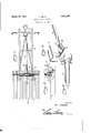
- Figure 1 is atop plan view of a horse hay rake of conventional form provided with hay ejecting means embodyingthe inven- Figure 2 is a longitudinal'sectional view
- Figure 3 is afragnientary perspectivelview of parts of-the 'slideand prong, showing the means pivotally connecting the prong to the slide.
- i 4 5 r 'Fignre- 4: is a detailsectional view of the which the attachmentis mounted, v p
- f9 andthepro-ng 6 is pivotally connected to the Plate '1'0 by means of bolt :11; It will slide and a part of the head attachedthereto and showing a portion of a rake. tooth upon to in the following description and designat" head 2, and draft frame3, to which a team of Q ses isadapted to beh-itched inthe'accusf: 'tomed-inanner. i 1
- the hay ejecting attachment comprises "a i f slideid, "head 5 at-therearenddf theslide,
- the slide 4 iselo'ngated and channeled -in its bottom side to embracethe top and opposite sidesof a rake toothi.
- This side pref s50 erably consists of a length of channel iron or may be fformed from a metalplate bent
- AboltQ connects the 'sidepieces of the slide l'adjacent their rearends and extendsacross the bottom-side of the @tooth l to prevent vertical displacemento'f the slide.
- the attachment may "be, applied to a rake "by slipping it upon the middle tooth' so that 1 'the ⁇ roller 8 Y rests upon the top; of the tooth and thefbolt'g) extendsiacross the bottomside of theto'oth.
- the -rake By having the prong ;6*piVQ?tall;y an; connected to the slide 4 i-n-the manner ind-i- ;cated,the -rake may beturned in either :direction ⁇ preliminary to :recrossing thefield after dl-schargingtheload
- the attachment is ra'u- .tomatic in actionandimaybe, readily applied to and quickly removed from a rake, as will be readily appreciated.
- a bar 12 is pivoted to the head 5, at 13, and
- This bar rests upon a cross piece 14 and normally inclines upwardly and rearwardly.
- the driver or attendant may push the ejector forward by pressing upon the bar 12 which, when it clears the cross piece 1 1, drops in front thereof and rests upon a trip 15 which is pivoted on the cross piece.
- This trip is substantially U-shaped and its members are of different len hs, the shortmember 16 engaging under the ar 12 and'the long member having a cord 17 connected thereto and extending within convenient reachof the driversseat 18.
- An attachment for a horse hay rake comprising a slide to fit upon atooth of the rake, a head carried by the slide, a bar pivoted to the head and extending rearwardly therefrom, a stop on the rake to be engaged by the pivoted bar and hold said bar pressed forward, and a trip on the rake operable from the drivers seat to efiect release of the pivoted bar from the said stop.
- FRANCIS SMITH said means consisting of a slide mounted upona tooth of the rake, a head at therear end of the slide normally in front of the head of the rake, a prong pivoted to the slide and adapted to move freely over the ground during the forward movement of the rake and to penetrate the ground below the rake and hold the slide stationary when the rake is moved rearward, and a'check connecting the prong and the rake to limit the forward movement 3;
- An attachment for horse hay rakes for discharging the load comprising an elongated slide of approximately inverted U-shape in cross section to straddle; atooth of the rake, a head attached to the rear end of the slide, a roller within the rear portion of the slide between the top of the same and the rake tooth, a transverse fastening at the rear end of the slide to extend across the bottom, side of the rake tooth upon which the
Landscapes
- Life Sciences & Earth Sciences (AREA)
- Environmental Sciences (AREA)
- Harvester Elements (AREA)
Description
March 29, E M}TH HORSE HAYRAKE EJECTOR Filed July 12, 1930 was,
Patented Mar. ;29,w 1932s f lem e, on Ferm nominee 1 nonsn 1 HAYRAKE EJEGTOB Application enemy 12, 1930, sensitive}7,551; I
' This, invention relates "to means for automafia-ally removing hay,- str-aw and the like 7 from mechanically propelledrakes, and profvides an ejector attachment adapted to be @readily applied to any type and make of rake Without requiring any change or modification inthe construction thereof, or the services of 'a'skilled mechanic, a
The attachment. contemplates and mcludes .10. a slide, a head at the rear end of the slide, a
prong preferably at the rearen'd of the slide i 'andpivotedthereto, and a checkfor limiting p g .intoU-sh'ape to straddlea' 'tooth 1 ofthera'keQ the forward movement of the prong, the attachment derstood that in adapting the means to meet v specific needsjand requirements, the design may be varied and changes in the minor details of construction may be resorted to Within the scope of the invention as claimed without departingfrom the spirit thereof.
For a full understanding,o1 the invention and the merits thereof, reference is to be had to the following description and the drawings hereto attached, in which c Figure 1 is atop plan view of a horse hay rake of conventional form provided with hay ejecting means embodyingthe inven- Figure 2 is a longitudinal'sectional view Figure 3 is afragnientary perspectivelview of parts of-the 'slideand prong, showing the means pivotally connecting the prong to the slide. i 4 5, r 'Fignre- 4: is a detailsectional view of the which the attachmentis mounted, v p
Corresponding and like parts are referrec'l -ed in the-several views of the drawings by likereference characters. 7 i f The rake illustrated is of conventional form-and is shown? to demonstrate the application of the invention and comprises teeth-1,
beingreadily applied to 'and re iflj movablefrom the rake.
f9 andthepro-ng 6 is pivotally connected to the Plate '1'0 by means of bolt :11; It will slide and a part of the head attachedthereto and showing a portion of a rake. tooth upon to in the following description and designat" head 2, and draft frame3, to which a team of Q ses isadapted to beh-itched inthe'accusf: 'tomed-inanner. i 1
The hay ejecting attachment comprises "a i f slideid, "head 5 at-therearenddf theslide,
a prong '6 pivoted to "therear end ofthe'slide nd "and acheck' 'Z'for limiting theforWard-movement of'theprong.
The slide 4 iselo'ngated and channeled -in its bottom side to embracethe top and opposite sidesof a rake toothi. This side pref s50 erably consists of a length of channel iron or may be fformed from a metalplate bent To reduce the friction to the --smalle st amount possible a roller 8 -is disposedrwithin the 1351 upper rear portion of the slide and engages thetopside of the tootl1f'*1' i1pon"which[the attachment is mounted. AboltQ connects the 'sidepieces of the slide l'adjacent their rearends and extendsacross the bottom-side of the @tooth l to prevent vertical displacemento'f the slide. 'The prong BisPivotally connectedto the'slide by means ofthe bolt '9.
A pla'te IO ispi'vOtaIIy mounted iponfthe bolt thus 'be understood that theprongfi moves 7 I W'ithithe plate 'lOabont the bolt or fastening '9 and has an independent pivotalfmovement aboutthe bolt orfastening l1. effect, the
prong iik'ha s a 'tWo-fo1d pivo-tal movement.
The attachment may "be, applied to a rake "by slipping it upon the middle tooth' so that 1 'the {roller 8 Y rests upon the top; of the tooth and thefbolt'g) extendsiacross the bottomside of theto'oth. When the meet pnshed yfon.
Wardxto'v gather the hay or other, product, the 1 prong-f6 rides upon {the ground and when-it;- i is req iiredtosdiscliar ge the load, :the rake is ,backedgand duringthis movement stlije'p'rong c f 6 penetrates. the ground .and holds the; aejec 'tor stationary, Withithe result that it pushes I the h ayifroln the rake-'11s: the latter is anove d rearward. By having the prong ;6*piVQ?tall;y an; connected to the slide 4 i-n-the manner ind-i- ;cated,the -rake may beturned in either :direction {preliminary to :recrossing thefield after dl-schargingtheload The attachment is ra'u- .tomatic in actionandimaybe, readily applied to and quickly removed from a rake, as will be readily appreciated. A bar 12 is pivoted to the head 5, at 13, and
' extends rearwardly. This bar rests upon a cross piece 14 and normally inclines upwardly and rearwardly. The driver or attendant may push the ejector forward by pressing upon the bar 12 which, when it clears the cross piece 1 1, drops in front thereof and rests upon a trip 15 which is pivoted on the cross piece. This trip is substantially U-shaped and its members are of different len hs, the shortmember 16 engaging under the ar 12 and'the long member having a cord 17 connected thereto and extending within convenient reachof the driversseat 18. A
pull on the cord 17 rocks the trip15 and lifts the rear end of the bar 12 to clear the cross piece 14 which constitutes a stop to engage and hold the bar 12 when the latter is pressed forward. When the bar 12 is pushed forward, its rear end drops in front of and abuts the cross piece 14, and thebar then serves as a lock to prevent backward movement of the ejector when it is desired to drive the rake and its load to the teeth of a stacker. In its action, the ejector is automatic, the prong riding over the ground during the forward movement ofthe rake and instantly digging into the ground when the rake is drawn backward. What is claimed is: 1. Means forremoving the load from a rake upon a reverse movement of the rake,
attachment is mounted, a plate pivoted to said transverse fastening to rock in a vertical plane, a prong pivoted to the plate to swing laterally, and a check between the prong and rake limiting the forward rocking of the prong.
4. An attachment for a horse hay rake comprising a slide to fit upon atooth of the rake, a head carried by the slide, a bar pivoted to the head and extending rearwardly therefrom, a stop on the rake to be engaged by the pivoted bar and hold said bar pressed forward, and a trip on the rake operable from the drivers seat to efiect release of the pivoted bar from the said stop.
In testimony whereof I afiix my signature.
FRANCIS SMITH. [as] said means consisting of a slide mounted upona tooth of the rake, a head at therear end of the slide normally in front of the head of the rake, a prong pivoted to the slide and adapted to move freely over the ground during the forward movement of the rake and to penetrate the ground below the rake and hold the slide stationary when the rake is moved rearward, and a'check connecting the prong and the rake to limit the forward movement 3; An attachment for horse hay rakes for discharging the load, the same comprising an elongated slide of approximately inverted U-shape in cross section to straddle; atooth of the rake, a head attached to the rear end of the slide, a roller within the rear portion of the slide between the top of the same and the rake tooth, a transverse fastening at the rear end of the slide to extend across the bottom, side of the rake tooth upon which the
Priority Applications (1)
| Application Number | Priority Date | Filing Date | Title |
|---|---|---|---|
| US467551A US1851375A (en) | 1930-07-12 | 1930-07-12 | Horse hayrake ejector |
Applications Claiming Priority (1)
| Application Number | Priority Date | Filing Date | Title |
|---|---|---|---|
| US467551A US1851375A (en) | 1930-07-12 | 1930-07-12 | Horse hayrake ejector |
Publications (1)
| Publication Number | Publication Date |
|---|---|
| US1851375A true US1851375A (en) | 1932-03-29 |
Family
ID=23856158
Family Applications (1)
| Application Number | Title | Priority Date | Filing Date |
|---|---|---|---|
| US467551A Expired - Lifetime US1851375A (en) | 1930-07-12 | 1930-07-12 | Horse hayrake ejector |
Country Status (1)
| Country | Link |
|---|---|
| US (1) | US1851375A (en) |
-
1930
- 1930-07-12 US US467551A patent/US1851375A/en not_active Expired - Lifetime
Similar Documents
| Publication | Publication Date | Title |
|---|---|---|
| US1851375A (en) | Horse hayrake ejector | |
| US1921661A (en) | Hand truck | |
| US1503851A (en) | Overturning prevention for tractors | |
| US1447153A (en) | Horseshoe | |
| US2300164A (en) | Remote control mechanism for sulky rakes | |
| US1892978A (en) | Plow | |
| US2320490A (en) | Shoe tree | |
| US326016A (en) | Automatic-loading cart | |
| US1585870A (en) | Vineyard-brush rake | |
| US576462A (en) | Spike and drift-bolt puller | |
| US1478817A (en) | Hayrake | |
| US383454A (en) | And milan o | |
| US788264A (en) | Hay-sweep attachment. | |
| US3183982A (en) | Farm implement lift apparatus | |
| US3279808A (en) | Adjustable toe fastener for roller skates | |
| US1809767A (en) | Sweep rake clearer | |
| US1525589A (en) | Railroad jack | |
| US1421521A (en) | Automatic clutch release | |
| US1166963A (en) | Attachment for hay-rakes. | |
| US251900A (en) | Chaeles la dow | |
| US1065019A (en) | Spur. | |
| US1453232A (en) | Sled | |
| US2067099A (en) | Discharging attachment for hay sweeps | |
| US207267A (en) | Improvement in saw-mill | |
| US1507051A (en) | Sled-runner hayrake |