US185136A - Improvement in taper-boring attachments to engine-lathes - Google Patents
Improvement in taper-boring attachments to engine-lathes Download PDFInfo
- Publication number
- US185136A US185136A US185136DA US185136A US 185136 A US185136 A US 185136A US 185136D A US185136D A US 185136DA US 185136 A US185136 A US 185136A
- Authority
- US
- United States
- Prior art keywords
- taper
- lathes
- engine
- improvement
- plate
- Prior art date
- Legal status (The legal status is an assumption and is not a legal conclusion. Google has not performed a legal analysis and makes no representation as to the accuracy of the status listed.)
- Expired - Lifetime
Links
- 239000002184 metal Substances 0.000 description 1
Images
Classifications
-
- A—HUMAN NECESSITIES
- A47—FURNITURE; DOMESTIC ARTICLES OR APPLIANCES; COFFEE MILLS; SPICE MILLS; SUCTION CLEANERS IN GENERAL
- A47L—DOMESTIC WASHING OR CLEANING; SUCTION CLEANERS IN GENERAL
- A47L13/00—Implements for cleaning floors, carpets, furniture, walls, or wall coverings
- A47L13/02—Scraping
- A47L13/08—Scraping with scraping blades
-
- Y—GENERAL TAGGING OF NEW TECHNOLOGICAL DEVELOPMENTS; GENERAL TAGGING OF CROSS-SECTIONAL TECHNOLOGIES SPANNING OVER SEVERAL SECTIONS OF THE IPC; TECHNICAL SUBJECTS COVERED BY FORMER USPC CROSS-REFERENCE ART COLLECTIONS [XRACs] AND DIGESTS
- Y10—TECHNICAL SUBJECTS COVERED BY FORMER USPC
- Y10T—TECHNICAL SUBJECTS COVERED BY FORMER US CLASSIFICATION
- Y10T82/00—Turning
- Y10T82/14—Axial pattern
- Y10T82/148—Pivoted tool rest
-
- Y—GENERAL TAGGING OF NEW TECHNOLOGICAL DEVELOPMENTS; GENERAL TAGGING OF CROSS-SECTIONAL TECHNOLOGIES SPANNING OVER SEVERAL SECTIONS OF THE IPC; TECHNICAL SUBJECTS COVERED BY FORMER USPC CROSS-REFERENCE ART COLLECTIONS [XRACs] AND DIGESTS
- Y10—TECHNICAL SUBJECTS COVERED BY FORMER USPC
- Y10T—TECHNICAL SUBJECTS COVERED BY FORMER US CLASSIFICATION
- Y10T82/00—Turning
- Y10T82/15—Tapers
- Y10T82/154—Transversely shifted cutter
- Y10T82/156—Templet controlled
Definitions
- the object I have in view is to provide a simple, but efiective and very cheap, attachment to an engine-lathe, for turning or boring holes in metal to any desired taper, consisting, merely, of a swinging tool-carrier pivoted to the traverse-stand of the carriage, with a guide-yoke pivoted to its tail end, and an adjustable guide secured to the tail-stock and tail-mandrel of the lathe, as more fully hereinafter set forth. 4
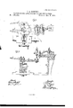
- Figure 1 is a perspective view of an enginelathe (omitting the head-stock) fitted with my attachment.
- Fig. 2 is a plan of the-attachment, showing also, in outline, the positions of the parts at two points in the work. Fig.
- d is an inside tool, clamped onto the swing-plate, as shown.
- the pivot to is un der one end of the plate, the other extending toward the tail-stock, where it has pivoted to it, at e, an upright yoke, 1, on each of whose side pillars is a friction-sleeve, f.
- J is a guideplate, fastened at one end by a set-screw, g, to the tail-stock, in the longitudinal axis thereof.
- the tail-center is removed from the tail-mandrel, and in its place is inserted a conical steady-pin at the back of a block, K, on whose head the guide-plate J rests, and to which it is adjust-ably secured by a set-screw, h, passing through a segment-slot in said plate, and tapped into said block.
- the sides of the guide-plate are parallel, and its width is such that it will enter between the rollers of the side pillars of the yoke, or rather that they will embrace it when moved with the carriage.
- the hole may be bored from either end clear through, or partly through, and finished straight, by clamping the tool-plate and running back the tail-mandrel, so as to detach the guideplate, and, it necessary, the work can then be faced up.
- the cut of the tool can be adjusted by the traverse-screw in the usual way.
Landscapes
- Drilling And Boring (AREA)
Description
ZSheets-Sheetl. P. L. ROGERS;
TAPER BORING ATTACHMENT TO ENGINE LATHES. I 1' 185,136; Patented Dec. 5, 1876.
THE GRAPHIC CU-PLY PETER L. ROGERS, OF BAY CITY, MICHIGAN.
IMPROVEMENT IN TAPER-BORING ATTACHMENTS TO ENGlNE-LATHES.
Specification forming part of Letters Patent No. 185,136, dated December 5, 1876; application filed June 6, 1876.
To all whom it may concern:
Be it known that 1, PETER L. ROGERS, of Bay City, in the county of Bay and State of- Michigan, have invented a new and useful Attachment to Engine-Lathes for Boring Tapers, of which the following is a specification;
The object I have in view is to provide a simple, but efiective and very cheap, attachment to an engine-lathe, for turning or boring holes in metal to any desired taper, consisting, merely, of a swinging tool-carrier pivoted to the traverse-stand of the carriage, with a guide-yoke pivoted to its tail end, and an adjustable guide secured to the tail-stock and tail-mandrel of the lathe, as more fully hereinafter set forth. 4
Figure 1 is a perspective view of an enginelathe (omitting the head-stock) fitted with my attachment. Fig. 2 is a plan of the-attachment, showing also, in outline, the positions of the parts at two points in the work. Fig.
-3 is a longitudinal vertical section.
the plate in position, but are not screwed tight enough to bind it, leaving it free to swing on the axis. d is an inside tool, clamped onto the swing-plate, as shown. The pivot to is un der one end of the plate, the other extending toward the tail-stock, where it has pivoted to it, at e, an upright yoke, 1, on each of whose side pillars is a friction-sleeve, f. J is a guideplate, fastened at one end by a set-screw, g, to the tail-stock, in the longitudinal axis thereof. The tail-center is removed from the tail-mandrel, and in its place is inserted a conical steady-pin at the back of a block, K, on whose head the guide-plate J rests, and to which it is adjust-ably secured by a set-screw, h, passing through a segment-slot in said plate, and tapped into said block. The sides of the guide-plate are parallel, and its width is such that it will enter between the rollers of the side pillars of the yoke, or rather that they will embrace it when moved with the carriage.
To bore a taper ot' a given angle, all that is required is to adjust the guide-plate to the same angle with relation to the axis and We of the lathe; then, as the yoke moves along the guide-plate, it will swing the plate in one direction and the tool in the opposite direction, causing it to bore the hole out to the angle or taper given by the guide.
The hole may be bored from either end clear through, or partly through, and finished straight, by clamping the tool-plate and running back the tail-mandrel, so as to detach the guideplate, and, it necessary, the work can then be faced up. The cut of the tool can be adjusted by the traverse-screw in the usual way.
What I claim as my invention is- In a taper-boring attachment to an-enginelathe, the combination of the tool-p1ate,adapted to swing on the traverse-standard, the yoke, pivoted to the tail end thereof, and the guide-plate, adapted to be adjustably secured to the tail-stock, substantially as described.
PETER L. ROGERS. Witnesses:
H. S. SPRAGUE, EDWARD BARTHEL.
Publications (1)
| Publication Number | Publication Date |
|---|---|
| US185136A true US185136A (en) | 1876-12-05 |
Family
ID=2254541
Family Applications (1)
| Application Number | Title | Priority Date | Filing Date |
|---|---|---|---|
| US185136D Expired - Lifetime US185136A (en) | Improvement in taper-boring attachments to engine-lathes |
Country Status (1)
| Country | Link |
|---|---|
| US (1) | US185136A (en) |
Cited By (1)
| Publication number | Priority date | Publication date | Assignee | Title |
|---|---|---|---|---|
| US20160236371A1 (en) * | 2015-02-18 | 2016-08-18 | Tillman Tazwell Bramlette, III | Hollowing System for a Wood Lathe |
-
0
- US US185136D patent/US185136A/en not_active Expired - Lifetime
Cited By (1)
| Publication number | Priority date | Publication date | Assignee | Title |
|---|---|---|---|---|
| US20160236371A1 (en) * | 2015-02-18 | 2016-08-18 | Tillman Tazwell Bramlette, III | Hollowing System for a Wood Lathe |
Similar Documents
| Publication | Publication Date | Title |
|---|---|---|
| US185136A (en) | Improvement in taper-boring attachments to engine-lathes | |
| US822754A (en) | Pulley-crowning attachment for lathes. | |
| US849414A (en) | emil tmueller | |
| US267354A (en) | lisle | |
| US1238478A (en) | Machine for reboring engine-cylinders. | |
| US195769A (en) | Improvement in tool-posts for lathes | |
| US652860A (en) | Detachable taper-cutting attachment for lathes. | |
| US135064A (en) | Improvement in metal-turning lathes | |
| US237487A (en) | Philetus b | |
| US787690A (en) | Lathe. | |
| US1259531A (en) | Tool post or holder for metal-working machines, such as lathes, planing-machines, shaping-machines, and the like. | |
| US809353A (en) | Lathe attachment. | |
| US595288A (en) | Lathe-slide | |
| US158007A (en) | Improvement in chucks | |
| US806996A (en) | Screw-cutting lathe. | |
| US327343A (en) | stevens | |
| US491521A (en) | Island | |
| US1088850A (en) | Lathe. | |
| US1438138A (en) | Combination tool | |
| US1363222A (en) | Angle-plate | |
| US221392A (en) | Improvement in lathe attachments for turning lathe-centers | |
| US1442661A (en) | Taper attachment for lathes | |
| US682405A (en) | Lathe. | |
| US982034A (en) | Lathe. | |
| US1222021A (en) | Lathe taper attachment. |