US1851342A - Grease gun - Google Patents
Grease gun Download PDFInfo
- Publication number
- US1851342A US1851342A US543282A US54328231A US1851342A US 1851342 A US1851342 A US 1851342A US 543282 A US543282 A US 543282A US 54328231 A US54328231 A US 54328231A US 1851342 A US1851342 A US 1851342A
- Authority
- US
- United States
- Prior art keywords
- conduit
- spout
- fitting
- coact
- discharge
- Prior art date
- Legal status (The legal status is an assumption and is not a legal conclusion. Google has not performed a legal analysis and makes no representation as to the accuracy of the status listed.)
- Expired - Lifetime
Links
- 239000004519 grease Substances 0.000 title description 12
- 239000000314 lubricant Substances 0.000 description 18
- 230000008878 coupling Effects 0.000 description 8
- 238000010168 coupling process Methods 0.000 description 8
- 238000005859 coupling reaction Methods 0.000 description 8
- 230000004048 modification Effects 0.000 description 2
- 238000012986 modification Methods 0.000 description 2
- BWWVAEOLVKTZFQ-NTZNESFSSA-N Amdinocillin Chemical compound N([C@H]1[C@H]2SC([C@@H](N2C1=O)C(O)=O)(C)C)=CN1CCCCCC1 BWWVAEOLVKTZFQ-NTZNESFSSA-N 0.000 description 1
- 238000009825 accumulation Methods 0.000 description 1
- 230000032683 aging Effects 0.000 description 1
- 230000000295 complement effect Effects 0.000 description 1
- 230000001050 lubricating effect Effects 0.000 description 1
- 238000000034 method Methods 0.000 description 1
Images
Classifications
-
- F—MECHANICAL ENGINEERING; LIGHTING; HEATING; WEAPONS; BLASTING
- F16—ENGINEERING ELEMENTS AND UNITS; GENERAL MEASURES FOR PRODUCING AND MAINTAINING EFFECTIVE FUNCTIONING OF MACHINES OR INSTALLATIONS; THERMAL INSULATION IN GENERAL
- F16N—LUBRICATING
- F16N3/00—Devices for supplying lubricant by manual action
- F16N3/10—Devices for supplying lubricant by manual action delivering grease
- F16N3/12—Grease guns
Definitions
- This invention relates to dispensing appa- ⁇ ratus and particularly 'to grease guns that are adapted for use in dispensing lubricant through fittings, which are attached to the 5 bearings and other parts to be lubricated.
- fittings which are attached to the 5 bearings and other parts to be lubricated.
- the most prominent kinds of fittings are known in the trade as the Zerk and Alemite fittings.v A
- the Zerk type necessitates the use of manual pressure '10 to hold the coupler'in contact with themitting during the dispensing operation.
- the tting is rigidly attached to the discharge spout, and where a iiexible hose is used, the end that carries the coupling mustfbe held rigidly 2 pressure to holdthe coupling, in place,A As v it .is Anecessary however, for garages and service stations to provide equipment to service either type of tting, the practice has been to make the Zerk coupler detachable and replaceable by the Alemite coupler.
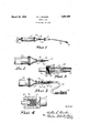
- Fig. l is a side elevation of a grease gun embodying my invention and showing the Alemite adapter removed from the gun;
- Fig. 2 is an elevation partly, in section on an enlarged the adapter, and
- Fig. 5 is a longitudinal sec.
- hose 15 which carries the Alemite coupler 16.
- The' opposite or intake end of the hose is then provided with an enlarged tubular 'caslng 18, that 4extends over the Zerk coupler and part of the4 discharge spout.
- Such casing is provided with a seat'l9 that is adapted to engage the end of the discharge spout, and to provide a grease tight joint therewith.
- the-discharge conduit 12 As having a threaded portion 20 thereon, which is adapted to be engaged by a corresponding internal- ,ly ⁇ threaded portion 22 on the sleeve.
- a threaded portion 20 is protected by a nut 23, which has a flange 24 that is spun on the end of the nut adjacent the barrel and which retains the nut on'tlie spout when it is'disengaged from' the thread.
- the nut is backed olf the thread andthe Alemite' adapter is placed over the conduit and screwed tightly thereon. Thereupon grease is dispensed through the hose without leakage, and without necessitating removal of the Zerk coupler.
- the end of the hose is formed to coact with a Zerk fitting.Vv
- the hose carrying the Alemite coupler is f1tted overvthe Zerk coupler, so that lubrticant maybe dispensed without necessitating thev removal of the Zerk coupler.
- Fig. 5 I have shown a modification of my invention, wherein a union joint is made between the casing 30 and the discharge spout 3l. Provision is then made for enabling the casing to be slid longitudinally of the spout but to be prevented from rotating-with reference thereto, preferably by means of a hexagonal portion 38, which extends lengthwise of the spout and a coacting complementary shaped portion 32 on the inner part of the casing.
- the end of the casing is then provided with a shoulder 33, which is engaged by a nut 34, and which acts when threaded onto the spout 31, to make a lubricant tight joint between the casing and the spout.
- An advantage of the modified-form is that there is no danger of the joint'between the casing and spout being loosened 'if the gun should be turned inadvertently by the operator while the pressure is on.-
- a further advantage ofthe modified form is the fact that an opening 36 in the wall of the casing enables the pressure to be reduced in the discharge conduit, to permit removal of thecoupler merely by loosening the nut 34C. The release of pressure can likewise be accomplished by breaking the joint between the casing 18 and the threaded portion 20, but the use of the lateral opening 36 prevents the accumulation of lubricant adjacentthe threaded portion, where it is apt to vsmear the hands and clothing each time the replacement is made.
- a discharge spout formed to coact with one type of fitting, said spout having a threaded portion spaced from the end thereof, and having a noncircular periphery disposed between the threaded portion and the end of the spout, a ⁇ casing slidably mounted along the nonthreaded portion and being adapted to provide a lubricant tight seal with the spout, said casing having a non-circular portlon on the interior thereof for coactin g with the noncircular part of the spout to prevent rotation of the casing with reference to the spout, a nut on the casing and adapted to coact with the threaded portion to lock the casing to the discharge condult formed at one end therespout, and means carried by the casing for coacting with a different type of fitting.
- a lubricant dispensing device for use in connection with a grease gun having a discharge conduit formed at the end thereof to coact with one type ofiitting, and having a threaded portion remote from the end of the conduit; comprising a iiexible conduit having means thereon adapted to receive the end of the discharge conduit and to engage the threaded portion thereon, and to provide a lubricant tight joint therewith, said flexible conduit being provided with a coupling tocoact. with a different type of fitting.
- a lubricant dispensing device for use in connection with a ease rgun having a discharge spout rigid-t erewith, said spout having the end thereof formed to coact with one type of fitting; comprising a flexible conduit and means extending along the exterior and across the discharge end of the spout and making a Huid tight joint between the conduit and spout, said conduit having a coupling at the free end thereof adapted to coact with a different type of fitting.
- a lubricant dispensing device for use in connection with a grease gun having a discharge member, adapted to coact with one type of fitting; comprising an auxiliary conduit, saidl conduit being adapted to coact Witha different type of fitting, means for enabling the conduit to be extended over the end of the member, means for preventing rotation of the conduit with reference to the member, and other means for locking the conduit to the member, and to provide a lubricant tight joint therewith.
- a lubricant dispensing device for use in connection with-a grease gun having a discharge spout and having the end thereof formed to coact with one type of fitting; comprising a conduit adapted to be splined on the spout and to make a lubricant tight joint therewith, means for locking the conduit to the spout, said conduit being adapted to coact with a different type of fitting and having a pressure release opening extending therethrough between the point of locking connection and the point :of lubricant tight seal therewith.
- a lubricant dispensing device for use in connection with a grease gun having a discharge spout formed to coact with one type of fitting, comprising an auxiliary iiexible conduit adapted to coact with a different type of fitting, said conduit being formed to receive the spout, and to provide a lubricant tight joint therewith, and means for interlocking the spout and conduit, said means being adapted when released, to relieve the pressure at said joint whereby the coupling may be removed from the fitting while under pressure.
- A' lubricant dispensing device for use in connection With a grease gun having a rigid of to coact with one type 'of fitting, comprising a flexible conduit having a coupling at the free end thereof formed to coact with a different type of fitting, and means for making a lubricant tight joint between the conduits, said means including a threaded member slidably mounted on one of the conduits and a coacting threaded portion on the other conduit.
- a lubricantdispensing device for use in connection with a grease gun having a rigid discharge conduit formed at one end thereof to coact with one type of fitting, comprising a exble conduit having a coupling at the free endthereof formed to coact with a dierent type of ttin and means for making a lubri-v cant tight jomt between the conduits, said means mcluding a, valve seat carried'by the 5 ⁇ flexible conduit and engaging the end of the discharge conduit, and intere aging members on the conduits for locking t em together i lubricant conducting relatlonship.
Landscapes
- Engineering & Computer Science (AREA)
- General Engineering & Computer Science (AREA)
- Mechanical Engineering (AREA)
- Coating Apparatus (AREA)
Description
March 29, 1932. R, L. BACHER 1,851,342
GREASE GUN Filed June v1o 1,931
Patented Mar. 29,' 1932 l UNi'rEn STATES PATENT orFlcE i BOLLIN' L.. TEACHER, OF LAKEWOOD, OHIO, -ASSIGNOR TO THE UNITED STATES AIRCOM- PRESSOB COMPANY, F CLEVELAND, OHIO, A. CORPORATION OIF OHIO Gnnasn een Application mea-June 1o, 1931. serial No. 543,282.
This invention relates to dispensing appa-` ratus and particularly 'to grease guns that are adapted for use in dispensing lubricant through fittings, which are attached to the 5 bearings and other parts to be lubricated. t the present time, the most prominent kinds of fittings are known in the trade as the Zerk and Alemite fittings.v A The Zerk type necessitates the use of manual pressure '10 to hold the coupler'in contact with themitting during the dispensing operation. Accordingly where a hand gun vis used, the tting is rigidly attached to the discharge spout, and where a iiexible hose is used, the end that carries the coupling mustfbe held rigidly 2 pressure to holdthe coupling, in place,A As v it .is Anecessary however, for garages and service stations to provide equipment to service either type of tting, the practice has been to make the Zerk coupler detachable and replaceable by the Alemite coupler.
This procedure however, has been found to be objectionable for the Zerk coupler is relatively small, and therefore is apt to be lost or mislaid .when it isv detached from the hose. v
in the same manner as that' heretoforeused for the same purpose. v
Referring now to the drawings, Fig. l is a side elevation of a grease gun embodying my invention and showing the Alemite adapter removed from the gun; Fig. 2 is an elevation partly, in section on an enlarged the adapter, and Fig. 5 is a longitudinal sec.
tion through a device embodying a modification of my invention.
I have shown my'invention in connection Witha hand-operated grease-gun wherein l0 indicates the barrel of the gun, 11 the operating handle, and 12 the discharge conduit that leads tromvthe barrel. Such last named conduit is shaped adjacent y the discharge end thereof, as at 13, to coact with a Zerk7 type fitting, and inasmuch as'the entire discharge conduit is rigid with the barrel, it is apparent 'that the manual pressure which must be exerted'to maintain the coupling in contact withthe fitting can readily be applied.
To adapt the gun for use with the Alemite fitting, I provide a short length of hose 15, which carries the Alemite coupler 16. The' opposite or intake end of the hose is then provided with an enlarged tubular 'caslng 18, that 4extends over the Zerk coupler and part of the4 discharge spout. Such casing is provided with a seat'l9 that is adapted to engage the end of the discharge spout, and to provide a grease tight joint therewith.-
To connect the sleeve to the gun, I have shown the-discharge conduit 12 as having a threaded portion 20 thereon, which is adapted to be engaged by a corresponding internal- ,ly `threaded portion 22 on the sleeve. Normally, such threaded portion is protected by a nut 23, which has a flange 24 that is spun on the end of the nut adjacent the barrel and which retains the nut on'tlie spout when it is'disengaged from' the thread. VWhenever" it is desired therefore, to use the gun for lubricating 'through Alemite fittings, the nut is backed olf the thread andthe Alemite' adapter is placed over the conduit and screwed tightly thereon. Thereupon grease is dispensed through the hose without leakage, and without necessitating removal of the Zerk coupler. j
Where a hose is used in place of the hand operatedV gun, the end of the hose is formed to coact with a Zerk fitting.Vv In eithen'- case, the hose carrying the Alemite coupler is f1tted overvthe Zerk coupler, so that lubrticant maybe dispensed without necessitating thev removal of the Zerk coupler.
In Fig. 5, I have shown a modification of my invention, wherein a union joint is made between the casing 30 and the discharge spout 3l. Provision is then made for enabling the casing to be slid longitudinally of the spout but to be prevented from rotating-with reference thereto, preferably by means of a hexagonal portion 38, which extends lengthwise of the spout and a coacting complementary shaped portion 32 on the inner part of the casing.
The end of the casing is then provided with a shoulder 33, which is engaged by a nut 34, and which acts when threaded onto the spout 31, to make a lubricant tight joint between the casing and the spout.
An advantage of the modified-form is that there is no danger of the joint'between the casing and spout being loosened 'if the gun should be turned inadvertently by the operator while the pressure is on.- A further advantage ofthe modified form is the fact that an opening 36 in the wall of the casing enables the pressure to be reduced in the discharge conduit, to permit removal of thecoupler merely by loosening the nut 34C. The release of pressure can likewise be accomplished by breaking the joint between the casing 18 and the threaded portion 20, but the use of the lateral opening 36 prevents the accumulation of lubricant adjacentthe threaded portion, where it is apt to vsmear the hands and clothing each time the replacement is made. l
l. In combination in a lubricant dispenser, a discharge spout formed to coact with one type of fitting, said spout having a threaded portion spaced from the end thereof, and having a noncircular periphery disposed between the threaded portion and the end of the spout, a` casing slidably mounted along the nonthreaded portion and being adapted to provide a lubricant tight seal with the spout, said casing having a non-circular portlon on the interior thereof for coactin g with the noncircular part of the spout to prevent rotation of the casing with reference to the spout, a nut on the casing and adapted to coact with the threaded portion to lock the casing to the discharge condult formed at one end therespout, and means carried by the casing for coacting with a different type of fitting.
2. A lubricant dispensing device for use in connection with a grease gun having a discharge conduit formed at the end thereof to coact with one type ofiitting, and having a threaded portion remote from the end of the conduit; comprising a iiexible conduit having means thereon adapted to receive the end of the discharge conduit and to engage the threaded portion thereon, and to provide a lubricant tight joint therewith, said flexible conduit being provided with a coupling tocoact. with a different type of fitting.
3. A lubricant dispensing device for use in connection with a ease rgun having a discharge spout rigid-t erewith, said spout having the end thereof formed to coact with one type of fitting; comprising a flexible conduit and means extending along the exterior and across the discharge end of the spout and making a Huid tight joint between the conduit and spout, said conduit having a coupling at the free end thereof adapted to coact with a different type of fitting.
4. A lubricant dispensing device for use in connection with a grease gun having a discharge member, adapted to coact with one type of fitting; comprising an auxiliary conduit, saidl conduit being adapted to coact Witha different type of fitting, means for enabling the conduit to be extended over the end of the member, means for preventing rotation of the conduit with reference to the member, and other means for locking the conduit to the member, and to provide a lubricant tight joint therewith.
5. A lubricant dispensing device for use in connection with-a grease gun having a discharge spout and having the end thereof formed to coact with one type of fitting; comprising a conduit adapted to be splined on the spout and to make a lubricant tight joint therewith, means for locking the conduit to the spout, said conduit being adapted to coact with a different type of fitting and having a pressure release opening extending therethrough between the point of locking connection and the point :of lubricant tight seal therewith.
6. A lubricant dispensing device for use in connection with a grease gun having a discharge spout formed to coact with one type of fitting, comprising an auxiliary iiexible conduit adapted to coact with a different type of fitting, said conduit being formed to receive the spout, and to provide a lubricant tight joint therewith, and means for interlocking the spout and conduit, said means being adapted when released, to relieve the pressure at said joint whereby the coupling may be removed from the fitting while under pressure.
7. A' lubricant dispensing device for use in connection With a grease gun having a rigid of to coact with one type 'of fitting, comprising a flexible conduit having a coupling at the free end thereof formed to coact with a different type of fitting, and means for making a lubricant tight joint between the conduits, said means including a threaded member slidably mounted on one of the conduits and a coacting threaded portion on the other conduit.
y 8. A lubricantdispensing device for use in connection with a grease gun having a rigid discharge conduit formed at one end thereof to coact with one type of fitting, comprising a exble conduit having a coupling at the free endthereof formed to coact with a dierent type of ttin and means for making a lubri-v cant tight jomt between the conduits, said means mcluding a, valve seat carried'by the 5 `flexible conduit and engaging the end of the discharge conduit, and intere aging members on the conduits for locking t em together i lubricant conducting relatlonship. Y
' In testimony whereof, I hereunto ax my l0 signature.
ROLLIN L. BACHER.
Priority Applications (1)
| Application Number | Priority Date | Filing Date | Title |
|---|---|---|---|
| US543282A US1851342A (en) | 1931-06-10 | 1931-06-10 | Grease gun |
Applications Claiming Priority (1)
| Application Number | Priority Date | Filing Date | Title |
|---|---|---|---|
| US543282A US1851342A (en) | 1931-06-10 | 1931-06-10 | Grease gun |
Publications (1)
| Publication Number | Publication Date |
|---|---|
| US1851342A true US1851342A (en) | 1932-03-29 |
Family
ID=24167335
Family Applications (1)
| Application Number | Title | Priority Date | Filing Date |
|---|---|---|---|
| US543282A Expired - Lifetime US1851342A (en) | 1931-06-10 | 1931-06-10 | Grease gun |
Country Status (1)
| Country | Link |
|---|---|
| US (1) | US1851342A (en) |
Cited By (4)
| Publication number | Priority date | Publication date | Assignee | Title |
|---|---|---|---|---|
| US2499659A (en) * | 1948-01-05 | 1950-03-07 | Arlie F Lockwood | Swivel coupler for grease guns |
| US2823699A (en) * | 1953-11-20 | 1958-02-18 | Willis Oil Tool Co | Valved coupling embodying fluid pressure actuated locking means |
| US3016161A (en) * | 1958-08-08 | 1962-01-09 | Lakewood Mfg Co | Flexible filler tube assembly |
| US3529020A (en) * | 1965-08-16 | 1970-09-15 | Mobil Oil Corp | Oxidation processes employing aluminosilicate catalysts and an initiator |
-
1931
- 1931-06-10 US US543282A patent/US1851342A/en not_active Expired - Lifetime
Cited By (4)
| Publication number | Priority date | Publication date | Assignee | Title |
|---|---|---|---|---|
| US2499659A (en) * | 1948-01-05 | 1950-03-07 | Arlie F Lockwood | Swivel coupler for grease guns |
| US2823699A (en) * | 1953-11-20 | 1958-02-18 | Willis Oil Tool Co | Valved coupling embodying fluid pressure actuated locking means |
| US3016161A (en) * | 1958-08-08 | 1962-01-09 | Lakewood Mfg Co | Flexible filler tube assembly |
| US3529020A (en) * | 1965-08-16 | 1970-09-15 | Mobil Oil Corp | Oxidation processes employing aluminosilicate catalysts and an initiator |
Similar Documents
| Publication | Publication Date | Title |
|---|---|---|
| US2333243A (en) | Detachable coupling | |
| US3064998A (en) | Lockable swivel pipe coupling | |
| US1983840A (en) | Compression coupling | |
| US2443394A (en) | Coupling for hoses and pipes | |
| US2423069A (en) | Swivel attachment for couplers | |
| US4195812A (en) | Coupler for grease guns | |
| US2033142A (en) | Coupling device | |
| US1851342A (en) | Grease gun | |
| US1995377A (en) | Lubricating device | |
| US2006833A (en) | Hose nozzle | |
| US2176295A (en) | Lubricating device | |
| US1711870A (en) | Lubricating means | |
| US1883279A (en) | Lubricating coupler | |
| US2298117A (en) | Quick coupler for tubing | |
| US2061086A (en) | Lubricating apparatus | |
| US1750790A (en) | Coupling | |
| US2016809A (en) | Lubricating apparatus | |
| US1859251A (en) | Coupling | |
| US2404052A (en) | Lubrication coupler | |
| US2059704A (en) | Lubricant nozzle extension | |
| US1850860A (en) | Coupler | |
| US1874541A (en) | Lubricating device | |
| US2147835A (en) | Lubricating apparatus | |
| US1970845A (en) | Lubricating device | |
| US2040177A (en) | Hydraulic lubricating connection |