US1851337A - Mowing machine - Google Patents
Mowing machine Download PDFInfo
- Publication number
- US1851337A US1851337A US515045A US51504531A US1851337A US 1851337 A US1851337 A US 1851337A US 515045 A US515045 A US 515045A US 51504531 A US51504531 A US 51504531A US 1851337 A US1851337 A US 1851337A
- Authority
- US
- United States
- Prior art keywords
- disposed
- cutter
- car
- cutter head
- bar
- Prior art date
- Legal status (The legal status is an assumption and is not a legal conclusion. Google has not performed a legal analysis and makes no representation as to the accuracy of the status listed.)
- Expired - Lifetime
Links
- 230000000712 assembly Effects 0.000 description 2
- 238000000429 assembly Methods 0.000 description 2
- 230000035939 shock Effects 0.000 description 2
- 210000000707 wrist Anatomy 0.000 description 2
- 240000001439 Opuntia Species 0.000 description 1
- 241001225883 Prosopis kuntzei Species 0.000 description 1
- 229920000136 polysorbate Polymers 0.000 description 1
Images

Classifications
-
- A—HUMAN NECESSITIES
- A01—AGRICULTURE; FORESTRY; ANIMAL HUSBANDRY; HUNTING; TRAPPING; FISHING
- A01D—HARVESTING; MOWING
- A01D34/00—Mowers; Mowing apparatus of harvesters
- A01D34/01—Mowers; Mowing apparatus of harvesters characterised by features relating to the type of cutting apparatus
- A01D34/02—Mowers; Mowing apparatus of harvesters characterised by features relating to the type of cutting apparatus having reciprocating cutters
- A01D34/03—Mowers; Mowing apparatus of harvesters characterised by features relating to the type of cutting apparatus having reciprocating cutters mounted on a vehicle, e.g. a tractor, or drawn by an animal or a vehicle
Definitions
- a second pair of, cutting heads are supported uponthe caredapted for cutting outside of the rails to the length cf the ties with one cutting head and having hingedly' secured cutting a limited distance beyond the end of portionof cutting head to the desired angle to meetthe requirements and grades. 7 g
- Independentmeens are provl ing. each one independently and all of the cut ⁇ . ter heads at one, time; means is turther pres 'vid-ed for driving-theifiatcar 1n fiithel dlr rectiQn.
- 1 hThe ohject ofmy invention 1s to-p ioiflde a. self-propelling mowing ⁇ machine for, the
- r ay tracks otreilway' ygte V the cost'of the cuttingfof the -vegetationwa'lcng and lowering the cutting headidispcsed be-' thereto, asecond cutting headadaptedfcn dedfcridrfifi g ofthe'drive mechanism.
- Fig.2 1s esectionel top,cplan; view of the assembled devlce the same beingtakencn line cated.
- Figs. is ln inverted; plan .view ofthe 7G esse'mbied (18V1CQ..- I i I f Fig; ,6 1s a fragmentary, sectional; side View j Fig. 7 is a fragmentary, sectional, end View .of-the Iiiech anism illustrated inFig. '6, the .75
- gEig. 1 1' is e; sectienel;"sideyyiew lot the I hlngedj olntconnecting the cutter. bar dis- [p osed eboutihe utside of the-tieto the cut- 19c ter bar disposed'g abovethetiei the same, being taken on line 11 110151 ig.- 10,"lc0king in" the di'rectiomindicated.”
- i Fig.1 12 is a. .fragmentery side iew ,of.
- Fig.13 is efragmentery, front-view cit-he support for supporting,adjusting and rais ,i'ng thehinged'cutter head assemblyfdispesed, V
- i I g nn Fig. 14 is a fragmentary, front View of the mechanism illustrated in Fig. 13, and illustrating the hinged cutter head raised and in inoperative position.
- jack shaft. 8 is disposed transversely of thecar and is adapted for being driven by the prime mover,through any suitable drive elemerits as through the use of a belt or chain 9.
- the jack shaft 8 is mounted upon a-bracket 10 that de ends from the underside of the platform an is secured thereto by any suitable fastening means as through the use of bolts 11 and 12. v
- a driving pulley 13 is'mounted upon the front axle? and a driving element as a chain or belt 14 is trained about a suitable pulley 15 that is mounted upon the jack shaft 8.
- Apulley or sprocket 16 is mounted upon the shaft 6 and a tight pulley 17 and a lose pulley 18 are mounted adjacent each other upon the shaft 8 and a suitable driving element as a belt 19 is trained'about the respective tight and loose pulleys 1.7 and 18 and the pulley 16, mounted'upon'the shaft 6.
- This drive assembly permits the forward and back movements of the car u on the track through the use of suitable belt s rifters and belt tighteners,
- I Asecond jack shaft 20 is mounted within the frame of the car and driving clutches are mounted upon the shaft 20.
- a cutter bar'21 is disposed central of the ⁇ car and is ofsufiicient length to be placed between the rails 2 and 3.
- a sickle bar 22 is reciprocably disposed upon the cutter bar with guards being disposed u on the cutter bar through whichvthe sickle ar is reciprocate'd.
- a crank disk 24 is mounted upon the shaft 23 and a crankpin 25 is secured to the crank disk 24.
- a pitman rod 26 connects the crank pin 25 with a wrist pin 27 that is secured to the sickle 1 bar, andthe driving disk and as the pitman rod is reciprocated, the sickle bar is alsoreeiprocated.
- a slip joint is disposed between the primary rod and the sleeve 28 and compensates for the difference in the spacing between the wrist pin 27 and the pitmanrod 26.
- the cutter head assembly- is suspended upon a yoke 29 that is secured upon its oppositely dis osed ends to guide bars 30 and 31.
- the gui e bars 30 and 31 pass upward through guideways 32 and 33 that are secured directly to the primary frame of the car.
- a link is connected upon its one end to the 119729 and upon its oppositely disposed end
- the innermost sickle bar of each pair of heads is adapted to cut'to: the outerlength of the tie and between the'outer surface of the rail and the tie and the outer one ofthe sickle bars of each pair, is adapted to'cut at a different elevation and beyond the length of the tie to the desired length 'to be cut for the particular use to whichthesame is'to be adapted.
- the outer sickle bar and cutter head assembly is hingedly secured relative to the inner sickle bar and cutter head assembly.
- Eachof the sickle bars disposed at the oppositely disposed sides f'the mowing machine are adapted for being driven by acommon driving-element.
- Coacting gears 0 and '41 are mounted respectively the disk.,.
- A. pitman rod 46 is secured to the crank pin 4 5'upon its one end and'to a bell crank 47 upon its oppositely disposed end.
- .T he bellcrank 47 is secured to and adapted for reciprocating the sickle bars 48 and 49 respectively, each being an. independent sickle banand adapted for being operated at difi'eremt elevations, to cut the vegetation at different elevations adjacent the track and tie, and
- r 1 1- r J Shoes 52 and 53 are disposed immediately below the cutter head assembly and each of thesshoes areadapted for engaging the surface of the earth adj acent the outer end of the
- the cutter 7 side or the car is comprisedof two independentsickle -bars and cutter bars associated therewith, the same being hingedly secured together.
- Fig. 10 isadaptedfor being hingedly secured about: a supporting pin andthe outer cutter barassembly 56 is hingedly secured, relative to the cutt'erbar 54,
- outer cutter bar assembly may be fiexiblysupported by a chain or.
- cable 58 and a tension" rod 68 one end of which isfa'stened to a lug 59 outwardly extending from the cutter bar 54, the oppositely disposed end being secured to a lug 60 secured to theouter cutter bar 1 with a reacting element 61, as 346011 spring thread, 69 is disposed upon one end of the tensioning rod 68 and looking nuts 7 0 and 71 disposed therebetween.
- a relatively long are disposed at the oppositely disposedsides of the lug 59 in order to properly tension the rod 68 and to maintain the-cutter bar in precise elevation.
- A-lever 62 is adapted for raising and lowering the pair ofsickle barassemblies.
- An arm 7 63 is disposed at right angles to the lever 62.
- link 64 connects the arm 63 with the lug 65 that outwardly extends from the inner end of the cutter'bar assemblyi54t A quadrant 66 associated with the hand lever 62 for maintaining the sickle bar assembly in desired" 5 placed position and elevation.
- a device of the class described, compris'-:
- Struts 7 5 ⁇ and 76' also connect the cutter head assembly disposed upon theoutside ofthe car a platform ,to the frame of the car for absorbing any shocks that may be imparted to the. side cutter head assembly
Landscapes
- Life Sciences & Earth Sciences (AREA)
- Zoology (AREA)
- Environmental Sciences (AREA)
- Harvester Elements (AREA)
Description
March 29, 1932.
P. E. WAL KER MOWING MACHINE Filed Feb. ll, 1951 4 Sheets-Sheet 1 ATTORN I Ewes IN E, L/a/A'er Q INVENTOR I March 29, 1932.
P. E. WALKER MOWING MACHINE Filed Feb. 11. 1931 I 4 Sheets-Sheet 2 Brew/w if. A/d/A'el INVENTOR ATTOR March 29, 1932. p, WALKER 1,851,337
MOWING MACHINE Filed Feb. 11. I951 4 Sheets-Sheet 3 ATTORNE March 29, 1932. P" E. WALKER MOWING MACHINE 4 Sheets-Sheet 4 Filed Feb. 11. 1951 see s Mame, 1932; i '7 I PEB VILII WALKER; ben oii mqcx, CREGON f Y 7 Ap plicatiojn filedFcbruery.11 ,193f.1:,Seri2i1 330.;5150451 lviy; inizenticn is intended ior'use inlthe cutting of vegetation between-the tra'cks and outside 0i thelraiis ofrailways' zind consists ed for cutting the vegetation between ther'ails and adjacent the 'ties with meanstor raising 'tween'the'rail's. v I 1 J A second pair of, cutting heads are supported uponthe caredapted for cutting outside of the rails to the length cf the ties with one cutting head and having hingedly' secured cutting a limited distance beyond the end of portionof cutting head to the desired angle to meetthe requirements and grades. 7 g
Independentmeens are provl ing. each one independently and all of the cut}. ter heads at one, time; means is turther pres 'vid-ed for driving-theifiatcar 1n fiithel dlr rectiQn. 1 hThe ohject ofmy invention: 1s to-p ioiflde a. self-propelling mowing {machine for, the
thetracks.cf railways, f A further ob ect of 1y inyentlo n cons sts in providing a self-propelling mow nginm chine having gselective speeds, at hichfithe same may be drivenrand providing a vmowing machine thatwiilcut'the vegetatien adjacent 1 thetmcksch either side zind lbettiiee "the railsjin a single passage over the r'ailsq;
' sists in providing a mowing machineiorjrailwayuse that may beused inj'the Ctittlllg fa substantial mileage per b0111 tc'therehy limlt:
r ay tracks otreilway' ygte V the cost'of the cuttingfof the -vegetationwa'lcng and lowering the cutting headidispcsed be-' thereto, asecond cutting headadaptedfcn dedfcridrfifi g ofthe'drive mechanism. a
. inginJ- the direction indicated.
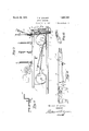
cutting ofl egetation ad acent between" V sists in'providing emowiiig mechineithat is i i 7 With .these 'a'nd incidentaljbbjectsin- View H the in entioniccnsists in certain nqvje fe? itbvoutithebuti egef theraillj' g of c rcnstru ction and i combinzitien parts, thejessentiallelementsof which are set t'orthin the appen ded claims, and a preferred form of embodiment of, which; is hereinafter shown withreference t0 the dr awingslwhich acccmpany and forni a part cf thisspecificixtidn' i In V Fig-.1 is a front View essenihleddei T vice. I
'EL. Fig.2 1s esectionel top,cplan; view of the assembled devlce the same beingtakencn line cated.
2-2 0f Fig.1, lockinginthe direction indi Fig. 3'is a side View of theassenibledde 5 v ce I r T h e F 1g. 4: 1s.a sect10nal, side.y iew of the asseml led device, the same being takenon line H I of Fig.1 1, lcoh ng n the direction indicated.
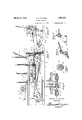
Figs. is ln inverted; plan .view ofthe 7G esse'mbied (18V1CQ..- I i I f Fig; ,6 1s a fragmentary, sectional; side View j Fig. 7 is a fragmentary, sectional, end View .of-the Iiiech anism illustrated inFig. '6, the .75
samebeingaken on line 7 ,ZofFig. 6;.lock
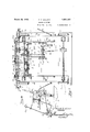
i w) [.1 "8;;is a perspective, frc t viewlcif hingedjsickle head that disposed upon. the gcuttm'g:head 'outside.of 'the rail "and -5 Q 1 a pt d' c ng OV llh fiie and out- Ward; on the right ofway-lfrcmthe-"end cf h tie Q I jig. 9 is asectionahsideview cf the mechanism illustrste'din Fig. 8. f 1 i .Fig. 10 is, a tepi plan; view; 9f the cutting;
headdispcsedjahcutthe outsidecf the rail.
gEig. 1 1' is e; sectienel;"sideyyiew lot the I hlngedj olntconnecting the cutter. bar dis- [p osed eboutihe utside of the-tieto the cut- 19c ter bar disposed'g abovethetiei the same, being taken on line 11 110151 ig.- 10,"lc0king in" the di'rectiomindicated."
i Fig.1 12 is a. .fragmentery side iew ,of. the
supperting'rod for supporting thehinged cutter head assembly.
Fig.13 is efragmentery, front-view cit-he support for supporting,adjusting and rais ,i'ng thehinged'cutter head assemblyfdispesed, V
i I g nn Fig. 14: is a fragmentary, front View of the mechanism illustrated in Fig. 13, and illustrating the hinged cutter head raised and in inoperative position.
Like references characters refer to like platform of the flat car. The wheels of the fiat car are mounted upon axles 6 and 7. A
jack shaft. 8 is disposed transversely of thecar and is adapted for being driven by the prime mover,through any suitable drive elemerits as through the use of a belt or chain 9.
While I have shown the drive as being driven by a'belt or chain I do notwish to be limited to this form of'd-rive, as the same may be driven with equal facility through the use of coacting gears and shafts, or by any other suitable driving mechanism.
The jack shaft 8 is mounted upon a-bracket 10 that de ends from the underside of the platform an is secured thereto by any suitable fastening means as through the use of bolts 11 and 12. v
A driving pulley 13 is'mounted upon the front axle? anda driving element as a chain or belt 14 is trained about a suitable pulley 15 that is mounted upon the jack shaft 8. Apulley or sprocket 16 is mounted upon the shaft 6 and a tight pulley 17 and a lose pulley 18 are mounted adjacent each other upon the shaft 8 and a suitable driving element as a belt 19 is trained'about the respective tight and loose pulleys 1.7 and 18 and the pulley 16, mounted'upon'the shaft 6. This drive assembly permits the forward and back movements of the car u on the track through the use of suitable belt s rifters and belt tighteners, I Asecond jack shaft 20is mounted within the frame of the car and driving clutches are mounted upon the shaft 20. The shaft 20'beingjournaled'within suitable journal boxes secured to the car platform and spaced'apart to maintain the shaft in alignment and in position,
A cutter bar'21 is disposed central of the {car and is ofsufiicient length to be placed between the rails 2 and 3. A sickle bar 22 is reciprocably disposed upon the cutter bar with guards being disposed u on the cutter bar through whichvthe sickle ar is reciprocate'd.
A crank disk 24 is mounted upon the shaft 23 and a crankpin 25 is secured to the crank disk 24. A pitman rod 26 connects the crank pin 25 with a wrist pin 27 that is secured to the sickle 1 bar, andthe driving disk and as the pitman rod is reciprocated, the sickle bar is alsoreeiprocated. A slip joint is disposed between the primary rod and the sleeve 28 and compensates for the difference in the spacing between the wrist pin 27 and the pitmanrod 26. The cutter head assembly-is suspended upon a yoke 29 that is secured upon its oppositely dis osed ends to guide bars 30 and 31. The gui e bars 30 and 31 pass upward through guideways 32 and 33 that are secured directly to the primary frame of the car.
A link is connected upon its one end to the 119729 and upon its oppositely disposed end,
to a pin '35. The pin 35 is secured to a lever 36,.the'purpose of which is to raise and lower the cutter head to the desired cutting elevatien. ,A quadrant, associated with the lever 36 for supporting the cutter head at the desired elevation. JCoacting gears 37 and 38 are mounted upon the shafts 23 and 24, respeetively, and a clutch 39 is mounted upon the shaft 20, the. purpose of which is to render the coacting gearsoperative and inoperative at the willof the'operator of the mowing machine; Q I
Sickle barsa-re disposed at the oppositely disposed sides of the car. The innermost sickle bar of each pair of heads is adapted to cut'to: the outerlength of the tie and between the'outer surface of the rail and the tie and the outer one ofthe sickle bars of each pair, is adapted to'cut at a different elevation and beyond the length of the tie to the desired length 'to be cut for the particular use to whichthesame is'to be adapted. Means'being provided for raising the cutter head as sembly as a whole, or-for raising the outer one independently of the-inner one, or for inclining the cuttin'g angle'of the outer siekle bar independent of the inner one. The outer sickle bar and cutter head assembly is hingedly secured relative to the inner sickle bar and cutter head assembly. Eachof the sickle bars disposed at the oppositely disposed sides f'the mowing machine are adapted for being driven by acommon driving-element. Coacting gears 0 and '41 are mounted respectively the disk.,. A. pitman rod 46 is secured to the crank pin 4 5'upon its one end and'to a bell crank 47 upon its oppositely disposed end.
.T he bellcrank 47 is secured to and adapted for reciprocating the sickle bars 48 and 49 respectively, each being an. independent sickle banand adapted for being operated at difi'eremt elevations, to cut the vegetation at different elevations adjacent the track and tie, and
particularly adjacent'that portion of the tie 50, lying outside of the rail. The'vegetatimi lyingjust outside the rail is required to he cut ata'higher elevation than the rightmf-way r railway ties.
disposed at the outside of the outer end 51 of thetie. r 1 1- r J Shoes 52 and 53 are disposed immediately below the cutter head assembly and each of thesshoes areadapted for engaging the surface of the earth adj acent the outer end of the The cutter 7 side or the car, is comprisedof two independentsickle -bars and cutter bars associated therewith, the same being hingedly secured together. The innerv end of thecutter bar 54,
illustrated in Fig. 10 isadaptedfor being hingedly secured about: a supporting pin andthe outer cutter barassembly 56 is hingedly secured, relative to the cutt'erbar 54,
about a suitable journal: pin 57 to thus form an outer cutter bauassembly, that may be manually raised independently'of the raising of the inner cutter 'ba'r assembly 54. The
outer cutter bar assembly may be fiexiblysupported by a chain or. cable 58 and a tension" rod 68,one end of which isfa'stened to a lug 59 outwardly extending from the cutter bar 54, the oppositely disposed end being secured to a lug 60 secured to theouter cutter bar 1 with a reacting element 61, as 346011 spring thread, 69 is disposed upon one end of the tensioning rod 68 and looking nuts 7 0 and 71 disposed therebetween.- A relatively long are disposed at the oppositely disposedsides of the lug 59 in order to properly tension the rod 68 and to maintain the-cutter bar in precise elevation. I
link 64 connects the arm 63 with the lug 65 that outwardly extends from the inner end of the cutter'bar assemblyi54t A quadrant 66 associated with the hand lever 62 for maintaining the sickle bar assembly in desired" 5 placed position and elevation.
1 Since the oppositely disposed pairs ofsickle bars are similar excepting, that the same are Strut rods 7 3 and 74 aresecured upon their head assembly disposed'at either I the objects primarily stated, it is to beunderj stood that it is not intended to confine the ins 'vention to the one form of embodiment herein 1 shown and described, as it is" susceptible of embodiment in various forms, all coming within the scope of the claims which follow:
WhatI claimis: 1. A device of the class described,
underside of the platform, coactingelements' disposed upon the axles of the flat car and the jack shaft for propelling thecar inveither direction, selective means for manually predetermining the direction of travel ofthe adapted for being operated'at each side and center of the fiat'car, independent means for comprise "i ing a fiat car, a prime mover disposedupon' Y the platform of the fiat ,carfajack shaft" 7 mounted within brackets depending from the flat car, aplurality of. cutter heads disposed vupon the forward" end of the flat carand raising and lowering each of the' cutter heads, p
means for-driving the cutter heads, and selective means forpredetermining which of the cutter headsareto be driven. V ,2. A device of the class described, compris'-:
ing a flat car, ,a prime mover mounted upon the flat car, selective means for predetermining the direction oftravel of the flat-car,'a V
cutter head assembly disposed centralof the V as flat'car and adapted for cutting vegetation between the rails upon which the flat car] travels, manually ,settable means for I predetermining the elvation at which the cut is to be made, a cutter head disposed at either side of the flat car and adapted for cuttingvege- 'tation outside of the rail, means associated with the cutter head assembly for cutting at different elevations, means for hinging a part I of the cutter head assemblies, relative to the other'of therparts of the cutter head assembliesand means for driving each of the cutterx' 1 head assemblies disposed on. each side of the hat car independently. y
, V PERCEVILLiE. WALKER; f
r r i .7 1o.
one end to the under side'of the sill of the car frame and upon their oppositely disposed "ends to lugs,that upwardlyextend from the central cutter head assembly, to thereby main- V tain the cutter head assemblyin' position and, I alignment and to absorb any shocks. that may be imparted to the cutter head assembly.
Wh'ilethe form of mechanism hereinshown and described is admirably adapted to fulfill
Priority Applications (1)
| Application Number | Priority Date | Filing Date | Title |
|---|---|---|---|
| US515045A US1851337A (en) | 1931-02-11 | 1931-02-11 | Mowing machine |
Applications Claiming Priority (1)
| Application Number | Priority Date | Filing Date | Title |
|---|---|---|---|
| US515045A US1851337A (en) | 1931-02-11 | 1931-02-11 | Mowing machine |
Publications (1)
| Publication Number | Publication Date |
|---|---|
| US1851337A true US1851337A (en) | 1932-03-29 |
Family
ID=24049753
Family Applications (1)
| Application Number | Title | Priority Date | Filing Date |
|---|---|---|---|
| US515045A Expired - Lifetime US1851337A (en) | 1931-02-11 | 1931-02-11 | Mowing machine |
Country Status (1)
| Country | Link |
|---|---|
| US (1) | US1851337A (en) |
Cited By (1)
| Publication number | Priority date | Publication date | Assignee | Title |
|---|---|---|---|---|
| US2786320A (en) * | 1955-08-12 | 1957-03-26 | Albin L Larson | Rotary disc cutter for railroad trackway |
-
1931
- 1931-02-11 US US515045A patent/US1851337A/en not_active Expired - Lifetime
Cited By (1)
| Publication number | Priority date | Publication date | Assignee | Title |
|---|---|---|---|---|
| US2786320A (en) * | 1955-08-12 | 1957-03-26 | Albin L Larson | Rotary disc cutter for railroad trackway |
Similar Documents
| Publication | Publication Date | Title |
|---|---|---|
| US2267234A (en) | Agricultural machine | |
| US2297065A (en) | Peanut harvester | |
| US2102379A (en) | Beet-topping machine | |
| US2450812A (en) | Fruit picker | |
| US2114580A (en) | Harvesting machine | |
| US1851337A (en) | Mowing machine | |
| US2051496A (en) | Drive mechanism for motor vehicles | |
| US2478877A (en) | Beet harvester | |
| US2514917A (en) | Power-driven mower | |
| US2267879A (en) | Sugar beet loader | |
| US2288238A (en) | Grass or hay lifter | |
| US2609619A (en) | Railroad track skeletonizing machine | |
| US2722167A (en) | Plant thinning apparatus | |
| US1315455A (en) | barby | |
| DE595169C (en) | Lower chain drive for apron conveyor belts running on rails | |
| US1809542A (en) | Conveying and gathering mechanism for harvesters and analogous implements | |
| US1546550A (en) | Cane cutter | |
| US2334729A (en) | Bean harvester | |
| US2320134A (en) | Harvester | |
| US1313218A (en) | A corpora | |
| US1719033A (en) | Power-driven corn-cutting attachment for binders | |
| US1015110A (en) | Attachment for potato-diggers. | |
| US1889391A (en) | Mower | |
| US915912A (en) | Corn harvesting and husking machine. | |
| US1534514A (en) | Automobile truck |