US1851334A - Epicyclic cigarette cut off - Google Patents
Epicyclic cigarette cut off Download PDFInfo
- Publication number
- US1851334A US1851334A US334480A US33448029A US1851334A US 1851334 A US1851334 A US 1851334A US 334480 A US334480 A US 334480A US 33448029 A US33448029 A US 33448029A US 1851334 A US1851334 A US 1851334A
- Authority
- US
- United States
- Prior art keywords
- blade
- rod
- cigarette
- motor
- shaft
- Prior art date
- Legal status (The legal status is an assumption and is not a legal conclusion. Google has not performed a legal analysis and makes no representation as to the accuracy of the status listed.)
- Expired - Lifetime
Links
- 235000019504 cigarettes Nutrition 0.000 title description 66
- 230000001360 synchronised effect Effects 0.000 description 12
- 238000010276 construction Methods 0.000 description 5
- 239000002184 metal Substances 0.000 description 3
- NJPPVKZQTLUDBO-UHFFFAOYSA-N novaluron Chemical compound C1=C(Cl)C(OC(F)(F)C(OC(F)(F)F)F)=CC=C1NC(=O)NC(=O)C1=C(F)C=CC=C1F NJPPVKZQTLUDBO-UHFFFAOYSA-N 0.000 description 3
- 230000000694 effects Effects 0.000 description 2
- XUKUURHRXDUEBC-KAYWLYCHSA-N Atorvastatin Chemical compound C=1C=CC=CC=1C1=C(C=2C=CC(F)=CC=2)N(CC[C@@H](O)C[C@@H](O)CC(O)=O)C(C(C)C)=C1C(=O)NC1=CC=CC=C1 XUKUURHRXDUEBC-KAYWLYCHSA-N 0.000 description 1
- 101100400378 Mus musculus Marveld2 gene Proteins 0.000 description 1
- 150000001768 cations Chemical class 0.000 description 1
- 238000007689 inspection Methods 0.000 description 1
- 210000004914 menses Anatomy 0.000 description 1
- 108090000623 proteins and genes Proteins 0.000 description 1
- 238000004804 winding Methods 0.000 description 1
Images
Classifications
-
- A—HUMAN NECESSITIES
- A24—TOBACCO; CIGARS; CIGARETTES; SIMULATED SMOKING DEVICES; SMOKERS' REQUISITES
- A24C—MACHINES FOR MAKING CIGARS OR CIGARETTES
- A24C5/00—Making cigarettes; Making tipping materials for, or attaching filters or mouthpieces to, cigars or cigarettes
- A24C5/14—Machines of the continuous-rod type
- A24C5/28—Cutting-off the tobacco rod
-
- Y—GENERAL TAGGING OF NEW TECHNOLOGICAL DEVELOPMENTS; GENERAL TAGGING OF CROSS-SECTIONAL TECHNOLOGIES SPANNING OVER SEVERAL SECTIONS OF THE IPC; TECHNICAL SUBJECTS COVERED BY FORMER USPC CROSS-REFERENCE ART COLLECTIONS [XRACs] AND DIGESTS
- Y10—TECHNICAL SUBJECTS COVERED BY FORMER USPC
- Y10T—TECHNICAL SUBJECTS COVERED BY FORMER US CLASSIFICATION
- Y10T83/00—Cutting
- Y10T83/485—Cutter with timed stroke relative to moving work
- Y10T83/494—Uniform periodic tool actuation
-
- Y—GENERAL TAGGING OF NEW TECHNOLOGICAL DEVELOPMENTS; GENERAL TAGGING OF CROSS-SECTIONAL TECHNOLOGIES SPANNING OVER SEVERAL SECTIONS OF THE IPC; TECHNICAL SUBJECTS COVERED BY FORMER USPC CROSS-REFERENCE ART COLLECTIONS [XRACs] AND DIGESTS
- Y10—TECHNICAL SUBJECTS COVERED BY FORMER USPC
- Y10T—TECHNICAL SUBJECTS COVERED BY FORMER US CLASSIFICATION
- Y10T83/00—Cutting
- Y10T83/768—Rotatable disc tool pair or tool and carrier
- Y10T83/7755—Carrier for rotatable tool movable during cutting
- Y10T83/7788—Tool carrier oscillated or rotated
Definitions
- This invention relates to cutofis for continuous rod cigarette machines.
- cigarette cutofis it has been found impractical to properly cut the continuously moving cigarette rod into individual cigarettes without reciprocating the cutofl' blade and the ledger plate lengthwise of the rod, so as to prevent interruption of the movement of the rod during the time the blade is crossing the path of the rod.
- This reciprocating movement ofthe blade and the ledger plates causes harmful vibration, to-
- the principal object of the present invention is to produce an improved cigarette cutoff inwhich reciprocating movement of the cutoff blade and the ledger'plate is'eliminated, and in which a stationary ledger plate and a cutoff blade having'a rapid and continuous movement operate to cut the rod without interrupting the movement of said rod.
- Still another object is to provide a cigarette cutoff in which the blade is rapidly revolved in an orbital path and at the same time its axis of revolution is displaced to cause the path of the revolving blade to periodically cross the path of the rod.
- Still another object is to provide means for rapidly revolving the blade in timed relation to the operation of the cigarette machine, with suflicient speed to cause the blade to cross the path of the rod without interrupting the movement of said rod.
- vIt is also an object of the invention to produce a cut- 7 off in which this means is substantially noiseless and vibrationless.
- the cutoff blade is made'relatively narrow in a circumferential direction, the blade shown being approximately 1 inches in width, and said blade is rotated at high speed, viz, approximately 7000 revolutions per minute in the present device.
- Fig. 1 is a top view of the improved cigarette cutofi
- Fig. 2 is a side elevatliron, partly in section,
- Fi 3 is an end elevatfim of the cutofi as seen om the ri ht of Fig. 2'
- Fig. 4 is an en elevation of the cutoff motor and blade as seen from the left of Fig. 2;
- Fi 5 is a detailed elevation showing the relation of the cutoff blade, ledger plate and ci arette rod shown in Fig. 1;
- ig. 6 is a plan view of a modified form of a cutofi in accordance with the invention in which the knife tric motor rotating and vFig. 7 is a side elevation of the cutoff shown in Fig. 6 with the blade in cutting position.
- said mechanism includes means for impartingorbital movement to said blade.
- said mechanism includes an electric motor and means mounting said blade on the shaft of said motor.
- vmeans are provided'for revolving said motor about a different axis than that of its shaft.
- said mechanism will include a blade is carried by an elec into effect, there enerator and a synchronous motor operatingin timed relation to the movement of said rod and means mounting the blade on the shaft of said motor.
- the main drive one end of with a gear 12 which meshes with gear 13 mounted on a shaft 14 held by brackets 15 attached to the frame 16 of the cigarette maabout a vertical axis;
- a bevel gear 17 which meshes with a bevel ggar 18 on vertical shaft 19 journalled in a aring 20 on the cigarette machine frame.
- the upper end of this shaft 19 carries a spiral gear 21 meshin with spiral ear 25 secured to one end of a certainal sha t 26 journalled in a bearing 39 secured to the frame of the arms 30 to which the base of the motor 27 is bolted.
- the support 28 carries a counterweight 31 to balance the weight of the motor 27.
- the blade arm 33 is secured to the shaft 32 of the motor and one end of this arm carries the cutoff blade 34.
- the cutting edge of the blade is ground to the proper curve and, as has already been described, is positioned so that it crosses the rod at a slight angle to perpendicular sufficient to compensate for the slight longitudinal movement of the cigarette rod during cutting. It is also'noted that the blade is made as narrow as is consistent with properly cutting the cigarette rod in order that the time during which the blade is crossing the path of the rod may be reduced tb a minimum.
- this motor is made of the synchronous type and .is driven by an alternating generator 24.
- the synchronous motor and the alternating current generator which is driven by a s ira gear 22 on the shaft 23 of the generator rom the gear 25, cooperates with the motor to operate the latter 1n accurately timed relation means of a support 28 clamped to the shaft by the clamp stud 29, and having the I chine.
- a horizontal arm 35 is provided, extending from the motor frame, and this frame carries insulated brushes 36 contacting with stationary metal rings 37 imbedded in the insulating sleeve 38 surrounding the bearing 39.
- the terminal wires 40 of the motor 27 are connected to the brushes 36, and the leads 41 of the generator are connected with contact rings 37;
- the blade 34 cuts through the cigarette rod C, which is fed through stationary guide 42 past the stationary ledger plate 43 on bracket 44.
- the ledger plate 43 (Fig. 5) has, an oblique operating surface to cooperate with the angularly positioned edge of the cutoff. blade.
- the modified form as shown in Figs. 6 and 7. operates in the same way as'the cutoff already described, except that the synchronous motor in this form is rotated about a vertical instead of horizontal axis.
- the vertical shaft 19a is journalled in brackets extending from a pedestal 45 and-is driven from the horizontal shaft 140; by means of gears 46 and 47.
- Shaft 19a is provided with a gear 48 in mesh with the gear 49 driving the alternating current generator, which in this form is suspended from the underside of the frame 16 about the cigarette machine.
- the spiral gear 50 on the upper end of the shaft 19a meshes with gear 51 mounted on the horizontal shaft 52 journalled in a bearing ,53 on pedestal 45, and this shaft 52 has on its other end bevel gear 54, driving bevel gear 55 on the vertical shaft 56 journalled in bearing 57 in the pedestal 45.
- This shaft 56 terminates in a disk 58 on the under face of which is secured the base of the synchronous motor 27.
- the upper with respect to the drive of the tte face of the projecting portion of the disk 58 machine ma manner which will be 0 vious carries the insulated contacting rings 59, to
- the bearing 57 has a radial arm 60 in which insulated bushings carry the stationary brushes 61 contacting. with the rings 59.
- the leads 41 o'f'the gene'ator are. connected to brushes 61.
- the horizontal shaft 32 of motor 27 carries. the arm 62- on the end of which the cutting blade 34 is mounted.
- This blade as already described in connection with the is likewise set to cross the path of the cigarette rod at an angle whichwill compensate for the slight movement of the rod during cutting. Since the blade in this arrangement crosses the cigarette rod twice in each revolution of the motor about the shaft, the ratio of the revolving movements of shafts 32 and 36 must be an odd integer, so that at its rearward crossing midway between cuts, the blade 34 is a half revolution away from its position when cutting, as shown from dotted lines in Fig. 7.
- the combination with stationary means for guiding acontinuously moving cigarette rod, of coacting mechanism including a blade moving at constant speed and in an epicyclic path crossing the path of the rod at ment of the rod, said mechanism including said means with sufli-* Cient speed to id. interrupting the movea motor rotating about a horizontal axis above I the cigarette rod, cured to the shaft of said motor.
- the combination with stationary means for guiding a continuously moving cigarette rod, of coacting mechanism including a blade moving atconstant speed and crossing the path of the rod at said means with suilicient-speed to avoid interrupting the movement of the rod, said and saidblade being seconnected to said motor,
- the combination with stationary means for guidin a continuously moving cigarette 'rod, 0 coacting mechanism including a blade moving at constant speed and crossing the path of the rod at said means with sufiicient speed to avoid interrupting the movement of the rod, said mechanism including a rotating vertical shaft and an alternating current generator driven from the cigarette machine drive, a synchronous motor fixed on said shaft, metal rings and stationary brushes engaging said rings and connected to said generator.
- the combination with stationary means for guiding a continuously moving cigarette rod, of coacting mechanism including a blade moving at constant speed and crossing the path of the rod at said means with sufficient speed to avoid interrupting the movement of the rod, said mechanism including an electric motor and means mounting said blade on the shaft of said motor.
- the combination with stationar means for guiding a continuously moving cigarette rod, of coacting mechanism including a blade movin at constant s eed and crossing the path 0? the rod at sai means with suflicient speed to avoid interrupting the movement of the rod, said mechanism including an electric motor,
- the combination with stationary means for guiding a continuousl moving cigarette rod, of coacting mec ianism including a blade moving at constant speed and crossin the path of the rod at said means with su cient speed to avoid interrupting the movement of the rod, said mechanism also including a generator and a synchronous motor operating in timed relation to the movement of said rod, and means mounting said blade on the shaft of said motor.
- the combination with stationary means for guiding a continuously moving cigarette rod of coacting mechanism including a blade moving at constant speed and crossin the path of the rod at said means with en cient speed to avoid interrupting the movement of the rod, said mechanism also including-a revolving support, and a motor on said support having said blade secured to its shaft for orbital movement relative to said support.
- a cigarette cutoff (the combination with stationary means for guiding a continuously moving cigarette rod, of coacting fimechanism including a blade movin at constant speed and crossfi the path 0 the rod at said means with s cient speed to avoid interrupting the movement of the rod, said blade havinglits cuttin edge positioned to cross the pat of the ro at a slight angle.
- the combination with stationary means for guiding a continuously" moving ci arette rod, of coacting mec anism inclu ing a blade movin at constant speed and crossing the path 0% the rod at sald means with suflicient speed to avoid interrupting the movement of the rod, said blade having its cutting edge positioned to cross the path of the rod at a slight angle, and said means including 8. led r plate having an oblique operating sur ace cooperating with the edge.
- the combination with stationary means for guiding a continuousl moving cigarette rod, of coacting mec anism including a blade movin at constant speed and crossin the path 0 the rod at said means with su cient speed to avoid interrupting the movement of the rod, said mechanism including a motor having said blade secured to its shaft, said blade being relativel narrow circumferentially as compared with its radius of movement.
- a synchronous electric motor In a continuous rod cigarette machine, a synchronous electric motor, a cutoff blade carried by the shaft of said motor, and means causing said motor to revolve said blade in' predetermined timed relation to the operation of the cigarette machine.
- a synchronous electric motor In a continuous rod cigarette machine, a synchronous electric motor, a cutoff blade carried by the shaft of said motor, and an alternating current enerator actuated by the cigarette machine rive and coacting with said motor to cause the same to revolve said blade in predetermined timed relation to the operation of the cigarette machine.
- a synchronous electric motor a flying blade carried b the shaft of said motor, means for revo ving said motor about a different axis than that of its shaft, and an alternating current generator coacting with said motor revolving means and said motor to cause said flying blade to move in redetermined timed relation to the revo ving movement of sai motor.
Landscapes
- Manufacturing Of Cigar And Cigarette Tobacco (AREA)
Description
March 29, 1932. J. A. STEIN ET AL 1,351,334
EPIcYpLIc CIGARETTE CUT-OFF Filed Jan. 23, 1929 2 Sheets-Sheet l a Fl' 9 4 March 29, 1932. J. A. STEIN ET AL EPICYCLIC CIGARETTE CUT-OFF Filed Jan. 23, 1929 2 Sheets-Sheet 2 Fig.6.
I JOHN nmnn s'rmmor NEW YORK, N. Y, AND WALIDRON SHAPLEIGE IACDONALD,
Patented Mn. 29, 1932 UNITED STATES PATENT OFFICE OF MONTGLAIR, NEW JERSEY, ASSIGNOBS TO AMERICAN MACHINE &; FOUNDRY COM;-
PANY, A. CORPORATION 01! NEW JERSEY EPICYGLIC CIGARETTE CUT on Application filed January as, 1929. Serial in. semen.
This invention relates to cutofis for continuous rod cigarette machines. Heretofore, in cigarette cutofis, it has been found impractical to properly cut the continuously moving cigarette rod into individual cigarettes without reciprocating the cutofl' blade and the ledger plate lengthwise of the rod, so as to prevent interruption of the movement of the rod during the time the blade is crossing the path of the rod. This reciprocating movement ofthe blade and the ledger plates causes harmful vibration, to-
gether with excessive noise and undue wear. These ill effects are enhanced by the weight and complication of the reciprocating parts, due to the fact that the cutofi blade must also be revolved and moved across the path of the rod.
The principal object of the present invention is to produce an improved cigarette cutoff inwhich reciprocating movement of the cutoff blade and the ledger'plate is'eliminated, and in which a stationary ledger plate and a cutoff blade having'a rapid and continuous movement operate to cut the rod without interrupting the movement of said rod.
Still another objectis to provide a cigarette cutoff in which the blade is rapidly revolved in an orbital path and at the same time its axis of revolution is displaced to cause the path of the revolving blade to periodically cross the path of the rod.
Still another object is to provide means for rapidly revolving the blade in timed relation to the operation of the cigarette machine, with suflicient speed to cause the blade to cross the path of the rod without interrupting the movement of said rod. vIt is also an object of the invention to produce a cut- 7 off in which this means is substantially noiseless and vibrationless.
Other objects are to compensate for slight longitudinal motion of the cigarette rod during cutting to insure square cutting and to provide a blade construction such that the blade will occupy a minimum of time in cutting across the rod. With these and other objects not specifically mentioned in view, the invention consists in certain constructions and combinations which will be. hereinafter fully described and then set forth in the claims hereunto appended.
The above objects are attained "in the device shown by imparting to the blade an epicyclic movement compounded of a rapid revolvingmotion produced by a high speed motor, the shaft of which carries the blade, and of a movement of the axis of revolution of the blade produced by revolving said motor.
Interruption of the cigarette rod is prevented by causing the blade to cross the path of the rod in a time less than that required for substantial movement .of the rod. For this reason, the cutoff blade is made'relatively narrow in a circumferential direction, the blade shown being approximately 1 inches in width, and said blade is rotated at high speed, viz, approximately 7000 revolutions per minute in the present device. Thus, in a cigarette machine making 1000 cigarettes of 2% inches in length per minute, the rod moves at a linear speed of 1000X2.75=2750 inches per minute, and if a knife'blade of 1 inches width on a 6-inch radius, and therefore occupying 1/25 of the cutting circumference, is revolved at 7000 revolutions per,minute about a horizontal shaft, each cut will arrest the rod for only 1 m 1/175000 Of 8. 1 1 1111666,
in which time the remainder of the rod, even at so high a speed as 1000 cigarettes per minute, advances only This slight movement during. cutting by the blade, which could be made even less by using higher motor speeds or narrower blades or a larger cutting radius, is in the present cutoff compensated for by positioning the edge to cross the path of the rod at a slight angle to the perpendicular, such that the trailing end of the cutting edge is displaced in the direction of movement of the rod by the "motion of the rod travel during the =1/64 of an inch.
continuous movement of vice.
of thecutofi shown in shaft 10 of the cigarette machine,
which is journalled in bearing 11, is provided.
cutting period. This would be approximately 1/64th of an inch in the present de- It will be noted that this oblique set ting of the cutting edge will result in square cut ends on the cigarettes by ofisettmg the obliqueness which would result from the movin rod being cut by an edge crossing the r in an exactly perpendicular direction.
In the accompanyin drawings which form a part of this speci cation and in which like characters of reference designate the same or like parts:
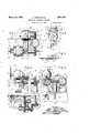
Fig. 1 is a top view of the improved cigarette cutofi;
Fig. 2 is a side elevatliron, partly in section,
Fi 3 is an end elevatfim of the cutofi as seen om the ri ht of Fig. 2'
Fig. 4 is an en elevation of the cutoff motor and blade as seen from the left of Fig. 2;
Fi 5 is a detailed elevation showing the relation of the cutoff blade, ledger plate and ci arette rod shown in Fig. 1;
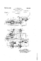
ig. 6 is a plan view of a modified form of a cutofi in accordance with the invention in which the knife tric motor rotating and vFig. 7 is a side elevation of the cutoff shown in Fig. 6 with the blade in cutting position.
In carrying the invention is provided a stationary means for continuously movin cigarette rod, and cutting mechanism inc udin a blade crossing thepath of the rod at sai means with sufficient speed to avoid interrupting the movement of the rod. In the best constructions, said mechanismincludes means for impartingorbital movement to said blade. Preferably, said mechanism includes an electric motor and means mounting said blade on the shaft of said motor. In the best constructions contemplated,vmeans are provided'for revolving said motor about a different axis than that of its shaft. In the best constructions also, said mechanism will include a blade is carried by an elec into effect, there enerator and a synchronous motor operatingin timed relation to the movement of said rod and means mounting the blade on the shaft of said motor. The means above referred to may be widely varied in'c'onstruction within the scope of the claims, machine selected to illustrate the invention is but one of many possible embodiments of the same. The invention, therefore, is not to be restricted to the precise details of the structure shown and described.
Referring to the drawings, the main drive one end of with a gear 12 which meshes with gear 13 mounted on a shaft 14 held by brackets 15 attached to the frame 16 of the cigarette maabout a vertical axis;
guiding a for the particular chine. On one end of the shaft 14 is mounted a bevel gear 17 which meshes with a bevel ggar 18 on vertical shaft 19 journalled in a aring 20 on the cigarette machine frame. The upper end of this shaft 19 carries a spiral gear 21 meshin with spiral ear 25 secured to one end of a orizontal sha t 26 journalled in a bearing 39 secured to the frame of the arms 30 to which the base of the motor 27 is bolted. The support 28 carries a counterweight 31 to balance the weight of the motor 27. v The blade arm 33 is secured to the shaft 32 of the motor and one end of this arm carries the cutoff blade 34.
As will be seen from an inspection of the dotted lines in Fig. 3 showing the path of the blade 34 operation of the motor and rotation thereof about the shaft 26 will impart to the. cutoff blade an epicyclic motion, i. e. a motion compounded of rotation about an'axis and a revolution or translation of this axis such that the blade is given movement about two different axes. As shown in Fig. 3, the movement of the axis of revolution of the blade causes the blade to periodically cross the path of the cigarette rod. In the form shown in Figs. 1 to 5, both movements are in the same plane ap roximately at right angles to the cigarette rod.
The cutting edge of the blade is ground to the proper curve and, as has already been described, is positioned so that it crosses the rod at a slight angle to perpendicular sufficient to compensate for the slight longitudinal movement of the cigarette rod during cutting. It is also'noted that the blade is made as narrow as is consistent with properly cutting the cigarette rod in order that the time during which the blade is crossing the path of the rod may be reduced tb a minimum.
In order that the blade may be rotated at high speed by motor 27 and at the same time may-be operated in exact timed relation to the rotation of the motor about shaft 26 and to the movement of the cigarette rod, this motor is made of the synchronous type and .is driven by an alternating generator 24. The synchronous motor and the alternating current generator, which is driven by a s ira gear 22 on the shaft 23 of the generator rom the gear 25, cooperates with the motor to operate the latter 1n accurately timed relation means of a support 28 clamped to the shaft by the clamp stud 29, and having the I chine.
, menses to those skilled in the art. It will, of course, be clear that in the device illustrated, the windings of the motor and the generator will be so related thatjhe motor rotates'exactly seven times as fast as the generator. The efiect then of the electrical synchronization of the motor with the drive of the cigarette machine through the generator 24, is to gear the shaft 32 to the drive of the cigarette ma- Indeed, gears may be used for this urpose, but the electrical connection is preerred because of its simplicity and its freedom from noise and vibration.
To conduct the alternating current from the generator 24 to the rotating motor, a horizontal arm 35 is provided, extending from the motor frame, and this frame carries insulated brushes 36 contacting with stationary metal rings 37 imbedded in the insulating sleeve 38 surrounding the bearing 39. The terminal wires 40 of the motor 27 are connected to the brushes 36, and the leads 41 of the generator are connected with contact rings 37; When the cigarette machine is running, the generator 24 driven by spiral gear 21 in step with the forward motion of the cigarette rod, supplies current to the synchronous motor 27 through the rings 37 and-the brushes 36, thereby rotating the blade 34 in exact step with the rotation of the shaft 26 and the movement of the cigarette rod.
In the cutoif illustrated, each time the motor 27 is in its lowermost position on the shaft 26, the blade 34 cuts through the cigarette rod C, which is fed through stationary guide 42 past the stationary ledger plate 43 on bracket 44. It is noted that the ledger plate 43 (Fig. 5) has, an oblique operating surface to cooperate with the angularly positioned edge of the cutoff. blade.
The modified form, as shown in Figs. 6 and 7. operates in the same way as'the cutoff already described, except that the synchronous motor in this form is rotated about a vertical instead of horizontal axis. The vertical shaft 19a is journalled in brackets extending from a pedestal 45 and-is driven from the horizontal shaft 140; by means of gears 46 and 47. Shaft 19a is provided with a gear 48 in mesh with the gear 49 driving the alternating current generator, which in this form is suspended from the underside of the frame 16 about the cigarette machine. The spiral gear 50 on the upper end of the shaft 19a meshes with gear 51 mounted on the horizontal shaft 52 journalled in a bearing ,53 on pedestal 45, and this shaft 52 has on its other end bevel gear 54, driving bevel gear 55 on the vertical shaft 56 journalled in bearing 57 in the pedestal 45.
This shaft 56 terminates in a disk 58 on the under face of which is secured the base of the synchronous motor 27. The upper with respect to the drive of the tte face of the projecting portion of the disk 58 machine ma manner which will be 0 vious carries the insulated contacting rings 59, to
which'are connected the leads 40 of the motor.
The bearing 57 has a radial arm 60 in which insulated bushings carry the stationary brushes 61 contacting. with the rings 59. The leads 41 o'f'the gene'ator are. connected to brushes 61. The horizontal shaft 32 of motor 27 carries. the arm 62- on the end of which the cutting blade 34 is mounted.
This blade, as already described in connection with the is likewise set to cross the path of the cigarette rod at an angle whichwill compensate for the slight movement of the rod during cutting. Since the blade in this arrangement crosses the cigarette rod twice in each revolution of the motor about the shaft, the ratio of the revolving movements of shafts 32 and 36 must be an odd integer, so that at its rearward crossing midway between cuts, the blade 34 is a half revolution away from its position when cutting, as shown from dotted lines in Fig. 7.
It will be seen that by substituting the electrical drive of the cigarette cutofi blade for a. mechanical drive. high speed revolvingof the blade is attained without the use of high speed gearing, thereby eliminating noise and harmful vibration.
What is claimed is:
1. In a cigarette cut-oil", the combination preferred form of the invention,
with stationary means for guiding a continuously moving cigarette rod, of coacting mechanism including a blade moving at con stant speed and in an epicyclic path crossing the path of the rod at said means with suflicient speed to avoid interrupting the movement of the rod, said mechanism including a rotating shaft and an alternating current generator driven from the cigarette machine drive, a synchronous motor fixed on said shaft, stationary metal rings. brushes supported by said motor and connected to the terminal wires thereof and engaging said rings, and leads connecting said rings to said generator.
2. In a cigarette cutoff, the combination with stationary means for guiding acontinuously moving cigarette rod, of coacting mechanism including a blade moving at constant speed and in an epicyclic path crossing the path of the rod at ment of the rod, said mechanism including said means with sufli-* Cient speed to id. interrupting the movea motor rotating about a horizontal axis above I the cigarette rod, cured to the shaft of said motor.
3. In a cigarette cutoff, the combination with stationary means for guiding a continuously moving cigarette rod, of coacting mechanism including a blade moving atconstant speed and crossing the path of the rod at said means with suilicient-speed to avoid interrupting the movement of the rod, said and saidblade being seconnected to said motor,
mechanism including a motor rotating on a vertical axis, and said blade being secured to the shaft of said motor.
4. In a cigarette cutoff, the combination with stationary means for guidin a continuously moving cigarette 'rod, 0 coacting mechanism including a blade moving at constant speed and crossing the path of the rod at said means with sufiicient speed to avoid interrupting the movement of the rod, said mechanism including a rotating vertical shaft and an alternating current generator driven from the cigarette machine drive, a synchronous motor fixed on said shaft, metal rings and stationary brushes engaging said rings and connected to said generator.
5. In a cigarette cutoff, the combination with stationary means for guiding a continuously moving cigarette rod, of coacting mechanism including a blade moving at constant speed and crossing the path of the rod at said means with sufficient speed to avoid interrupting the movement of the rod, said mechanism including an electric motor and means mounting said blade on the shaft of said motor. I
6. In a cigarette cutoff, the combination with stationar means for guiding a continuously moving cigarette rod, of coacting mechanism including a blade movin at constant s eed and crossing the path 0? the rod at sai means with suflicient speed to avoid interrupting the movement of the rod, said mechanism including an electric motor,
means mounting said blade on the shaft of said motor for orbital movement about the shaft as an axis, and means revolving said motor about a different axis.
7. In a cigarette cutoff, the combination with stationary means for guiding a continuousl moving cigarette rod, of coacting mec ianism including a blade moving at constant speed and crossin the path of the rod at said means with su cient speed to avoid interrupting the movement of the rod, said mechanism also including a generator and a synchronous motor operating in timed relation to the movement of said rod, and means mounting said blade on the shaft of said motor. 8. In a cigarette cutofif, the combination with stationary means for guiding a continuously moving cigarette rod, of coacting mechanism including a blade moving at constant speed and crossin the path of the rod at said means with en cient speed to avoid interrupting the movement of the rod, said mechanism also including-a revolving support, and a motor on said support having said blade secured to its shaft for orbital movement relative to said support.
9. In a cigarette cutoff, (the combination with stationary means for guiding a continuously moving cigarette rod, of coacting fimechanism including a blade movin at constant speed and crossfi the path 0 the rod at said means with s cient speed to avoid interrupting the movement of the rod, said blade havinglits cuttin edge positioned to cross the pat of the ro at a slight angle.
10. In a cigarette cutoff, the combination with stationary means for guiding a continuously" moving ci arette rod, of coacting mec anism inclu ing a blade movin at constant speed and crossing the path 0% the rod at sald means with suflicient speed to avoid interrupting the movement of the rod, said blade having its cutting edge positioned to cross the path of the rod at a slight angle, and said means including 8. led r plate having an oblique operating sur ace cooperating with the edge.
11. In a cigarette cutoff, the combination with stationary means for guiding a continuousl moving cigarette rod, of coacting mec anism including a blade movin at constant speed and crossin the path 0 the rod at said means with su cient speed to avoid interrupting the movement of the rod, said mechanism including a motor having said blade secured to its shaft, said blade being relativel narrow circumferentially as compared with its radius of movement.
12. In a continuous rod cigarette machine, a synchronous electric motor, a cutoff blade carried by the shaft of said motor, and means causing said motor to revolve said blade in' predetermined timed relation to the operation of the cigarette machine.
13. In a continuous rod cigarette machine, a synchronous electric motor, a cutoff blade carried by the shaft of said motor, and an alternating current enerator actuated by the cigarette machine rive and coacting with said motor to cause the same to revolve said blade in predetermined timed relation to the operation of the cigarette machine.
14. In a cigarette. cutoff, a synchronous electric motor, a flying blade carried b the shaft of said motor, means for revo ving said motor about a different axis than that of its shaft, and an alternating current generator coacting with said motor revolving means and said motor to cause said flying blade to move in redetermined timed relation to the revo ving movement of sai motor.
In testimony whereof, we have signed our names to this specification.
JOHN ALFRED STEIN.- WALDRON SHAPLEIGH MACDONALD.
Priority Applications (1)
| Application Number | Priority Date | Filing Date | Title |
|---|---|---|---|
| US334480A US1851334A (en) | 1929-01-23 | 1929-01-23 | Epicyclic cigarette cut off |
Applications Claiming Priority (1)
| Application Number | Priority Date | Filing Date | Title |
|---|---|---|---|
| US334480A US1851334A (en) | 1929-01-23 | 1929-01-23 | Epicyclic cigarette cut off |
Publications (1)
| Publication Number | Publication Date |
|---|---|
| US1851334A true US1851334A (en) | 1932-03-29 |
Family
ID=23307404
Family Applications (1)
| Application Number | Title | Priority Date | Filing Date |
|---|---|---|---|
| US334480A Expired - Lifetime US1851334A (en) | 1929-01-23 | 1929-01-23 | Epicyclic cigarette cut off |
Country Status (1)
| Country | Link |
|---|---|
| US (1) | US1851334A (en) |
Cited By (8)
| Publication number | Priority date | Publication date | Assignee | Title |
|---|---|---|---|---|
| US2825376A (en) * | 1953-11-26 | 1958-03-04 | Molins Machine Co Ltd | Apparatus for cutting a continuous length of material at intervals |
| US2839871A (en) * | 1955-05-26 | 1958-06-24 | Owens Illinois Glass Co | Glass rod and tube cutting mechanism |
| US2886083A (en) * | 1953-07-28 | 1959-05-12 | American Mach & Foundry | Cigarette rod cutter |
| US3353430A (en) * | 1965-08-24 | 1967-11-21 | American Mach & Foundry | High speed cigarette cutoff |
| US3356016A (en) * | 1966-04-06 | 1967-12-05 | Southwest Factories Inc | Automobile body disposal apparatus |
| US3426633A (en) * | 1965-01-12 | 1969-02-11 | Agfa Gevaert Ag | Sheet cutting device |
| US3604430A (en) * | 1969-11-07 | 1971-09-14 | Industrial Nucleonics Corp | Cigarette dense end measuring and controlling apparatus |
| US3604429A (en) * | 1969-10-03 | 1971-09-14 | Industrial Nucleonics Corp | Cigarette-dense-end-measuring method and apparatus |
-
1929
- 1929-01-23 US US334480A patent/US1851334A/en not_active Expired - Lifetime
Cited By (8)
| Publication number | Priority date | Publication date | Assignee | Title |
|---|---|---|---|---|
| US2886083A (en) * | 1953-07-28 | 1959-05-12 | American Mach & Foundry | Cigarette rod cutter |
| US2825376A (en) * | 1953-11-26 | 1958-03-04 | Molins Machine Co Ltd | Apparatus for cutting a continuous length of material at intervals |
| US2839871A (en) * | 1955-05-26 | 1958-06-24 | Owens Illinois Glass Co | Glass rod and tube cutting mechanism |
| US3426633A (en) * | 1965-01-12 | 1969-02-11 | Agfa Gevaert Ag | Sheet cutting device |
| US3353430A (en) * | 1965-08-24 | 1967-11-21 | American Mach & Foundry | High speed cigarette cutoff |
| US3356016A (en) * | 1966-04-06 | 1967-12-05 | Southwest Factories Inc | Automobile body disposal apparatus |
| US3604429A (en) * | 1969-10-03 | 1971-09-14 | Industrial Nucleonics Corp | Cigarette-dense-end-measuring method and apparatus |
| US3604430A (en) * | 1969-11-07 | 1971-09-14 | Industrial Nucleonics Corp | Cigarette dense end measuring and controlling apparatus |
Similar Documents
| Publication | Publication Date | Title |
|---|---|---|
| US1851334A (en) | Epicyclic cigarette cut off | |
| US3353430A (en) | High speed cigarette cutoff | |
| US1407033A (en) | Field-winding machine | |
| US3830126A (en) | Apparatus for severing wrapped tobacco filler rods or the like | |
| US3476002A (en) | Cut-off for cigarette rods or the like | |
| US1846942A (en) | Cut-off for high-speed cigarette machines | |
| US1984913A (en) | Flying shear | |
| US3728923A (en) | Cutting guide, notably for cigarette making machines | |
| US3863536A (en) | Cutting Guide for Machines for Producing Rods, Particularly for Cigarette Machines | |
| US2580959A (en) | Flying saw | |
| US2405204A (en) | Cutting device | |
| US2011645A (en) | Machine for perforating sheet material | |
| US1820142A (en) | Slitting device | |
| US1580809A (en) | Glass-severing apparatus | |
| US2711764A (en) | Cigarette cut-off mechanism | |
| US2886083A (en) | Cigarette rod cutter | |
| US1578505A (en) | Cigarette machine catcher | |
| US1729436A (en) | Cut-off for cigarette machines | |
| US2501288A (en) | Apparatus for making helical shaped candies | |
| US1848820A (en) | A corpoba | |
| US2438593A (en) | Welding method and apparatus | |
| US1616208A (en) | Cut-off mechanism for cigarette machines | |
| GB330142A (en) | Improvements in cut-off devices for cigarette-making machines | |
| US1647352A (en) | Cigarette-machine cut-off | |
| SU54651A1 (en) | Bar material viscous machine |