US1851333A - Ditch scraper - Google Patents
Ditch scraper Download PDFInfo
- Publication number
- US1851333A US1851333A US333277A US33327729A US1851333A US 1851333 A US1851333 A US 1851333A US 333277 A US333277 A US 333277A US 33327729 A US33327729 A US 33327729A US 1851333 A US1851333 A US 1851333A
- Authority
- US
- United States
- Prior art keywords
- scraper
- scrapers
- arms
- conveyor
- conveyors
- Prior art date
- Legal status (The legal status is an assumption and is not a legal conclusion. Google has not performed a legal analysis and makes no representation as to the accuracy of the status listed.)
- Expired - Lifetime
Links
- 230000033001 locomotion Effects 0.000 description 28
- 238000007790 scraping Methods 0.000 description 9
- 239000000463 material Substances 0.000 description 7
- 239000004020 conductor Substances 0.000 description 6
- 238000010276 construction Methods 0.000 description 2
- 230000003137 locomotive effect Effects 0.000 description 2
- 238000005096 rolling process Methods 0.000 description 2
- 230000008878 coupling Effects 0.000 description 1
- 238000010168 coupling process Methods 0.000 description 1
- 238000005859 coupling reaction Methods 0.000 description 1
- 230000010006 flight Effects 0.000 description 1
- 230000000977 initiatory effect Effects 0.000 description 1
- 230000001788 irregular Effects 0.000 description 1
- 238000012423 maintenance Methods 0.000 description 1
- 238000012986 modification Methods 0.000 description 1
- 230000004048 modification Effects 0.000 description 1
- 239000011435 rock Substances 0.000 description 1
Images
Classifications
-
- E—FIXED CONSTRUCTIONS
- E02—HYDRAULIC ENGINEERING; FOUNDATIONS; SOIL SHIFTING
- E02F—DREDGING; SOIL-SHIFTING
- E02F7/00—Equipment for conveying or separating excavated material
Definitions
- This invention relates generally to dirt scraping apparatus, and more specifically to an improved scraping machine adapted for use in the maintenance ofthe drainage ditches forming parts of railroad rights of Way, the
- Another important feature of the inven tion is to produce a scraping apparatus'of the type referred to having Widely extended portions adaptedto support the scrapers at the opposite sides of the apparatus, which Wide- 1y extended portions may be folded when not in use to permit passage of the scrapingapparatu's throng-l1 restricted places along the railroad right of way, and to permit transportation of the apparatus from place to place.
- the invention comprises the novel con struction, combination and arrangement of parts hereinafter more specifically described and illustrated in the accompanying drawings, wherein is shown the preferred embodiment or the invention.
- the invention c'omprehends' changes, variations and modifications which scraping apparatus.
- Fig.3 is a front elevation of my improved Fig. 4 is ance'nlarged fragmentary detail illustrating a deflector forming a part of the apparatus.
- A designates in'y ini'prov d scraping apparatus as a Whole, saidap pa ratus includingabed frame 1 Supported on trucks '2 ofthe type usually found'on railroad rolling stock.
- the trucks Zare provided with the usual wheels 3 which operate over therailroad rails l forming a part of the railroad road bed, which road bed at its ppposi'te sides is provided With the, usual drainage ditches D.
- the bed frame 1 of the apparatus A is provided with coupler elements 5 whereby said 'appa ratus may be coupled to other elem nts of railroad rolling stock for the purpose of 6on5. ducting the apparatus along the railroad right of Way.
- V, p 'f Arranged above the bed frame 1 of the ap paratus A is a beam 6 (Figs. 1 2 and 3), said beam being supported from the bed frame 1 by a plurality offsupportin'g elei'nent's which are approximately inverted .V-shape'd.
- One of these supporting elements, which is desig nated by the reference character 7, is located at the front end of the beam 6,'another there of, designated by the reference characte'rS,
- the major portion of the beam 6 inclines downwardly from the rear to the front portion of the apparatus, and the extreme rear portion 6 of the beam is approximately parallel with the top surface of the bed frame and overhangs the rear end of said bed frame, as shown in Fig. 1.
- the beam 6 is secured in any suitable manner to the supporting elements 7, 8, 9 and 10, and these supporting elements are suitably attached to the bed frame 1.
- a pair of supporting members 11 (Fig. 3), these supporting members being spaced apart from each other iaterally of the apparatus and each thereof being provided at its lower end with a hinge portion 12.
- Hingedly attached to the hinge portions 12 of the supporting members 11 are arms 13, said arms being extended in opposite directions from the members 11 as shown in Fig. 3, and being shaped so that the outer end portions thereof are in a lower plane than the inner end portions thereof when said arms are in their operative horizontal positions, as shown in Fig. 3.
- the arms 13 are preferably in the form of I-beams,'and each thereof adjacent to its outer end, supports a scraper 14 (Figs. land 5), said scrapers being so positioned on the arms 13 as to coincide vertically with the drainage ditches D at the opposite sides of the railroad road bed.
- the scrapers 14 comprise each a housing closed at its top, bottom and sides and open at its front and rear ends, the side walls of said housing at the front edge thereof being inclined from top to bottom, as shown in Fig. 1, and being provided at the lower portion of said front edge with sharpened scraping elements 15.
- the housings comprising the scrapers 14 extend rearwardly and inwardly with respect to the apparatus, as shown clearly in Fig. 2.
- each of the scrapers is open at its top and fixed to said scraper at said open top portion is an inverted U-shaped element 16 (Fig. 5), the side legs of said element being secured to the opposite side walls of the scraper and the intermediate leg thereof being ext-ended across the top of the scraper.
- each of the arms 13 adjacent to the scraper associated therewith is a pair of spaced brackets 19 which support for rotation a screw-threaded member 20.
- This screw-threaded member 20 is provided with a non-circular end portion 21 to which a suit able tool may be applied for the purpose of rotating said screw-threaded member.
- the associated hollow member 17 is provided with an internally screw-threaded element 22 arranged in fixed relation to said hollow member and the screw-threaded member 20 passes through said internally screw-threaded element 22.
- each of the scrapers 14 may be adjusted longitudinally of the arm 13 with which it is associated by merely rotating the associated screw-threaded member 20, the direction of movement of the scrapers depending on the direction of rotation of the screwthreaded members.
- each of which a downwardly inclined arm 24 is hingedly attached is secured to one of the horizontal arms 13.
- each inclined arm 24 is provided with a hinge joint 26 by which the two arm portions of which each arm 24 is comprised are hingedly joined together.
- the inclined arms 24 aid in supporting the scrapers 14 and it is obvious that said scrapers may be swung upwardly and inwardly with respect to the apparatus, the arms 13 swinging on the hinges at the inner ends thereof. and the arms 24'breaking upwardly at the hinge joints 26 and the arm portions thereof swinging on the hinges at the outer ends thereof.
- each of the inclined arms 24 is an adjusting means which comprises a member 27 rigidly :red to the bed frame of the apparatus.
- the members 27 are each provided with an internally threaded element 28 (Fig. 6) through which a screwthreaded rod 29 extends, said element being fixed to the associated member 27.
- Each of the screw-threaded rods 29 at one end there of is provided with a non-circular portion 30 and at its opposite end said screw-threaded rod projects beyond the adjacent element 28 and contacts with the adjacent inclined arm 24.
- each screw-threaded rod 29 has a collar 29 rigidly fixed thereon to guide same during movement thereof.
- each of the arms 32 is'attac'hed to one of the horizontal arms 13 whichsupport the scrapers 14.
- the arms 32 serve to brace the scrapers 14 when same are in use, and because of thehinge 'joints'at the rear ends of said arms 32'the forward portions thereofmay swing ⁇ upwardly when thescrafpersand the elements associated therewitha're moved to elevated positions.
- v l 1 Arranged at opposite sides of the apparatus is apaiir of dirt conveyors 33 which extend from the respective scrapers 14 to a point beyond the rearend of the apparatus.
- the conveyors converge toward each other as they extend from frontto rearof the appa'ratus ass-hown in'Fig. 2, and when viewed in side elevationas shown in Fig. 1 said con veyors are each inchnedupwardly from front Y to rear of the apparatus;
- Each conveyor 33 comprises apair of frame members 34- which are spaced apart in a transverse directlon and extend from one end of the conveyor to the 7 other thereof.
- the frame members 34 at the extreme rear ends of the conveyors 33 are arranged approximately horizo-ntally,-as shown in Fig. 1, and the frame members of each con veyor are joined by an end frame member 35 which is secured to the associated side frame 1 members by. "suitable gusset plates 36.
- each conveyor 33 Mounted for rotary motion in suitable bearings at the forward end of each conveyor 33-is a pulley 44, and mounted for rotary motionin suitable bearings at the rear of each conveyor is a relatively large pulley 45.
- 46 designatesan endless belt whichoperates over the ulleys 44 and .45 of each-conveyor 33, said belt being ofsubsta'ntial width as shown in Fig. 2.
- the endless belt 46 of.
- each conveyor passes around the pu11ey45 and "over a pulley 47' (F 1) arrangedad jaeent to said pulley 45, and from said pu l ley 4'? said endless belt asses beneath a belt tighteningpulley 48 which is arrangedfor adjustment toward and'away from the associated conveyor, whereby any slack which develops in the endlessbelt maybe taken up.
- a pulley 47' F 1 arrangedad jaeent to said pulley 45, and from said pu l ley 4'?
- said endless belt asses beneath a belt tighteningpulley 48 which is arrangedfor adjustment toward and'away from the associated conveyor, whereby any slack which develops in the endlessbelt maybe taken up.
- Mounted for rotation in suitable bearings spaced longitudinally of the conveyorsss are rolls 49 which serve to support the upper flights 0f the end less belts 46.
- the forward ends of the endless belts 46 are located immediately beneath the rear or discharge ends of the scrapers '14.
- each conveyor 33 Fixed to the shaft on which the pulley of each conveyor 33 ismounted is a sprocket wheel 53, and operating: over the sprocket wheels 45 and 53 0f each conveyor is a sprocket chain 54.
- Each of the shafts 51 is connected to a short transverse shaft 55 A (Fig. 2) suitably supported for rotation, by means of a universal joint 56, and each of said short transverse shafts 55 has a sprocket wheel 57 mounted thereon for rotation therewith.
- each of the short sh'afts58 Fixedly mounted on each of the short sh'afts58 is a sprocket wheel 59, said sprocket wheel being alined longitudinally of the apparatus with the respective sprocket wheels 57 on the shafts 55, and oper-' m ating over each pair of longitudinally alined sprocket sprocket wheels 57 and 59 is a chain 60.
- an axle of one of the trucks 2 of the apparatus has fixed thereto a sprocket wheel 61 over which a sprocket chain 62 operates.
- This sprocket chain also operates over a sprocket wheel 63 (Fig. 2) mounted ona shaft 64 extended transversely of the appara tus.
- the shaft 64 is. mounted for rotary motion in suitable bearings supported by the bed frame of the apparatus.
- 65 designates a pair of gear wheels which are keyed to the shaft 64 so that they will rotatewith said shaft while being permitted to move longitudinally with respect thereto, each of said gear wheels 65 having a pivoted operating lever 65 associated therewith by means of which said gear wheels may be shifted longitudinally of the shaft.
- gear wheels 66 are fixedly mounted on said shaft 58 at points outwardly of the gear wheels 66 is a pair of gear wheels 67.
- the gear wheels 67 are arranged in mesh with intermediate reversing pinions 68 which are mounted on short transverse shafts 69 supported for rotation in suitable bearings.
- the gear wheels 65 are shown in inoperative positions, but it is obvious that by moving the levers 65 said gear wheels may be shifted longitudinally of the shaft at to cause same to mesh either with the gear wheels 66 or the intermediate reversing pinions 67.
- each of the endless bolts 46 Located at the rear or discharge end of each of the endless bolts 46 is a deflector 70 which is pivoted at71 to suitable supporting elements 7 2 which depend from the frame members 34; of the respective conveyors.
- Each deflector comprises a flatblade which is of the approximate width of the associated endless belt and the pivot pin of each deflector has fixed there to an arm 7 3 (Fig. 1).
- each of the arms 7 8 Attached to the outer end of each of the arms 7 8 is a rod 74 which extends longitudinally of the apparatus, and is attached at its forward end to an operating lever 75, said operating lever being pivotally secured to the beam 6 at the point designated by the reference character 7
- Each of the operating levers 75 has associated with ita member 77 provided with an arcuate face 7 8 with which a suitable dctent cooperates to lock the operating lever in positions to which it has been adjusted.
- a car 79 adapted to receive the dirt or other material removed from the drainage ditches by the apparatus (Fig. 1), said car 79 being of ordinary construction and being disposed immediately beneath the deflectors 70.
- each of the conveyors 35 Associated with each of the conveyors 35 is a cable '80, by means of which the conveyors may be drawn upwardly so that the apparatus may be moved from place to place and may pass through restricted places along the railroad right of way.
- Each cable 80 is attached to the arm 13 associated with one of the scrapers 14, as shown in Fig. 7, and said cable passes upwardly from said arm to a sheave 81 over which the cable passes.
- the cables 80 pass from the sheaves 81 toward the rear of the apparatus, where each of said cables passes around a sheave 82 from the bottom to the top thereof and then passes to a sheave 83, around which it passes from top to bottom.
- Each cable 80 then passes around a sheave 84 from bottom to top thereof and passes then to a sheave 85, around which it passes from top to bottom.
- the sheaves 82 and 84 associated with each cable 80 are rotatably supported by a shaft carried by a yoke 86, and after passing around the sheave 85 as described, each cable passes to the associated yoke 86 to which the cable is rigidly attached, as shown at 87 in Fig. 7.
- 89 designates a pair of compressed air cylinders which are mounted on the bed frame of the apparatus, each of said cylinders having a reciprocatory piston mounted therein (not shown) with which a piston rod 90 is associated.
- the yokes 86 already referred to are located at the outer ends of the piston .1:
- 91 designates a compressed air reservoir, which is connected to the compressed air cylinders by suitable'conductors 92, passage of compressed air through said conductors being controlled by a valve 93 (Fig. 1).
- the scrapers 14 are arranged so that the lower forward portions thereof fit into the drainage ditches D, and when this is being accomplished the scrapers may be adjusted vertically by the screw-threaded members 29, or transversely with respect to the ditches by the screw-threaded members 20 (Figs. 3, 5 and 6). ⁇ Vhen the scrapers have been prop erly positioned with respect to the ditches D,
- the apparatus will be drawn forward by the locomotive or other movement imparting means to which the apparatus is attached.
- the operating levers 65 are operated to move the gear wheels 65 into mesh with the gear wheels 66, and therefore on forward movement of the apparatus the endless belts 46 will be driven so that the top flight thereof moves rearwa-rdly of the apparatus, as indicated by the arrows in Fig. 2.
- the scrapers Mare adjustable transversely of the apparatus with respect to the forward ends'of the endless belts, and to insure deposit of the dirt being scraped from the drainage ditches-on said endless belts, I'utilize the pivoted deflectors: 50;- These deflectors vare adjustableto difierent positions so that the dirt will pass from the scrapers onto the and less belts, even though the discharge ends of the scrapers are not in exact alinement with theendless belts.
- the upper edges of the deflectors 50 contact closely with the top walls 7 said deflectors in the of the scrapers. whereby friction will retain positions to which they have been adjusted.
- the scrapers 14, together withthe conveyors 33 may be folded upwardly and rearwardly.
- each associated scraper and conveyor. at either side of the apparatus may .be operated while the scraper and con veyor at the opposite :side thereof is elevated or is maintained inoperative, as each associated scraper and conveyor is operated indecomprise leaf springs
- leaf springs One of these leaf springs is associatedwith each of the scrapers 14:,said leaf spring being fixed atone of its ends to one of the arms 13 and the opposite end portion thereof being extended from said arm 13 and being in contact with the top wall of the associated scraper.
- Thevscrapers ll are suspendedfromthe screw-threaded members 20, and in the absence'of means .for' preventing such movement, contact ofthe forward edges ofthe scrapers with the ground whenthe apparatus is in motion would cause the scrapers to pivot rearwardly about the v screw-threaded members 20.
- the pressure of the springs acting against the topiwalls of thescrapers prevents-such movement of thescrap'ers unless the scrapers strike a some immovable object, such as a large rock,
- a ditch scraper comprising a portable apparatus adapted for attachmentto motive means movable along a railroad right of way, said apparatus including a scraper arranged to be extended into a drainage ditch at a side of said railroad right of way and being movable therethrough during movement of the apparatus, means for adjusting said scraper laterally of the apparatus, a con veyor for conducting material from said scraper to a point remote therefrom, and a deflector at the discharge end of said scraper for guiding the material discharged from said scraper onto said conveyor.
- a ditch scraper comprising a portable apparatus adapted for attachment to motive means movable along a railroad right of way, said apparatus including a scraper arranged tobe extended into a drainage ditch at a side of said railroad right of way and being movable therethrough during movement of the apparatus, means for adjusting said scraper laterally of the apparatus, a conveyor for conducting material from said scraper to a point remote therefrom, and a pivoted deflector at the discharge end of said scraper for guiding the material discharged from said scraper onto said conveyor.
- a ditch scraper comprising a portable apparatus adapted for attachment to motive means movable along a railroad right of way, said apparatus including a scraper arranged to be extended into a drainage ditch at a side of said railroad right of way and being movable therethrough during movement of the apparatus, means for adjusting said scraper laterally of the apparatus, a conveyor for conducting material from said scraper to a point remote therefrom, and a pair of pivoted deflectors at the discharge end of said scraper for guiding the material discharged from said scraper onto said conveyor.
- a ditch scraper comprising a portable apparatus adapted for attachment to motive means movable along a railroad right of way, said apparatus including a scraper arranged to be extended into a drainage ditch at a side of said railroad right of way and being movable therethrough during movement of the apparatus, a conveyor for conducting material from said scraper to a point remote therefrom, a support for said scraper, means whereby said scraper may be adjusted transversely of the apparatus, and yieldable means adapted to oppose pivotal movement of said scraper with respect to said support.
- a ditch scraper comprising a portable apparatus adapted for attachment to motive means movable along a railroad right of way, said apparatus including a scraper arranged to be extended into a drainage ditch at the side of said railroad right of way and being movable therethrough during movement of the apparatus, a conveyor for con- ,i
Landscapes
- Engineering & Computer Science (AREA)
- Mining & Mineral Resources (AREA)
- Civil Engineering (AREA)
- General Engineering & Computer Science (AREA)
- Structural Engineering (AREA)
- Soil Working Implements (AREA)
Description
March 29, 1932-. R. s. STEPHENS 1,851,333
DITCH SCRAPER Filed Jan. 18, 1929 3 Sheets-Sheet 1 DIT CH SCRAPER Filed Jan. 18, 1929 3 Sheets-Sheet 2 /Nl/EN 70B 2. 5. 57'EPHE/Y5 A TTOENEV March 29, 1932. R, 5, sTEPHENS 1,851,333
' DITCH SCRXPER Filed Jan. 18, 1929 3 Sheets-Sheet 3 .FfaJ
ATTORNEY Patented Mar. 29,1932
uuirea ear-Ares! PATENT Fries] BITCH SCRAPER Application filed January "18,, 1929; SerialNo. 333,277..
This invention relates generally to dirt scraping apparatus, and more specifically to an improved scraping machine adapted for use in the maintenance ofthe drainage ditches forming parts of railroad rights of Way, the
predominant object of the invention being to produce a portable apparatus of this type. which may be attached to a steam locomotive or other movement initiating means a and drawn along the right of way in a manner to cause the loose dirt and other matter which has accumulated in the drainage ditches to be removed therefrom.
' Prior to this invention the task of maintaining drainage ditches of railroad rights of Way free from accumulated matter has been a ery expensive one, due to the absence of suitable equipment which would perform the task eihciently in an economical manner. lnithe use of my improved apparatus, the drainage ditches at both sides of the right of way are simultaneously scraped and the gathered material resulting from s'uchfs'crap ingoperations is automatically carried away from the'scraping elements of the apparatus to a point remotetherefrom, where said inateri'al is deposited in a suitable receptacle, which referably is in the form of a dump car which travels along the right of Way With the scraping apparatus.
Another important feature of the inven tion is to produce a scraping apparatus'of the type referred to having Widely extended portions adaptedto support the scrapers at the opposite sides of the apparatus, which Wide- 1y extended portions may be folded when not in use to permit passage of the scrapingapparatu's throng-l1 restricted places along the railroad right of way, and to permit transportation of the apparatus from place to place.
With the forego-ing; and other objects in view, the invention comprises the novel con struction, combination and arrangement of parts hereinafter more specifically described and illustrated in the accompanying drawings, wherein is shown the preferred embodiment or the invention. However, it is tobe understood that the invention c'omprehends' changes, variations and modifications which scraping apparatus.
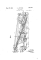
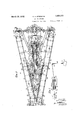
posits sides come within tiles-ca e of the claims hereunto appended. I i'sa side elevation f a scrapingappa ratus constructed in accordance With invention. 7 V Q 4 Fig. 2 is a plan viewer the apparatus illustrated in Fig. 1. i
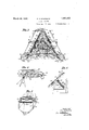
Fig.3 is a front elevation of my improved Fig. 4 is ance'nlarged fragmentary detail illustrating a deflector forming a part of the apparatus.
the scrapers-to tl iflere it In the drawings, A designates in'y ini'prov d scraping apparatus as a Whole, saidap pa ratus includingabed frame 1 Supported on trucks '2 ofthe type usually found'on railroad rolling stock. The trucks Zare provided with the usual wheels 3 which operate over therailroad rails l forming a part of the railroad road bed, which road bed at its ppposi'te sides is provided With the, usual drainage ditches D. At its front and rear ends the bed frame 1 of the apparatus A is provided with coupler elements 5 whereby said 'appa ratus may be coupled to other elem nts of railroad rolling stock for the purpose of 6on5. ducting the apparatus along the railroad right of Way. V, p 'f Arranged above the bed frame 1 of the ap paratus A is a beam 6 (Figs. 1 2 and 3), said beam being supported from the bed frame 1 by a plurality offsupportin'g elei'nent's which are approximately inverted .V-shape'd. One of these supporting elements, which is desig nated by the reference character 7, is located at the front end of the beam 6,'another there of, designated by the reference characte'rS,
positioned adjacent to the rear end of the beam 6, while a pair of said supporting-ale ments designated by the reference characters 9 and 10, respectively, are located intermediate of said supporting elements 7 and 8, as shown clearly in Fig. 1. The major portion of the beam 6 inclines downwardly from the rear to the front portion of the apparatus, and the extreme rear portion 6 of the beam is approximately parallel with the top surface of the bed frame and overhangs the rear end of said bed frame, as shown in Fig. 1. The beam 6 is secured in any suitable manner to the supporting elements 7, 8, 9 and 10, and these supporting elements are suitably attached to the bed frame 1.
Secured to and extended downwardly from the bed frame 1 of the apparatus A, at the front end thereof, is a pair of supporting members 11 (Fig. 3), these supporting members being spaced apart from each other iaterally of the apparatus and each thereof being provided at its lower end with a hinge portion 12. Hingedly attached to the hinge portions 12 of the supporting members 11 are arms 13, said arms being extended in opposite directions from the members 11 as shown in Fig. 3, and being shaped so that the outer end portions thereof are in a lower plane than the inner end portions thereof when said arms are in their operative horizontal positions, as shown in Fig. 3. The arms 13 are preferably in the form of I-beams,'and each thereof adjacent to its outer end, supports a scraper 14 (Figs. land 5), said scrapers being so positioned on the arms 13 as to coincide vertically with the drainage ditches D at the opposite sides of the railroad road bed.
' The scrapers 14 comprise each a housing closed at its top, bottom and sides and open at its front and rear ends, the side walls of said housing at the front edge thereof being inclined from top to bottom, as shown in Fig. 1, and being provided at the lower portion of said front edge with sharpened scraping elements 15. The housings comprising the scrapers 14 extend rearwardly and inwardly with respect to the apparatus, as shown clearly in Fig. 2. At the extreme forward portion thereof each of the scrapers is open at its top and fixed to said scraper at said open top portion is an inverted U-shaped element 16 (Fig. 5), the side legs of said element being secured to the opposite side walls of the scraper and the intermediate leg thereof being ext-ended across the top of the scraper. 17 designates hollow members open at their opposite ends, one of which is associated with the scraper, said. hollow members having the irregular cross-sectional shape shown in Fig. 1. The inverted U-shaped element 16 associated with the scraper with which a particular'hollow member 17 isassociated extends through said hollow member 17, and also the associated arm 13 extends loosely through said hollow member. The hollow member of each scraper is rigidly fixed to the inverted U-shaped element of said scraper, as shown in Fig. 5, the means of attachment shown in this view being the rivets 18.
Fixed to each of the arms 13 adjacent to the scraper associated therewith is a pair of spaced brackets 19 which support for rotation a screw-threaded member 20. This screw-threaded member 20 is provided with a non-circular end portion 21 to which a suit able tool may be applied for the purpose of rotating said screw-threaded member. The associated hollow member 17 is provided with an internally screw-threaded element 22 arranged in fixed relation to said hollow member and the screw-threaded member 20 passes through said internally screw-threaded element 22.
In View of the arrangement just described, it is obvious that each of the scrapers 14 may be adjusted longitudinally of the arm 13 with which it is associated by merely rotating the associated screw-threaded member 20, the direction of movement of the scrapers depending on the direction of rotation of the screwthreaded members.
Secured to the beam 6 at opposite sides thereof are hinge elements 23, to each of which a downwardly inclined arm 24 is hingedly attached. at its opposite end each of the arms hingedly attached to a hinge element 25 which is secured to one of the horizontal arms 13. Also intermediate of its opposite ends each inclined arm 24 is provided with a hinge joint 26 by which the two arm portions of which each arm 24 is comprised are hingedly joined together. The inclined arms 24 aid in supporting the scrapers 14 and it is obvious that said scrapers may be swung upwardly and inwardly with respect to the apparatus, the arms 13 swinging on the hinges at the inner ends thereof. and the arms 24'breaking upwardly at the hinge joints 26 and the arm portions thereof swinging on the hinges at the outer ends thereof.
Associated with each of the inclined arms 24 is an adjusting means which comprises a member 27 rigidly :red to the bed frame of the apparatus. The members 27 are each provided with an internally threaded element 28 (Fig. 6) through which a screwthreaded rod 29 extends, said element being fixed to the associated member 27. Each of the screw-threaded rods 29 at one end there of is provided with a non-circular portion 30 and at its opposite end said screw-threaded rod projects beyond the adjacent element 28 and contacts with the adjacent inclined arm 24. Also, each screw-threaded rod 29 has a collar 29 rigidly fixed thereon to guide same during movement thereof. It is obvious that by applying a tool to the non-circular end portions of the screw-threaded rods 29 and rotating same the lower portions of the arms 24 may be adjusted vertically to t ssue-as regulate the vertical. positions :of the scrapeach "of which an'arm3'2 is 'hingedly attached.
At the end of each of the arms 32, opposite to the end thereof which is attached to the asso-' ciated hinge element 31, said arm is'attac'hed to one of the horizontal arms 13 whichsupport the scrapers 14.. The arms 32 serve to brace the scrapers 14 when same are in use, and because of thehinge 'joints'at the rear ends of said arms 32'the forward portions thereofmay swing {upwardly when thescrafpersand the elements associated therewitha're moved to elevated positions. v l 1 Arranged at opposite sides of the apparatus is apaiir of dirt conveyors 33 which extend from the respective scrapers 14 to a point beyond the rearend of the apparatus.
The conveyors converge toward each other as they extend from frontto rearof the appa'ratus ass-hown in'Fig. 2, and when viewed in side elevationas shown in Fig. 1 said con veyors are each inchnedupwardly from front Y to rear of the apparatus; Each conveyor 33 comprises apair of frame members 34- which are spaced apart in a transverse directlon and extend from one end of the conveyor to the 7 other thereof. The frame members 34 at the extreme rear ends of the conveyors 33are arranged approximately horizo-ntally,-as shown in Fig. 1, and the frame members of each con veyor are joined by an end frame member 35 which is secured to the associated side frame 1 members by. "suitable gusset plates 36. Ex tended transversely of each; of'the conveyors 33 in a manner to secure the side frame members 34 together. is aplurality of beams37, 38 and 39. These beams, which are spaced longitudinally of theconveyors, extend in wardly beyond said conveyors and the beams 37 and 38 are turned upwardly at their inner; ends and are rigidly fixed at said inner ends to the. arms 32 already'referred to herein (Fig. 2). The inner end of the transverse beam 39associated with each conveyor 33 is hingedly attached toa hinge; element; 40
which is fixed to thesupporting element 10, as shown in Figs. 1 and 2. At theextreme rear end of the beam 6 'ofthe apparatus I rigidly secure a transverse bar 41 towhich is fixed at the opposite ends thereof a pair of hinge elements 42. The respective hinge elements42 have hingedly secured to them hinge elements .43 which are secured to the outer side frame members of the respective conveyors 33 whereby said conveyors are hingedly attached to said transverse bar 41.
Mounted for rotary motion in suitable bearings at the forward end of each conveyor 33-is a pulley 44, and mounted for rotary motionin suitable bearings at the rear of each conveyor is a relatively large pulley 45. 46 designatesan endless belt whichoperates over the ulleys 44 and .45 of each-conveyor 33, said belt being ofsubsta'ntial width as shown in Fig. 2. The endless belt 46 of.
each conveyor passes around the pu11ey45 and "over a pulley 47' (F 1) arrangedad jaeent to said pulley 45, and from said pu l ley 4'? said endless belt asses beneath a belt tighteningpulley 48 which is arrangedfor adjustment toward and'away from the associated conveyor, whereby any slack which develops in the endlessbelt maybe taken up. Mounted for rotation in suitable bearings spaced longitudinally of the conveyorsss are rolls 49 which serve to support the upper flights 0f the end less belts 46. As shownclearly in Figs. 1 and 2, the forward ends of the endless belts 46 are located immediately beneath the rear or discharge ends of the scrapers '14. Also, as'indicated by Fig. 2, each scraper has pivotally supported therein a pair of deflectors 5O, the function of'whichwill be hereinafter set forth. i
Mounted for rotation. in suitable bearings supported by the side frame members of each thereon; Fixed to the shaft on which the pulley of each conveyor 33 ismountedis a sprocket wheel 53, and operating: over the sprocket wheels 45 and 53 0f each conveyor is a sprocket chain 54. Each of the shafts 51 is connected to a short transverse shaft 55 A (Fig. 2) suitably supported for rotation, by means of a universal joint 56, and each of said short transverse shafts 55 has a sprocket wheel 57 mounted thereon for rotation therewith. 58 designates a second pair of short shafts which are mounted for rotation in suitable bearings, said shafts 58 being extended transversely of the apparatus and being alined with each other, also the respective short shafts 58 arealined longitudinally of .the'apparatus with theshort shafts 55, as
shown in F ig'. 2. Fixedly mounted on each of the short sh'afts58 is a sprocket wheel 59, said sprocket wheel being alined longitudinally of the apparatus with the respective sprocket wheels 57 on the shafts 55, and oper-' m ating over each pair of longitudinally alined sprocket sprocket wheels 57 and 59 is a chain 60.
By referring to Figs. 1 and 2,it will be noted that an axle of one of the trucks 2 of the apparatus has fixed thereto a sprocket wheel 61 over which a sprocket chain 62 operates. This sprocket chain also operates over a sprocket wheel 63 (Fig. 2) mounted ona shaft 64 extended transversely of the appara tus. The shaft 64 is. mounted for rotary motion in suitable bearings supported by the bed frame of the apparatus. 65 designates a pair of gear wheels which are keyed to the shaft 64 so that they will rotatewith said shaft while being permitted to move longitudinally with respect thereto, each of said gear wheels 65 having a pivoted operating lever 65 associated therewith by means of which said gear wheels may be shifted longitudinally of the shaft. 'Fixedly mounted on the shaft 58 is a pair of gear wheels 66 and fixedly mounted on said shaft 58 at points outwardly of the gear wheels 66 is a pair of gear wheels 67. The gear wheels 67 are arranged in mesh with intermediate reversing pinions 68 which are mounted on short transverse shafts 69 supported for rotation in suitable bearings. In Fig. 2 the gear wheels 65 are shown in inoperative positions, but it is obvious that by moving the levers 65 said gear wheels may be shifted longitudinally of the shaft at to cause same to mesh either with the gear wheels 66 or the intermediate reversing pinions 67.
In the operation of the apparatus, rotary motionis transmitted from the axle on which sprocket wheel 61 is mountedto the shaft 64 through the instrumentality of the sprocket chain 62. When the gear wheels 65 are in mesh with the gear wheels 66 it is plain that motion of the shaft 6a will be transmitted through said gear wheels to the shafts 58, which motion will in turn be transmitted from the shafts 58 to the shafts 55 by the sprocket chains 60. Motion of the shafts 55 will then be transmitted through the universal joints 56 to the shafts 51, thence to the sprocket wheels 53 through the instrumentality of the sprocket chains 5a, whereby the pulleys45 will be rotated to impart movement to the endless belts 46.
Located at the rear or discharge end of each of the endless bolts 46 is a deflector 70 which is pivoted at71 to suitable supporting elements 7 2 which depend from the frame members 34; of the respective conveyors. Each deflector comprises a flatblade which is of the approximate width of the associated endless belt and the pivot pin of each deflector has fixed there to an arm 7 3 (Fig. 1). Attached to the outer end of each of the arms 7 8 is a rod 74 which extends longitudinally of the apparatus, and is attached at its forward end to an operating lever 75, said operating lever being pivotally secured to the beam 6 at the point designated by the reference character 7 Each of the operating levers 75 has associated with ita member 77 provided with an arcuate face 7 8 with which a suitable dctent cooperates to lock the operating lever in positions to which it has been adjusted.
Attached to the apparatus A in the usual manner by coupling elements is a car 79 adapted to receive the dirt or other material removed from the drainage ditches by the apparatus (Fig. 1), said car 79 being of ordinary construction and being disposed immediately beneath the deflectors 70.
Associated with each of the conveyors 35 is a cable '80, by means of which the conveyors may be drawn upwardly so that the apparatus may be moved from place to place and may pass through restricted places along the railroad right of way. Each cable 80 is attached to the arm 13 associated with one of the scrapers 14, as shown in Fig. 7, and said cable passes upwardly from said arm to a sheave 81 over which the cable passes. The cables 80 pass from the sheaves 81 toward the rear of the apparatus, where each of said cables passes around a sheave 82 from the bottom to the top thereof and then passes to a sheave 83, around which it passes from top to bottom. Each cable 80 then passes around a sheave 84 from bottom to top thereof and passes then to a sheave 85, around which it passes from top to bottom. The sheaves 82 and 84 associated with each cable 80 are rotatably supported by a shaft carried by a yoke 86, and after passing around the sheave 85 as described, each cable passes to the associated yoke 86 to which the cable is rigidly attached, as shown at 87 in Fig. 7. The
sheaves 83 and 85 associated with each cable a;
are rotatably mounted on a shaft 88 suitably supported by the bed frame of the apparatus A.
89 designates a pair of compressed air cylinders which are mounted on the bed frame of the apparatus, each of said cylinders having a reciprocatory piston mounted therein (not shown) with which a piston rod 90 is associated. The yokes 86 already referred to are located at the outer ends of the piston .1:
In the use of my improved apparatus the scrapers 14 are arranged so that the lower forward portions thereof fit into the drainage ditches D, and when this is being accomplished the scrapers may be adjusted vertically by the screw-threaded members 29, or transversely with respect to the ditches by the screw-threaded members 20 (Figs. 3, 5 and 6). \Vhen the scrapers have been prop erly positioned with respect to the ditches D,
the apparatus will be drawn forward by the locomotive or other movement imparting means to which the apparatus is attached. Immediately before movement is imparted to the apparatus, the operating levers 65 are operated to move the gear wheels 65 into mesh with the gear wheels 66, and therefore on forward movement of the apparatus the endless belts 46 will be driven so that the top flight thereof moves rearwa-rdly of the apparatus, as indicated by the arrows in Fig. 2. With the endless belts operating as described, it is i obvious that dirt scraped from the drainage ditches D will pass upwardly and rearward-- ly through the scrapers 14 and said dirt will be deposited-on the endless belts46, "and as a result of the movement of said endless belts the dirt will be conveyed to thefrear of'the apparatus, where-it willjbe discharged'fro-m the endless conveyors into the car 7 9-which is attached tothef'apparatus. The dirt which- 7 is conveyed to the rear of, the-apparatus by the-conveyors e6 slides along the deflectors 70, as it is discharged from the endless belts,
and therefore by adjusting the positions of I thedeflectors by manipulation ofthe operating levers 7 5 the dirt discharged into the car 79 may be distributed therein. The scrapers Mare adjustable transversely of the apparatus with respect to the forward ends'of the endless belts, and to insure deposit of the dirt being scraped from the drainage ditches-on said endless belts, I'utilize the pivoted deflectors: 50;- These deflectors vare adjustableto difierent positions so that the dirt will pass from the scrapers onto the and less belts, even though the discharge ends of the scrapers are not in exact alinement with theendless belts. The upper edges of the deflectors 50 contact closely with the top walls 7 said deflectors in the of the scrapers. whereby friction will retain positions to which they have been adjusted.
It may be necessary, in the use of the appa- 4 ratus, to move same rearwardly for short distances, and to prevent the direction of movement of the endless belts 46 from being reversed when this is done,so that any dirt which may be on said endless belts would be carried forwardly, I employ the intermediate reversing pinions 68 already referred to.
When the apparatus is to be -moved rearwardly the operating levers 65'" will be moved to shift the gear wheels 65 into mesh with the intermediate pinions 68, whereby, in spite of the rearward movement of the apparatus, the endless belts will be operated in the direction indicated by the arrows in 2., I
When it is desired to transport the apparatus from place to place, or when it isnecessary for same to pass through restricted places along the railroad'right of way, the scrapers 14, together withthe conveyors 33, may be folded upwardly and rearwardly.
v This may be accomplished by .operatingthe compressed air controlling valve 93 to permit compressed air to pass into the air cylinders 89 in a manner to move the pistons therein rearwardly. This rearward movement of the pistons within the cylinders will result in like rearward movement of the yolres 86 asso-;
ciated with said pistons, and because the cables associated with the respective scrapers are secured to said yokes and to the arms 13, said arms will be moved upwardly on their hinges, in the manner already dey hinging [action will take place at the'universal scribed, to elevate the scrapers. The hinged arms 32 shown clearly in Fig. 2am attached to the arn1s'13, as already described,'=andthe conveyors 33 are attached to these arms 32,
by means of the members '37and 38, hence when the-terms 13 are raised to elevatethe scrapers 14 the conveyors 33 will be likewise elevated, said conveyors hinging at the hinge elements 31, 4O and42 shown in Fig. 2. Also,
move with theconveyors. It isplain, there fore,"that on introduction of compressed air. into the air cylinders 89 the-scrapers 14 and conveyors 33 will be elevated upwardly-and inwardly with respect tothe apparatus, substantially reducing the width ofsaid apparatus; I
It is obvious that the associated scraper and conveyor. at either side of the apparatus may .be operated while the scraper and con veyor at the opposite :side thereof is elevated or is maintained inoperative, as each associated scraper and conveyor is operated indecomprise leaf springs One of these leaf springs is associatedwith each of the scrapers 14:,said leaf spring being fixed atone of its ends to one of the arms 13 and the opposite end portion thereof being extended from said arm 13 and being in contact with the top wall of the associated scraper. Thevscrapers ll are suspendedfromthe screw-threaded members 20, and in the absence'of means .for' preventing such movement, contact ofthe forward edges ofthe scrapers with the ground whenthe apparatus is in motion would cause the scrapers to pivot rearwardly about the v screw-threaded members 20. However, the pressure of the springs acting against the topiwalls of thescrapers prevents-such movement of thescrap'ers unless the scrapers strike a some immovable object, such as a large rock,
and in this event the springs 95 will yield, permitting the scrapers to swing rearwardly a sufficient distance to pass over the obstructionh v lVhile throughout this specification Ihave stated that my improved apparatus is 'in:-
tended particularly for use in maintaining drainage ditches, it is obvious that theapparatus may be usedito digthe drainage ditches inthe first instance.- Also, I wish: to state, when 'I use the-term dirt herein I refer: to any material which maybe handled by the apparatus as a result of scraping or digging operations; Y
, I claim:
1. A ditch scraper comprising a portable apparatus adapted for attachmentto motive means movable along a railroad right of way, said apparatus including a scraper arranged to be extended into a drainage ditch at a side of said railroad right of way and being movable therethrough during movement of the apparatus, means for adjusting said scraper laterally of the apparatus, a con veyor for conducting material from said scraper to a point remote therefrom, and a deflector at the discharge end of said scraper for guiding the material discharged from said scraper onto said conveyor.
2. A ditch scraper comprising a portable apparatus adapted for attachment to motive means movable along a railroad right of way, said apparatus including a scraper arranged tobe extended into a drainage ditch at a side of said railroad right of way and being movable therethrough during movement of the apparatus, means for adjusting said scraper laterally of the apparatus, a conveyor for conducting material from said scraper to a point remote therefrom, and a pivoted deflector at the discharge end of said scraper for guiding the material discharged from said scraper onto said conveyor.
3. A ditch scraper comprising a portable apparatus adapted for attachment to motive means movable along a railroad right of way, said apparatus including a scraper arranged to be extended into a drainage ditch at a side of said railroad right of way and being movable therethrough during movement of the apparatus, means for adjusting said scraper laterally of the apparatus, a conveyor for conducting material from said scraper to a point remote therefrom, and a pair of pivoted deflectors at the discharge end of said scraper for guiding the material discharged from said scraper onto said conveyor.
4. A ditch scraper, comprising a portable apparatus adapted for attachment to motive means movable along a railroad right of way, said apparatus including a scraper arranged to be extended into a drainage ditch at a side of said railroad right of way and being movable therethrough during movement of the apparatus, a conveyor for conducting material from said scraper to a point remote therefrom, a support for said scraper, means whereby said scraper may be adjusted transversely of the apparatus, and yieldable means adapted to oppose pivotal movement of said scraper with respect to said support. v
5. A ditch scraper comprising a portable apparatus adapted for attachment to motive means movable along a railroad right of way, said apparatus including a scraper arranged to be extended into a drainage ditch at the side of said railroad right of way and being movable therethrough during movement of the apparatus, a conveyor for con- ,i
ducting material from said scraper to a point remote therefrom, a support for said scraper, means associated with said support for pivotally supporting said scraper, said means serving to adjust said scraper transversely of the apparatus, and means adapted to oppose pivotal movement of said scraper with respect to said support.
In testimony that I claim the foregoing I hereunto affix my signature.
ROBERT S. STEPHENS.
Priority Applications (1)
| Application Number | Priority Date | Filing Date | Title |
|---|---|---|---|
| US333277A US1851333A (en) | 1929-01-18 | 1929-01-18 | Ditch scraper |
Applications Claiming Priority (1)
| Application Number | Priority Date | Filing Date | Title |
|---|---|---|---|
| US333277A US1851333A (en) | 1929-01-18 | 1929-01-18 | Ditch scraper |
Publications (1)
| Publication Number | Publication Date |
|---|---|
| US1851333A true US1851333A (en) | 1932-03-29 |
Family
ID=23302103
Family Applications (1)
| Application Number | Title | Priority Date | Filing Date |
|---|---|---|---|
| US333277A Expired - Lifetime US1851333A (en) | 1929-01-18 | 1929-01-18 | Ditch scraper |
Country Status (1)
| Country | Link |
|---|---|
| US (1) | US1851333A (en) |
Cited By (1)
| Publication number | Priority date | Publication date | Assignee | Title |
|---|---|---|---|---|
| US3316666A (en) * | 1964-12-10 | 1967-05-02 | Speno International | Ballast cleaner |
-
1929
- 1929-01-18 US US333277A patent/US1851333A/en not_active Expired - Lifetime
Cited By (1)
| Publication number | Priority date | Publication date | Assignee | Title |
|---|---|---|---|---|
| US3316666A (en) * | 1964-12-10 | 1967-05-02 | Speno International | Ballast cleaner |
Similar Documents
| Publication | Publication Date | Title |
|---|---|---|
| EP0019434B1 (en) | A screening apparatus | |
| US2309712A (en) | Apparatus for handling ballast in railway roadbeds | |
| US1739624A (en) | Loading machine | |
| US1851333A (en) | Ditch scraper | |
| US2447571A (en) | Ditch paving machine | |
| US1269098A (en) | Road-making machine. | |
| US1512382A (en) | Portable loading and elevating machine | |
| US1625864A (en) | melin | |
| US2587092A (en) | Self-loading excavator | |
| US3222803A (en) | Ballast removing apparatus | |
| US1822051A (en) | Leveler | |
| US1855257A (en) | Portable box car loader | |
| US2599778A (en) | Trench excavator | |
| US2665506A (en) | Ballast plow and distributor | |
| US1268314A (en) | Grading-machine. | |
| US2055176A (en) | Material remover | |
| US1238497A (en) | Apparatus for leveling and tamping concrete road-beds. | |
| US1382266A (en) | Conveying apparatus | |
| US1869446A (en) | Road machine | |
| US1683382A (en) | Concrete-road machine | |
| US1273206A (en) | Ditching-machine. | |
| US1909882A (en) | Pipe coating machine | |
| US1920319A (en) | Subgrading machine | |
| US1766456A (en) | Road cleaner | |
| US1942034A (en) | Road building machine |