US1851327A - Method of and apparatus for sound recording - Google Patents
Method of and apparatus for sound recording Download PDFInfo
- Publication number
- US1851327A US1851327A US452503A US45250330A US1851327A US 1851327 A US1851327 A US 1851327A US 452503 A US452503 A US 452503A US 45250330 A US45250330 A US 45250330A US 1851327 A US1851327 A US 1851327A
- Authority
- US
- United States
- Prior art keywords
- sound
- cutter
- groove
- wave
- finishing
- Prior art date
- Legal status (The legal status is an assumption and is not a legal conclusion. Google has not performed a legal analysis and makes no representation as to the accuracy of the status listed.)
- Expired - Lifetime
Links
- 238000000034 method Methods 0.000 title description 13
- 238000004519 manufacturing process Methods 0.000 description 3
- 230000003111 delayed effect Effects 0.000 description 2
- 238000009499 grossing Methods 0.000 description 2
- 238000010276 construction Methods 0.000 description 1
- 230000000717 retained effect Effects 0.000 description 1
Images
Classifications
-
- G—PHYSICS
- G11—INFORMATION STORAGE
- G11B—INFORMATION STORAGE BASED ON RELATIVE MOVEMENT BETWEEN RECORD CARRIER AND TRANSDUCER
- G11B3/00—Recording by mechanical cutting, deforming or pressing, e.g. of grooves or pits; Reproducing by mechanical sensing; Record carriers therefor
Definitions
- the present invention relates broadly to sound recording and more especially to an apparatus and method for use in the manufacture of phonograph records.
- Another disadvantage is that the vibration of the cutting tool is resisted by the wax in making this heavy cut to such an extent as to slightly modify or distort the mechanical sound wave groove being cut.
- the present invention when adapted to electrically operated recording methods and machines, comprises the usual and well known.
- two cutters are provided, each of which are actuated by its own motive device which vibrates the cutter according to the tone wave being recorded. Since it is desirable that the forward or roughing cutter and the finishing cutter shall both operate on the same wave portion of the same tone groove, it is desirable to delay the operation of the finishing cutter so that it operates on exactly the same part of the tone wave for which the roughing cutter has already cut a rough groove. This may be accomplished by dividing the electrical circuit from the microphone and introducing a nondistortion delay circuit in the finishing cutters operating circuit.
- guiding means for the cutters are arranged on radial lines relative to the axis of the wax disc and these guiding means cause the roughing cutter and the finishing cutter to gradually approach each other as the spiral on the disc grows smaller. In this way the time-speed factor of the spiral is maintained constant so that the delay established for operation of the finishing cutter is proper throughout its zone of operations relative to the wax disc.
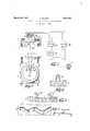
- Fig. 1 is a diagrammatic illustration of an electrical embodiment of the present invention.
- Fig. 2 is a diagrammatic illustration of the wax disc with the cutters thereover and diagrammatically shows the radial guides for the cutting tools.
- Fig. 4 is a front view showing the wax disc in section and illustrating the relation of the cutting tools when in a substantially silent portion of the sound groove.
- the wax disc 1 is mounted on suitable apparatus for rotating the disc at a constant speed and for moving the same on suitable trackways beneath the cutting tools, all of which mechanism is well known in the art.
- a forward cutter 2 is adapted to make a rough cut which takes out the majority of wax from the tone groove.
- a finishing cutter 4 follows in a groove cut by the roughing cutter and finishes the groove which the roughing cutter has laid out.
- the sound to be recorded is picked up by a microphone 5, the circuit of which leads to an amplifier 6, the output of which leads to the driving mechanism 7 for the cutter 1.
- the microphone circuit is divided and the division may take place after the circuit has passed the amplifier 6, or it may be divided before the circuit reaches amplifier 6, and the latter construction is illustrated in Fig. 1.
- the branch or shunt circuit from the microphone leads to a non-distortion delay circuit 8, and the output from the delay circuit leads to an amplifier 9 from which the output leads to the driving mechanism 10 for the finishing cutter 4. In this Way, both the cutters are operated from the microphone circuit.
- the two cutting tools may be retained in fixed position relative to each other.
- the common practice in the phonograph art is to maintain a constant rotative speed for the wax disc and therefore the actual surface speed of the disc beneath the cutting tool varies from the outside of the spiral to the inside thereof, and it therefore is necessary to either vary the delay circuit or change the relation of the distance between the cutting tools.
- the present disclosure diagrammat cally illus trates a simple way of correcting for this variability in speed by changing the spacing of the cutting tools, although it is to be understood that the speed correction may be made if desired by varying the delay circuit.
- guides 11 and 12 may be provided for the cutting tools 2 and 4:. These guides are radially disposed over the disc and are attached to the carriage 14 upon which the disc is mounted for translatory movement beneath the cutting tools, so that these guides have a translatory movement with the wax disc. It therefore will be observed that as the wax disc is moved transversely beneath the cutting tools, (which are relatively stationary to the translatory movement of the wax disc) the cutting tools are brought closer together by the guides 11 and 12 as the cutting tools approach the axis 15 of rotation of the disc 1, and in this way, the finishing tool his rotained at all times in the proper part of the groove 16 which has already been cut by the roughing tool 2 so that the finished groove 17 is a true tone groove of the sound being recorded.
- the roughing tool does the heavy work of taking out the major portion of the wax whereas the finishing tool is merely require to finish the groove in accordance with the true tone wave.
- the finishing tool has but a small amount of work to perform and consequently leaves a very smooth finished groove, which groove is accurately formed as to the sound variations because the finishing tool is not impeded by a deep heavy cut through the wax.
- the method of making a sound wave record comprising producing a sound track representation of said sound wave in rough on said record and then smoothing said representation and maintaining the characteristics of said sound wave when the smoothing operation is finished by re-recording the same sound wave on the said sound track.
- the method of recording sound waves comprising cutting an initial sound wave groove in the record and subsequently rerecording the said sound wave in the sound wave groove originally cut while maintaining the Wave form of the initial sound Wave groove.
- the method of recording sound waves comprising receiving the sound Waves in a translating apparatus adapted to convert said sound waves into electrical waves, dividing the electrical wave energy into separate channels, delaying the electrical waves in one channel, and utilizing the electrical energy of the channels to operate a plurality of sound recording means operative on different portions of a single sound record track.
- the method of recording sound waves upon a rotating record comprising recording the same sound wave a plurality of times on the same record and delaying the recording action of the later recordings to superimpose the samesound representation at difierent times on the same portion of the record.
- a device for recording sound comprising means for moving record material, a plurality of recording devices all operative on the same sound track, sound actuated means to operate said recording devices, and means to delay the operation of one of said devices: whereby a plurality of said devices operate to record the same sound in the same wave track on said record.
- a roughing cutter and a finishing cutter both operative in the same track, sound controlled means to operate the roughing cutter, sound controlled means to operate the finishing cutter, and delay means to delay the operation of the finishing cutter, so that the finishing cutter follows the Wave track cut by the roughing cutter.
- a roughing cutter and a finishing cutter both operative in the same track, sound controlled means to operate the roughing cutter, sound controlled means to operate the finishing cutter, delay means to delay the operation of the finishing cutter, and control means to cause the finishing cutter to follow the wave track cut by the roughing cutter throughout the said spiral groove.
- a device of the class described comprising a plurality of spaced apart cutting tools, sound wave controlled means to operate said cutting tools to engrave a tone wave, and delay means to control successively said cutting tools whereby all of said cutting tools follow a single wave track.
- a device of the class described comprising a roughing cutting tool and a finishing cutting tool, sound controlled means for operating said tools, and means to cause said finishing tool to finish and smooth the groove cut by said roughing tool and to maintain the wave form determined by said roughing tool.
Landscapes
- Milling Processes (AREA)
Description
I March 29, 1932. RAMSEY 1,851,327
METHOD OF AND APPARATUS FOR SOUND RECORDING Filed May 14, 1930 INVENTOR Patented Mar. 29, 1932 UNIT-ED STATES GEORGE RAMSEY, OF BROOKLYN, NEW YORK METHOD OF AND APPARATUS FOR SOUND RECORDING Application filed May 14,
The present invention relates broadly to sound recording and more especially to an apparatus and method for use in the manufacture of phonograph records.
Heretofore' in the art, it has been customary in making a phonograph record to translate the sound wave into a mechanical wave which is engraved as a sinuous spiral wave on a wax disc. The engraving operation has been performed by a cutting tool which cuts the full tone groove at one stroke. Where this occurs, the tool cuts the full width and full depth of the tone groove'and forces the wax to break out of the groove ahead of the cutter. This method has several disadvantages, one of which is that the wax in breaking away in front of the cutting tool leaves ragged edges on the side of the tone groove. Since the playing needle on the finished phonograph record,
in a lateral wave record, contacts contlnually with the side walls of the groove, these rough spots which are carried into the finished record distort the wave, wear the needle, and
-produce a scratchy tone in the sound reproduction. Another disadvantage is that the vibration of the cutting tool is resisted by the wax in making this heavy cut to such an extent as to slightly modify or distort the mechanical sound wave groove being cut.
The present invention overcomes the difficulties of the known prior art by providing two moving cutters or engraving tools, one of which takes out the majority of wax from the tone groove and the other of which finishes the tone groove to a true representation of the tone wave. By this apparatus and method the finishing tool does but little cutting, and since the major portion of the wax has been cleared from the groove by the forward cutter, the finishing cutter leaves a very smooth groove and the vibration of this finishing' cutter is not impeded by resistance of a substantial mass of wax.
The present invention is adapted especially for use with the modern electrical recording apparatus although it may be used with mechanical recording devices.
The present invention, when adapted to electrically operated recording methods and machines, comprises the usual and well known.
1930. Serial No. 452,503.
mechanism for rotating a disc of wax while it is being moved laterally beneath cutters. In the present invention, two cutters are provided, each of which are actuated by its own motive device which vibrates the cutter according to the tone wave being recorded. Since it is desirable that the forward or roughing cutter and the finishing cutter shall both operate on the same wave portion of the same tone groove, it is desirable to delay the operation of the finishing cutter so that it operates on exactly the same part of the tone wave for which the roughing cutter has already cut a rough groove. This may be accomplished by dividing the electrical circuit from the microphone and introducing a nondistortion delay circuit in the finishing cutters operating circuit. In view of the fact that the linear speed of a constantly rotating wax disc varies from the outside of the spiral to the inside thereof, guiding means for the cutters are arranged on radial lines relative to the axis of the wax disc and these guiding means cause the roughing cutter and the finishing cutter to gradually approach each other as the spiral on the disc grows smaller. In this way the time-speed factor of the spiral is maintained constant so that the delay established for operation of the finishing cutter is proper throughout its zone of operations relative to the wax disc.
It is realized that the present invention may be practiced by methods and apparatus other than those disclosed herewith and therefore it is to be understood that the disclosure is illustrative and not in the limiting sense.
Fig. 1 is a diagrammatic illustration of an electrical embodiment of the present invention.
Fig. 2 is a diagrammatic illustration of the wax disc with the cutters thereover and diagrammatically shows the radial guides for the cutting tools. v
Fig. Sis a detail side view section illus trating the action of the cutting tools.
Fig. 4: is a front view showing the wax disc in section and illustrating the relation of the cutting tools when in a substantially silent portion of the sound groove.
Fig.5 is a plan view showing the cutting tools operating in such manner that the finishing tool operates on the same part of a wave which has previously been engraved by the roughing tool.
In reference to the drawings, it is to be understood that these drawings are diagrammatic and that the present disclosure illustrates the invention by omitting details which are old in the art and which are well understood by those skilled in the art.
Referring now more especially to Fig. 1, the wax disc 1 is mounted on suitable apparatus for rotating the disc at a constant speed and for moving the same on suitable trackways beneath the cutting tools, all of which mechanism is well known in the art. A forward cutter 2 is adapted to make a rough cut which takes out the majority of wax from the tone groove. A finishing cutter 4 follows in a groove cut by the roughing cutter and finishes the groove which the roughing cutter has laid out.
The sound to be recorded is picked up by a microphone 5, the circuit of which leads to an amplifier 6, the output of which leads to the driving mechanism 7 for the cutter 1. The microphone circuit is divided and the division may take place after the circuit has passed the amplifier 6, or it may be divided before the circuit reaches amplifier 6, and the latter construction is illustrated in Fig. 1. The branch or shunt circuit from the microphone leads to a non-distortion delay circuit 8, and the output from the delay circuit leads to an amplifier 9 from which the output leads to the driving mechanism 10 for the finishing cutter 4. In this Way, both the cutters are operated from the microphone circuit. It is understood that suitable power is supplied to the circuits, as is well known in the art, and the operation of the finishing cutter is exactly the same as that of the forward cutter with the exception that the operation of the finishing cutter is delayed sufiiciently so that as the wax disc rotates, the finishing cutter operates on the correct portion of the groove which has already been made by the forward cutter.
Where the wax disc is rotated at a variable speed so that the linear speed beneath the cutting tool is constant, then the two cutting tools may be retained in fixed position relative to each other. The common practice in the phonograph art, however, is to maintain a constant rotative speed for the wax disc and therefore the actual surface speed of the disc beneath the cutting tool varies from the outside of the spiral to the inside thereof, and it therefore is necessary to either vary the delay circuit or change the relation of the distance between the cutting tools. The latter being the simpler problem, the present disclosure diagrammat cally illus trates a simple way of correcting for this variability in speed by changing the spacing of the cutting tools, although it is to be understood that the speed correction may be made if desired by varying the delay circuit. Assuming the delay circuit to be constant, then guides 11 and 12 may be provided for the cutting tools 2 and 4:. These guides are radially disposed over the disc and are attached to the carriage 14 upon which the disc is mounted for translatory movement beneath the cutting tools, so that these guides have a translatory movement with the wax disc. It therefore will be observed that as the wax disc is moved transversely beneath the cutting tools, (which are relatively stationary to the translatory movement of the wax disc) the cutting tools are brought closer together by the guides 11 and 12 as the cutting tools approach the axis 15 of rotation of the disc 1, and in this way, the finishing tool his rotained at all times in the proper part of the groove 16 which has already been cut by the roughing tool 2 so that the finished groove 17 is a true tone groove of the sound being recorded.
From the foregoing, it will be observed that the roughing tool does the heavy work of taking out the major portion of the wax whereas the finishing tool is merely require to finish the groove in accordance with the true tone wave. In this way, the finishing tool has but a small amount of work to perform and consequently leaves a very smooth finished groove, which groove is accurately formed as to the sound variations because the finishing tool is not impeded by a deep heavy cut through the wax.
Having described my invention, what I claim is 1. The method of recording sound waves on a wax record comprising controlling a roughing cutter by said sound wave to cut a rough sound groove in said wax and finishing said groove by another cutter controlled by said sound wave delayed.
2. The method of making a sound wave record comprising producing a sound track representation of said sound wave in rough on said record and then smoothing said representation and maintaining the characteristics of said sound wave when the smoothing operation is finished by re-recording the same sound wave on the said sound track.
3. The method of making a sound wave record comprising cutting an initial sound wave groove in said record and subsequently re-recording the same sound wave in the same groove and maintaining the characteris tics of the sound wave representations made by the initial cut.
4. The method of recording sound waves comprising cutting an initial sound wave groove in the record and subsequently rerecording the said sound wave in the sound wave groove originally cut while maintaining the Wave form of the initial sound Wave groove.
5. The method of recording sound waves comprising receiving the sound Waves in a translating apparatus adapted to convert said sound waves into electrical waves, dividing the electrical wave energy into separate channels, delaying the electrical waves in one channel, and utilizing the electrical energy of the channels to operate a plurality of sound recording means operative on different portions of a single sound record track.
6. The method of recording sound waves upon a rotating record comprising recording the same sound wave a plurality of times on the same record and delaying the recording action of the later recordings to superimpose the samesound representation at difierent times on the same portion of the record.
7. The method of recording a sound wave as a spiral upon a disc rotated at constant angular speed comprising engraving the same sound Wave at difi'erent times in the same spiral and moving the engraving members closer together as the spiral grows smaller to maintain a coordination between said engraving members throughout the length of the spiral.
8. A device for recording sound comprising means for moving record material, a plurality of recording devices all operative on the same sound track, sound actuated means to operate said recording devices, and means to delay the operation of one of said devices: whereby a plurality of said devices operate to record the same sound in the same wave track on said record.
9. In a device of the class described, the combination of a roughing cutter and a finishing cutter both operative in the same track, sound controlled means to operate the roughing cutter, sound controlled means to operate the finishing cutter, and delay means to delay the operation of the finishing cutter, so that the finishing cutter follows the Wave track cut by the roughing cutter.
10. In a device of the class described to cut a spiral tone groove in a disc record, the combination of a roughing cutter and a finishing cutter both operative in the same track, sound controlled means to operate the roughing cutter, sound controlled means to operate the finishing cutter, delay means to delay the operation of the finishing cutter, and control means to cause the finishing cutter to follow the wave track cut by the roughing cutter throughout the said spiral groove.
11. In a device of the class described, the combination of a plurality of successive cutting tools, sound controlled means to operate said cutting tools to record sound waves, and sound wave operated means to control said cutting tools to cause all of said tools to successively follow the same Wave track.
12. In a device of the class described comprising a plurality of spaced apart cutting tools, sound wave controlled means to operate said cutting tools to engrave a tone wave, and delay means to control successively said cutting tools whereby all of said cutting tools follow a single wave track.
18. In a device of the class described comprising a roughing cutting tool and a finishing cutting tool, sound controlled means for operating said tools, and means to cause said finishing tool to finish and smooth the groove cut by said roughing tool and to maintain the wave form determined by said roughing tool.
GEORGE RAMSEY.
Priority Applications (1)
| Application Number | Priority Date | Filing Date | Title |
|---|---|---|---|
| US452503A US1851327A (en) | 1930-05-14 | 1930-05-14 | Method of and apparatus for sound recording |
Applications Claiming Priority (1)
| Application Number | Priority Date | Filing Date | Title |
|---|---|---|---|
| US452503A US1851327A (en) | 1930-05-14 | 1930-05-14 | Method of and apparatus for sound recording |
Publications (1)
| Publication Number | Publication Date |
|---|---|
| US1851327A true US1851327A (en) | 1932-03-29 |
Family
ID=23796713
Family Applications (1)
| Application Number | Title | Priority Date | Filing Date |
|---|---|---|---|
| US452503A Expired - Lifetime US1851327A (en) | 1930-05-14 | 1930-05-14 | Method of and apparatus for sound recording |
Country Status (1)
| Country | Link |
|---|---|
| US (1) | US1851327A (en) |
Cited By (4)
| Publication number | Priority date | Publication date | Assignee | Title |
|---|---|---|---|---|
| US4248438A (en) * | 1978-03-18 | 1981-02-03 | Teldec-Telefunken-Decca Schallplatten Gmbh | Mechanical record cutting method |
| US4352973A (en) * | 1979-02-23 | 1982-10-05 | Crosfield Electronics Limited | Machine for simultaneously turning and laser engraving printing cylinders |
| US4918678A (en) * | 1977-12-12 | 1990-04-17 | Dolby Ray Milton | Disc reproducing system for compensating mechanical imperfections |
| US5964133A (en) * | 1997-06-26 | 1999-10-12 | Eastman Kodak Company | Method of precision finishing a vacuum imaging drum |
-
1930
- 1930-05-14 US US452503A patent/US1851327A/en not_active Expired - Lifetime
Cited By (4)
| Publication number | Priority date | Publication date | Assignee | Title |
|---|---|---|---|---|
| US4918678A (en) * | 1977-12-12 | 1990-04-17 | Dolby Ray Milton | Disc reproducing system for compensating mechanical imperfections |
| US4248438A (en) * | 1978-03-18 | 1981-02-03 | Teldec-Telefunken-Decca Schallplatten Gmbh | Mechanical record cutting method |
| US4352973A (en) * | 1979-02-23 | 1982-10-05 | Crosfield Electronics Limited | Machine for simultaneously turning and laser engraving printing cylinders |
| US5964133A (en) * | 1997-06-26 | 1999-10-12 | Eastman Kodak Company | Method of precision finishing a vacuum imaging drum |
Similar Documents
| Publication | Publication Date | Title |
|---|---|---|
| US2279018A (en) | Sound recording method and system | |
| US1851327A (en) | Method of and apparatus for sound recording | |
| GB1400274A (en) | Recording supports and reproduction apparatus | |
| GB1438306A (en) | Key cutting machines | |
| US938434A (en) | Cutter for punch-cutting machines. | |
| FR2368074A1 (en) | ELECTRICAL CONTROL CIRCUIT OF A CUTTING MACHINE FROM A MAGNETIC TAPE | |
| US732154A (en) | Machine-engraving. | |
| US2234320A (en) | Method of and means for edge cutting of sheet metal stock | |
| US965330A (en) | Sound-record-duplicating apparatus. | |
| US2340806A (en) | Sound recording apparatus | |
| US2668880A (en) | Apparatus for stereophonic sound-recording | |
| US2166079A (en) | Method and apparatus for the mechanical recording of sound oscillations | |
| US1357268A (en) | Machine for making phonographic records | |
| US1636149A (en) | Method of and apparatus for making sculptures | |
| US2012326A (en) | Automatic talking machine | |
| US1595976A (en) | Manufacture of wooden heels | |
| DE202594C (en) | ||
| US1855609A (en) | Phonograph record | |
| US1251907A (en) | Method of making styli, &c. | |
| US3964752A (en) | Methods and devices for recording, engraving and reproducing modulated information in tetraphony | |
| US2950116A (en) | Phonograph record | |
| US3527898A (en) | Signal compression or expansion sysstem using variable azimuth magnetic recording | |
| US671625A (en) | Phonograph. | |
| US941011A (en) | Apparatus for recording sound. | |
| US393465A (en) | Method of preparing phonograph recordtn |