US1851324A - Printing mechanism - Google Patents
Printing mechanism Download PDFInfo
- Publication number
- US1851324A US1851324A US468872A US46887230A US1851324A US 1851324 A US1851324 A US 1851324A US 468872 A US468872 A US 468872A US 46887230 A US46887230 A US 46887230A US 1851324 A US1851324 A US 1851324A
- Authority
- US
- United States
- Prior art keywords
- roller
- rollers
- bearing
- shaft
- pin
- Prior art date
- Legal status (The legal status is an assumption and is not a legal conclusion. Google has not performed a legal analysis and makes no representation as to the accuracy of the status listed.)
- Expired - Lifetime
Links
- 230000007246 mechanism Effects 0.000 title description 10
- 238000010276 construction Methods 0.000 description 11
- 238000004140 cleaning Methods 0.000 description 2
Images

Classifications
-
- B—PERFORMING OPERATIONS; TRANSPORTING
- B41—PRINTING; LINING MACHINES; TYPEWRITERS; STAMPS
- B41F—PRINTING MACHINES OR PRESSES
- B41F31/00—Inking arrangements or devices
- B41F31/30—Arrangements for tripping, lifting, adjusting, or removing inking rollers; Supports, bearings, or forks therefor
- B41F31/301—Devices for tripping and adjusting form rollers
-
- B—PERFORMING OPERATIONS; TRANSPORTING
- B41—PRINTING; LINING MACHINES; TYPEWRITERS; STAMPS
- B41F—PRINTING MACHINES OR PRESSES
- B41F13/00—Common details of rotary presses or machines
- B41F13/44—Arrangements to accommodate interchangeable cylinders of different sizes to enable machine to print on areas of different sizes
Definitions
- This invention relates to an improvement in printing apparatus, and has for one of its objects the provision of a construction whereby the form rollers are adjustable with respect to the type cylinder so as to enable the machine to be adjusted with the minimum of effort so as to accommodate type cylinders of difierent diameters.
- a further object of my invention is the provision of a construction wherein certain of the rollers employed in the machine are mounted in adjustable bearings, the bearings and the means for holding the rollers in their respective bearings being new and novel.
- Fig. 1 is a side elevational view of an embodiment of my invention
- Fig. 2 is a fragmentary plan view
- Fig. 3 is a sectional elevational View
- Figs.- 4 and 5 are details of the bearing construction.
- FIG. 2 and 3 designate vibrator rollers mounted on the shafts 4, 5 and 6, respectively.
- 7 and 8 designate distributor rider rollers and 9 and 10 designate transfer rollers in contact with the periphery of the vibrator roller 1 and 1n contact with the periphery of the vibrator rollers 2 and 3, respectively.
- the arrangement of these rollers is the usual arrange ment except that each of the rollers is mounted in a special bearing to be referred to hereinafter in detail, while the transfer rollers 9 and 10 are in addition adjustably mounted with respect to the roller 1. This is illustrated best in Fig. 3 where the roller 9 is shown on an enlarged scale with respect to the showing of Figs.
- bracket 11 is provided with a slotted attaching means shownat 12 and 13, whereby the roller 9 may be adjusted radially with respect to the roller 1.
- the mounting for the transfer roller 10 is the same as that described in connection with roller 9.
- rollers 14, 15, 16 and 17 designate form rollers a'construction whereby the rollers 14, 15, 16 and 17 may be adjusted with respect to the type cylinders so as to accommodate type cylinders of difierent diameters.
- the type cylinders are designated 22 and 28, respectively, these type cylinders being shown as of different diameters, it being understood of course that the two cylinders are not used simultaneously but that my invention provides an arrangement whereby the cylinder 22 may be removed and cylinder 23, which is of smaller diameter, substituted and the form rollers adjusted to correspond so that the form rollers will make the proper contact with the face of the type cylinders.
- the shafts carrying the form rollers are mounted in bearing arms at each end of each roller, these bearing arms being adjustable independently about the axes of the shafts 5 and 6.
- the form roller 14, for example, is mounted on bearing arms 24 adjacent each end of the roller, while the form roller'15 is mounted on similar bearing arms 25 adjacent each end of the roller.
- the arms 24 are adjustable about the axis of the shaft 5 independently of a similar adjustability of the bearing arms 25.
- the bearing arms 24 and 25 adjacent one end of the rollers 14 and 15 are mounted with a running fit on a sleeve 5 forming a bearing or journal for the shaft5.
- This sleeve is provided at one end with an integral collar 5, the other end being threaded and provided with a lock nut 5.
- By tightening the lock nut 5 the collar 5 is pulled against the frame 5 and the sleeve 5 and the adjusting arms will be held.together to hold the arms against movement.
- the other end of the shaft 5 is provided with a similar construction, there being a bearing arm 24 and a bearing arm 25 adjacent eacli end of the rollers 14 and 15.
- Each of the bearing arms 24 is provided with an extension 26 or ofl'set', each of the bearing arms 25 being provided with a similar offset 27.
- each of the extensions or ofl'sets 26 is a threaded adjusting rod 28, while threaded through each of the swivel blocks 27 on the outer end of the extensions 27 is a threaded adjusting rod 29.
- These rods are supported in the frame of the machine as shown at 30.
- Each of the adjusting rods 28 and 29 is provided with a circular rack 31 engaging a pinion 32 operated by handle 33, and on the outer end of each rod is an adjusting knob 34.
- the form rollers 16 and 17 are made adjustable by a similar mechanism except that this adjusting mechanism is disposed vertically of the machine as distinguished from the horizontal arrangement of the adjusting mechanism just described.
- this adjusting mechanism is disposed vertically of the machine as distinguished from the horizontal arrangement of the adjusting mechanism just described.
- extending vertically of the machine are pairs of adjusting rods 35 and 36.
- Each of these adjusting rods is rovide'd with a threaded connection to proections on the bearingarms 37 and 38 which arms are similar in construction to the hearing arms 24 and 25 and are similarly supported on the shaft 6.
- Each of these adjusting rods 35 and 36 is provided with a circular rack 39 engaging pinions 40, which pinions are operated by handles 41.
- On the outer end of each of the rods 35 and 36 is an adjusting knob 42 similar to the adjusting knobs 34 on the adjusting rods 28 and 29.
- rollers 7 8, 9, 10, 14, 15, 16 and 17 are all mounted in a special bearing. These bearings are similar in construction and are so designed as to make the rollers quickly removable and also 'so that the rollers may be adjusted slightly radially.
- Fig. 3 shows one of the bearings in detail, the bearing for the roller 14, which roller is provided with a squared shaft which in the case of the roller 14 has been designated 18.
- Each end of this shaft is mounted in an adjustable bearing block 43, each of these blocks being provided with an open sided rectangular slot 44 for the rece tion of the squared shaft of the roller.
- Eae of the blocks 43 is held in its supporting arm or bracket by a bolt 45 which passes through a slot in the arm or bracket and is adjustable radially of the roller carried by the block by means of an adjusting rod 46.
- roller shaft is held in the open sided slot or hearing 44 by a pin 47 mounted in the bearing block.
- the outer end of this pin is looped and when the shaft is in position in the slot 44 the in is turned so that the loop is in front of the shaft as shown in Fig. 3, the pin being held under tension by a spring 48. Gonsequer tly when it is desired to remove the shaft from its hearing block it is merely necessary to give the pin a half turn so as to bring the looped end away from the front of the shaft, the shaft thenbeing free for removal.
- this construction provides for cleaning the rollers without removing the same from their respective bearings.
- each of the blocks 43 is provided with a pin 49 which extends through the same and lies just behind the open sided slot or bearing 44.
- This pin is flattened at one side immediately behind the bearing 44 as shown at 51, this flattened portion being engaged by the flattened shaft 18, for instance.
- t at the spring mounting of the holding pin 47 permits of this movement of the roller shaft. It will also be apparent that upon swinging the member or pin 49 back to its original position, in which it is shown in Fig. 3, the roller 14 will be returned to its original position in its bearing under the action of the spring 48.
- rollers are adjustably mounted in their respective bearings whereby each of these rollers may be adjusted radially so that they may be accurately positioned with respect to their cooperating rolls or rollers.
- What I claim is 2- 1.
- a printing machine the combination of two pairs of form rollers adjacent the upper and lower faces of a type cylinder, horizontally disposed rack and pinion operated mechanism for effecting the independent adjustment of the rollers of the upper pair, and vertically disposed rack and pinion operated mechanism for effecting the independent adjustment of the rollers of the lower pair of rollers.
Landscapes
- Engineering & Computer Science (AREA)
- Mechanical Engineering (AREA)
- Rolls And Other Rotary Bodies (AREA)
Description
March 29, 1932. A. POTDEVIN PRINTING MECHANISM giled July 18. 2 Sheets-Sheet R. m m M m m T p WY M v1 1 Q "'4 T H 2" 1 AL. 1
March 29, 1932. A. POTDEVIN PRINTING MECHANISM Filed July 18 f 1950 2 Sheets-Sheet 2 z INVENOR.
A TTORN YS.
Patented Mar. 29, 1932 UNITED STATES PATENT OFFICE ADOIlIPH POTDEVIN, OF GARDEN CITY, NEW YORK, ASSIGNOR TO POTDEVIN MACHINE COMPANY, OF BROOKLYN, NEW YORK, A CORPORATION OF NEW YORK PRDN'TING MECHANISM Application filed July 18, 1930. Serial No. 468,872.
This invention relates to an improvement in printing apparatus, and has for one of its objects the provision of a construction whereby the form rollers are adjustable with respect to the type cylinder so as to enable the machine to be adjusted with the minimum of effort so as to accommodate type cylinders of difierent diameters.
A further object of my invention is the provision of a construction wherein certain of the rollers employed in the machine are mounted in adjustable bearings, the bearings and the means for holding the rollers in their respective bearings being new and novel.
In the drawings accompanying this application:
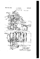
Fig. 1 is a side elevational view of an embodiment of my invention;
Fig. 2 is a fragmentary plan view;
Fig. 3 is a sectional elevational View; and
Figs.- 4 and 5 are details of the bearing construction.
Referring to the drawings in detailgl, 2 and 3 designate vibrator rollers mounted on the shafts 4, 5 and 6, respectively. 7 and 8 designate distributor rider rollers and 9 and 10 designate transfer rollers in contact with the periphery of the vibrator roller 1 and 1n contact with the periphery of the vibrator rollers 2 and 3, respectively. The arrangement of these rollers is the usual arrange ment except that each of the rollers is mounted in a special bearing to be referred to hereinafter in detail, while the transfer rollers 9 and 10 are in addition adjustably mounted with respect to the roller 1. This is illustrated best in Fig. 3 where the roller 9 is shown on an enlarged scale with respect to the showing of Figs. 1 and 2 and wherein it will be seen that the bracket 11 is provided with a slotted attaching means shownat 12 and 13, whereby the roller 9 may be adjusted radially with respect to the roller 1. The mounting for the transfer roller 10 is the same as that described in connection with roller 9.
14, 15, 16 and 17 designate form rollers a'construction whereby the rollers 14, 15, 16 and 17 may be adjusted with respect to the type cylinders so as to accommodate type cylinders of difierent diameters. The type cylinders are designated 22 and 28, respectively, these type cylinders being shown as of different diameters, it being understood of course that the two cylinders are not used simultaneously but that my invention provides an arrangement whereby the cylinder 22 may be removed and cylinder 23, which is of smaller diameter, substituted and the form rollers adjusted to correspond so that the form rollers will make the proper contact with the face of the type cylinders.
In order that this adjustment may be effected the shafts carrying the form rollers are mounted in bearing arms at each end of each roller, these bearing arms being adjustable independently about the axes of the shafts 5 and 6. The form roller 14, for example, is mounted on bearing arms 24 adjacent each end of the roller, while the form roller'15 is mounted on similar bearing arms 25 adjacent each end of the roller.
The arms 24 are adjustable about the axis of the shaft 5 independently of a similar adjustability of the bearing arms 25. To permit of this adjustment of these bearing arms the bearing arms 24 and 25 adjacent one end of the rollers 14 and 15 are mounted with a running fit on a sleeve 5 forming a bearing or journal for the shaft5. This sleeve is provided at one end with an integral collar 5, the other end being threaded and provided with a lock nut 5. By tightening the lock nut 5 the collar 5 is pulled against the frame 5 and the sleeve 5 and the adjusting arms will be held.together to hold the arms against movement. It is to be understood that the other end of the shaft 5 is provided with a similar construction, there being a bearing arm 24 and a bearing arm 25 adjacent eacli end of the rollers 14 and 15.
Each of the bearing arms 24 is provided with an extension 26 or ofl'set', each of the bearing arms 25 being provided with a similar offset 27.
Threaded through each of the swivel blocks 26 which are mounted in the outer nal movement of the adjusting rods.
end of each of the extensions or ofl'sets 26 is a threaded adjusting rod 28, while threaded through each of the swivel blocks 27 on the outer end of the extensions 27 is a threaded adjusting rod 29. These rods are supported in the frame of the machine as shown at 30. Each of the adjusting rods 28 and 29 is provided with a circular rack 31 engaging a pinion 32 operated by handle 33, and on the outer end of each rod is an adjusting knob 34.
It will be obvious that adjustment of the rods 28 will effect a rocking motion of thebearing arms 24 about the axis of the shaft 5 and hence an arcuate adjustment of the form roller 14. It will be obvious also that adjustment of the adjusting rods 29 will effeet a similar movement of the form roller 15, and that hence these two rollers are independently adjustable in an arc and with respect to the periphery of the type cylinder so that if, for example, the type cylinder 23 be substituted for the cylinder 22 the form rollers 14 and 15 may be brought into proper relation to the periphery of the type cylinder 23 without changing the adjustment between the transfer roller 2 and the form rollers.
The form rollers 16 and 17 are made adjustable by a similar mechanism except that this adjusting mechanism is disposed vertically of the machine as distinguished from the horizontal arrangement of the adjusting mechanism just described. In this connection it is to be noted that extending vertically of the machine are pairs of adjusting rods 35 and 36. Each of these adjusting rods is rovide'd with a threaded connection to proections on the bearingarms 37 and 38 which arms are similar in construction to the hearing arms 24 and 25 and are similarly supported on the shaft 6. Each of these adjusting rods 35 and 36 is provided with a circular rack 39 engaging pinions 40, which pinions are operated by handles 41. On the outer end of each of the rods 35 and 36 is an adjusting knob 42 similar to the adjusting knobs 34 on the adjusting rods 28 and 29.
It will be obvious from the foregoing that a rapid adjustment of the various adjusting rods may be efiectedby operating the levers 33 and 41 which through cross connecting rods 33 and 41" will operate the pinions at each end of the machine to effect longitudi- It will be understood also that a finer independent adjustment of these rods may be effected by rotation of the knobs 34 and 42.
As above mentioned the rollers 7 8, 9, 10, 14, 15, 16 and 17 are all mounted in a special bearing. These bearings are similar in construction and are so designed as to make the rollers quickly removable and also 'so that the rollers may be adjusted slightly radially. In this connection reference is made to Fig. 3 which shows one of the bearings in detail, the bearing for the roller 14, which roller is provided with a squared shaft which in the case of the roller 14 has been designated 18. Each end of this shaft is mounted in an adjustable bearing block 43, each of these blocks being provided with an open sided rectangular slot 44 for the rece tion of the squared shaft of the roller. Eae of the blocks 43 is held in its supporting arm or bracket by a bolt 45 which passes through a slot in the arm or bracket and is adjustable radially of the roller carried by the block by means of an adjusting rod 46.
Each end of the roller shaft is held in the open sided slot or hearing 44 by a pin 47 mounted in the bearing block. The outer end of this pin is looped and when the shaft is in position in the slot 44 the in is turned so that the loop is in front of the shaft as shown in Fig. 3, the pin being held under tension by a spring 48. Gonsequer tly when it is desired to remove the shaft from its hearing block it is merely necessary to give the pin a half turn so as to bring the looped end away from the front of the shaft, the shaft thenbeing free for removal.
In connection with the mountin of the rollers in their various bearings, this construction provides for cleaning the rollers without removing the same from their respective bearings.
It will be seen from Fig. 3 that each of the blocks 43 is provided with a pin 49 which extends through the same and lies just behind the open sided slot or bearing 44. This pin is flattened at one side immediately behind the bearing 44 as shown at 51, this flattened portion being engaged by the flattened shaft 18, for instance. When it is desired to clean the rollers without removing them from their bearings it is merely necessary to grasp the bent over portion50 of the pin 49 and to swing the pin a half turn so that the rounded portion of the pin engages the shaft 18 forcing or camming the same outwardly out of contact with its coo crating roller 2. It will be appreciated t at the spring mounting of the holding pin 47 permits of this movement of the roller shaft. It will also be apparent that upon swinging the member or pin 49 back to its original position, in which it is shown in Fig. 3, the roller 14 will be returned to its original position in its bearing under the action of the spring 48.
I have explained that the mountin for each of the rollers are the same and ence the description of the mounting for the roller 14 will sufiiee for the mountings of the other rollers.
It will be seen from the foregoing, therefore, that I have provided a construction in printing mechanisms wherein the rollers are adjustably mounted in their respective bearings whereby each of these rollers may be adjusted radially so that they may be accurately positioned with respect to their cooperating rolls or rollers.
It will be seen also that the mounting for these rollers is such that removal of the same from their bearings has been made easy and that the rollers may .be brought out of contact with their cooperating rollers for cleaning purposes, for example, without entirely removing the roller from its bearing.
It will be seen also that I have provided a construction wherein the form rollers may be adjusted in the arc of a circle, the rollers making up each pair of form rollers being adj ustable independently of each other so that with the greatest ease the rollers may be positioned properly with respect to a cooperating type cylinder, thereby adapting the machine for use with type cylinders of different diame- It will be understood that changes may be made in the details of construction above described within the purview of this invention.
. What I claim is 2- 1. In a printing machine the combination of two pairs of form rollers adjacent the upper and lower faces of a type cylinder, horizontally disposed rack and pinion operated mechanism for effecting the independent adjustment of the rollers of the upper pair, and vertically disposed rack and pinion operated mechanism for effecting the independent adjustment of the rollers of the lower pair of rollers.
2. In a printing machine the combination of a roller, a shaft for the roller, bearing blocks, an open bearing for said roller shaft in each block, and means carried by each bearing block and having movement relatively to said shaft into and out of operative position with respect to said roller shaft and its bearing, said means when in operative position maintaining the roller shaft in its bearing, and when out of operative position permit ting of the instantaneous removal of the roller shaft.
3. In a printing machine the combination of a roller, bearing supports, a bearing block in each support, each of said blocks being provided with an open bearing for the roller, a pin resiliently mounted in each block, said pin being rotatable to bring the head of the same in front of its corresponding bearing to maintain the roller in its bearings and rotatable out of such position to permit of the instantaneous removal of the roller from its bearings.
of a roller, bearin blocks each provided with an open bearing for the roller, a pin carried by each block adapted to be'rotated so as to bring its head in front of the corresponding bearing to prevent removal of the roller from its bearings, and a second rotatable pin carried by each of said blocks behind said bearings, said last mentioned pin being rotatable into engagement with the roller to lift the same out of its bearings.
6. In a printing machine the combination of a roller, a cooperating roller, bearing blocks for said first mentioned roller, yielding means for retaining said first mentioned roller in said bearing blocks, means for moving said first mentioned roller with respect to the bearing blocks out of contact with said cooperating roller and against the tension of said yielding means, said yielding means automatically restoring the roller to its original position in said bearing blocks and with respect to said cooperatingroller.
7. In a printing machine the combination of a roller, a roller shaft, a cooperating roller, bearing blocks mounting said roller shaft, and resiliently mounted means for holding the roller shaft in said bearin blocks, said means being movable indepen ently of said shaft into and out of operative position relatively thereto to permit of movement of the first mentioned roller out of contact with the cooperating roller.
This specification signed this 16th day of July, 1930.
ADOLPH POTDEVIN.
Priority Applications (1)
| Application Number | Priority Date | Filing Date | Title |
|---|---|---|---|
| US468872A US1851324A (en) | 1930-07-18 | 1930-07-18 | Printing mechanism |
Applications Claiming Priority (1)
| Application Number | Priority Date | Filing Date | Title |
|---|---|---|---|
| US468872A US1851324A (en) | 1930-07-18 | 1930-07-18 | Printing mechanism |
Publications (1)
| Publication Number | Publication Date |
|---|---|
| US1851324A true US1851324A (en) | 1932-03-29 |
Family
ID=23861584
Family Applications (1)
| Application Number | Title | Priority Date | Filing Date |
|---|---|---|---|
| US468872A Expired - Lifetime US1851324A (en) | 1930-07-18 | 1930-07-18 | Printing mechanism |
Country Status (1)
| Country | Link |
|---|---|
| US (1) | US1851324A (en) |
-
1930
- 1930-07-18 US US468872A patent/US1851324A/en not_active Expired - Lifetime
Similar Documents
| Publication | Publication Date | Title |
|---|---|---|
| US2751843A (en) | Self-adjusting form roll | |
| US3611924A (en) | Rotary offset printing press with cylinder interrupter | |
| US3034429A (en) | Printing press | |
| US1851324A (en) | Printing mechanism | |
| US2242514A (en) | Scoring knife | |
| US1975122A (en) | Feed roller mounting for tubing machines and the like | |
| US2372783A (en) | Adjustment for running register | |
| US1167004A (en) | Ball-marker. | |
| US2092461A (en) | Inking mechanism for rotary printing presses | |
| US2801584A (en) | Adjustable cylinder support for rotary printing mechanism | |
| US1933887A (en) | Late news printing machine | |
| US1627483A (en) | Inking mechanism for printing machinery | |
| US1574203A (en) | Apparatus for adjusting lithographic-machine damping rollers | |
| US425516A (en) | leayy | |
| US2335207A (en) | Grinding wheel truing apparatus | |
| US2177253A (en) | Rotary inking mechanism | |
| US2308107A (en) | Marking machine | |
| US1499456A (en) | Drill-press table | |
| US2818805A (en) | Roller socket mounting for printing machine ink mechanism | |
| DE512033C (en) | Device for adjusting the pressure in rotary rubber printing machines by means of eccentric cylinder bearings | |
| DE739494C (en) | Squeegee device for rotogravure printing machines | |
| US1869888A (en) | Locking and clamping mechanism for motion picture projector machine parts | |
| US1695793A (en) | Inking mechanism for intaglio-printing machines | |
| GB474029A (en) | Improvements in or relating to web guiding mechanism | |
| US1584578A (en) | Roller mounting for autographic registers |