US1851311A - Repeat mechanism for typewriters - Google Patents
Repeat mechanism for typewriters Download PDFInfo
- Publication number
- US1851311A US1851311A US83197A US8319726A US1851311A US 1851311 A US1851311 A US 1851311A US 83197 A US83197 A US 83197A US 8319726 A US8319726 A US 8319726A US 1851311 A US1851311 A US 1851311A
- Authority
- US
- United States
- Prior art keywords
- lever
- key
- type
- bar
- typewriter
- Prior art date
- Legal status (The legal status is an assumption and is not a legal conclusion. Google has not performed a legal analysis and makes no representation as to the accuracy of the status listed.)
- Expired - Lifetime
Links
- 230000000994 depressogenic effect Effects 0.000 description 4
- 238000010276 construction Methods 0.000 description 1
- 230000000694 effects Effects 0.000 description 1
Images

Classifications
-
- B—PERFORMING OPERATIONS; TRANSPORTING
- B41—PRINTING; LINING MACHINES; TYPEWRITERS; STAMPS
- B41J—TYPEWRITERS; SELECTIVE PRINTING MECHANISMS, i.e. MECHANISMS PRINTING OTHERWISE THAN FROM A FORME; CORRECTION OF TYPOGRAPHICAL ERRORS
- B41J25/00—Actions or mechanisms not otherwise provided for
- B41J25/02—Key actions for specified purposes
Definitions
- This invention relates to power driven typewriter mechanism and has for one of its objects the provision of means by which the type bar controlled by any particular key' may be caused to operate repeatedlywithout the necessity of repeating the depression of the key.
- a further object of the invention is to provide mechanism of the class named which shall be of improved construction and operation.
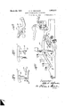
- FIG. 1 is a vertical sectional view of a portion of a typewriter having one embodiment of the present invention applied thereto
- Fig. 2 is a fragmentary top plan view of the mechanism shown in Fig. 1;
- Fig. 3 is a view similar to Fig. 1 showing a modified form of the invention.
- Figs. 4:, '5 and 6 are fragmentary views showing other modi ations.
- the numeral l0 designates a typewriter frame having the usual key levers 11 and type bars 12.
- a toothed cylinder 13 is journaled transversely of the typewriter frame and driven by any suitable power mechanism.
- Sublevers 14 are pivoted at 15 on a bar 16 extending across the frame 10. These sub" levers are connected at 17 to the type bars and responding actuator ismoved into engagement with the power drive 13 whereupon it 1s drawn forwardly to actuate the corresponding type bar.
- An adjustable stop screw 24 is provided in the path of the actuator by means of which the tooth 20 is disengaged from the power drive 13. In the usual operation of the machine the spring 23 will return the actuator to its initial position after such engagement.
- the present invention provides means for directing the actuator into re-engagement with the power drive 13 so that the operation of the type bar will be repeated as many times as desired.
- a lever 25 is pivotally mounted on a rod 26 which extends transversely of the frame of the typewriter.
- lever is provided with a slot 27 which engages the rod 26 and permits longitudinal sliding movement of the lever. Collars 28 are provided on each side of the lever to hold the lever against transverse movement.
- the rod 26 is carried by a bracket 30 secured to the typewriter frame by screws 31.
- a second rod 32 is carried on the bracket 30 and extends through an inclined slot 33 in the lever 25.
- a spring 34 normally draws the lever 25 forwardly.
- the forward end of the lever is provided with a key 38 for engagement by the operators finger. When the key is pressed rearwardly the slot 33 will slide upon the bar 32 and force the rear end of the lever 25 downwardly. This end is provided with a hook 40 whichoverlies a forward extension 41 on the actuator 19.
- the actuator 19 registers with a lug 42 carried on an arm 43 which is supported directly on one of the key levers.
- the arm 43 is clamped to the key lever b a screw 44 and may be readily removed y releasing the screw.
- the operation of the lug 42 is similar to that of the hook 40, except that the lug is operated by a de-' pression of the key lever corresponding to the type bar to be actuated instead of by pressing a special repeat key.
- the lug 43 is curved, as shown in the drawings, in order to avoid a cross-shaft 45 and a guide comb 46 for the key levers.
- a wire or rod 47 is bent upon itself at 48, the double portion of the rod being bent about the cross-bar 45 by which it is pivota lly supported.
- One end of the wire extends upwardly and is provided with a U-bend 49 open at its top for receiving the key lever 11.
- the other end of the wire extends rearwardly and is provided with a laterally bent portion 50 which overlies the extension 41 of the actuator 19.
- a contact bar 51 is secured directly to the extension 41 of the actuator 19 by means of a 6
- a bar 54 is secured to the key lever 11 by* set screw 52.
- the upper end ofthe bar 51 is provided with a head 53 which intercepts the ey lever 11 when the key leveris depressed. As long as the key lever is held down the head 53 will slide upon the under surface of the keylever and re-direct the actuator into engagement with the power drive after each operation ofthe type bar.- It-will be apparent that the contact bars 51 are easily applied to or removed from any actuator, as desired. Inithe form of the invention shown in Fig.
- a clip 55 which may be formed integrally with the bar and bent about the key lever to hold it in place.
- the bar extends between the lug 22 and the contact finger 21 and engages the upper face of the lug when the key lever is depressed. So long as the key lever is held in depressed position the lug 22 will re-en'gage the bar 54 after each operation of'the actuator 19 and slide along'the bar 54 to direct the actuator into reengagement with the power'drive.
- the repeat mechanism may be connected with other parts of the typewriter besides the type bars.
- the actuator 19 is shown as connected through rocker 57 and link 58 with the letter space operating link 59 for the es'capement not shown.
- the repeat device 43 is mounted on the space lever.
- I claim 2- 1.
- atypewriter having key levers, type bars, and power mechanism for actuating said type bars, of a repeat key lever for effecting automatic. repetition of the operation of a type bar, a pair of rods extending transversely of said typewriter upon which said repeat key lever is mounted, said key lever having slots therein for receiving said rods, one of said slots being inclined to produce pivotal movement' of said repeat key lever when said key lever is moved longitudinally.
- a typewriter having key levers and type bars, a power drive for actuating said type bars, means controlled by the key levers for selectively connecting the various type bars with said power drive, means for disconnecting each type bar from said power drive after a single operation thereof, and means for re-connecting said type bar with the power drive, said re-con' necting means being shiftable into position to cosipfirate with the difierent type bars.
Landscapes
- Impression-Transfer Materials And Handling Thereof (AREA)
Description
March 29, 1932. o. A. HOKANSON ,3
' REPEAT MECHANISM FOR TYPEWRITERS Filed Jan. 23, 1926 2 Sheets-Sheet, 1
March 1932. o, HQKANSQN 1,851,311
" REPEAT MECHANISM FOR TYPEWRITERS 2 Sheets-Sheet 2 Filed Jan. 23, 1926 Patented Mar. 29, 1932 UNITED STATES PATENT; OFFICE.
v OTTO A. HOKANSON, OF WOODSTOCK, ILLINOIS, ASSIGNOR 'I'O WOODSTOOi TYPEWRITER COMPANY, OF WOODSTOCK, ILLINOIS, A CORPORATION OF ILLINOIS urma Mechanism FOR 'r rnwmrnns Application filed January 23, 1926. Serial No. 83,197.
This invention relates to power driven typewriter mechanism and has for one of its objects the provision of means by which the type bar controlled by any particular key' may be caused to operate repeatedlywithout the necessity of repeating the depression of the key.
A further object of the invention is to provide mechanism of the class named which shall be of improved construction and operation.
The invention is exemplified in the combination and arrangement of parts shown in the, accompanying drawings and described in the following specification, and it is more particularly pointed out in the appended claims.
In the drawings Fig. 1 is a vertical sectional view of a portion of a typewriter having one embodiment of the present invention applied thereto Fig. 2 is a fragmentary top plan view of the mechanism shown in Fig. 1;
Fig. 3 is a view similar to Fig. 1 showing a modified form of the invention; and
Figs. 4:, '5 and 6 are fragmentary views showing other modi ations.
The invention is illustrated as applied to the Woodstock Electrite typewriter of the .kind shown in my prior application, Serial No.'732,615, but it will be understood that the invention is not limited to any particular make of typewriter, except as set forth in the appended claims.
The numeral l0 designates a typewriter frame having the usual key levers 11 and type bars 12. A toothed cylinder 13 is journaled transversely of the typewriter frame and driven by any suitable power mechanism. Sublevers 14 are pivoted at 15 on a bar 16 extending across the frame 10. These sub" levers are connected at 17 to the type bars and responding actuator ismoved into engagement with the power drive 13 whereupon it 1s drawn forwardly to actuate the corresponding type bar. An adjustable stop screw 24 is provided in the path of the actuator by means of which the tooth 20 is disengaged from the power drive 13. In the usual operation of the machine the spring 23 will return the actuator to its initial position after such engagement. The present invention, however, provides means for directing the actuator into re-engagement with the power drive 13 so that the operation of the type bar will be repeated as many times as desired. To accomplish this result a lever 25 is pivotally mounted on a rod 26 which extends transversely of the frame of the typewriter. The
lever is provided with a slot 27 which engages the rod 26 and permits longitudinal sliding movement of the lever. Collars 28 are provided on each side of the lever to hold the lever against transverse movement. The rod 26 is carried by a bracket 30 secured to the typewriter frame by screws 31. A second rod 32 is carried on the bracket 30 and extends through an inclined slot 33 in the lever 25. A spring 34 normally draws the lever 25 forwardly. The forward end of the lever is provided with a key 38 for engagement by the operators finger. When the key is pressed rearwardly the slot 33 will slide upon the bar 32 and force the rear end of the lever 25 downwardly. This end is provided with a hook 40 whichoverlies a forward extension 41 on the actuator 19. The downward movement of the hook 40 will move the actuator into engagement with the power drive 13 and cause the type bar to be operated. As long as the lever 25 is held in its rearward position the hook 40 will remain in position to intercept the actuator on its return movement and re-direct it into engagement with the power drive. It will thus be seen that so long as the key 38 is pressed inwardly the particular type bar with which the key is connected will continue to provided with as many repeat keys as desired or the single key, as shown in the drawings, may be readily shifted to co-operate with operate repeatedly. The typewriter may be any type bar by merely loosening the collars 28 and shifting the lever into registration with the actuator for the particular type bar.
In the form of the invention shown in Fig.- 3, the actuator 19 registers with a lug 42 carried on an arm 43 which is supported directly on one of the key levers. The arm 43 is clamped to the key lever b a screw 44 and may be readily removed y releasing the screw. It will be apparent that the operation of the lug 42 is similar to that of the hook 40, except that the lug is operated by a de-' pression of the key lever corresponding to the type bar to be actuated instead of by pressing a special repeat key. The lug 43 is curved, as shown in the drawings, in order to avoid a cross-shaft 45 and a guide comb 46 for the key levers.
In the form of the invention shown in Fig. 4, a wire or rod 47 is bent upon itself at 48, the double portion of the rod being bent about the cross-bar 45 by which it is pivota lly supported. One end of the wire extends upwardly and is provided with a U-bend 49 open at its top for receiving the key lever 11. The other end of the wire extends rearwardly and is provided with a laterally bent portion 50 which overlies the extension 41 of the actuator 19. It will be apparent that when the key lever 11 is depressed the wire 47 will be swung downwardly about the bar 45 as a pivot and will operate on the actuator 19 to effect repeated operation of the type bar in the same manner as the hook 40 shown in Fig. 1. This form of repeat mechanism may be readily shifted from one key lever to the other by sliding it lon itudinally on the rod 45. It will, of course, be necessary to release it from the key lever 11 and the actuator 41 to permit lateral sliding movement.
v In the form of the invention shown in Fig. 5, a contact bar 51 is secured directly to the extension 41 of the actuator 19 by means of a 6, a bar 54 is secured to the key lever 11 by* set screw 52. The upper end ofthe bar 51 is provided with a head 53 which intercepts the ey lever 11 when the key leveris depressed. As long as the key lever is held down the head 53 will slide upon the under surface of the keylever and re-direct the actuator into engagement with the power drive after each operation ofthe type bar.- It-will be apparent that the contact bars 51 are easily applied to or removed from any actuator, as desired. Inithe form of the invention shown in Fig.
means of a clip 55 which may be formed integrally with the bar and bent about the key lever to hold it in place. The bar extends between the lug 22 and the contact finger 21 and engages the upper face of the lug when the key lever is depressed. So long as the key lever is held in depressed position the lug 22 will re-en'gage the bar 54 after each operation of'the actuator 19 and slide along'the bar 54 to direct the actuator into reengagement with the power'drive.
The repeat mechanism may be connected with other parts of the typewriter besides the type bars. In Fig. 3 the actuator 19 is shown as connected through rocker 57 and link 58 with the letter space operating link 59 for the es'capement not shown. The repeat device 43 is mounted on the space lever.-
I claim 2- 1. The combination with a typewriter hav ing key levers and type bars, of a power device for actuating said type bars, means controlled by said key levers for connecting said power device with said type bars, means said type' bars after each operation of a type bar, and means operable at the will of the operator for automatically re-c'onnecting said power device and type bars after each operation of a type bar, said last-named means being shiftable for co-operation with different type bars.
2. The combination with atypewriter having key levers and type bars, of a power device for operating said type bars, actuators controlled by said key levers for connecting said power device with said type bars, means for disconnecting said actuators from said power device after each operation thereof, a separate lever independent of said key levers and having a shifting portion thereof movable into the path of said actuators to redirect said actuators into engagement with said power device, and a key for controlling said lever.
3. The combination with a typewriter having key levers and type' bars, of a power device for operating said type bar's, actuators for connecting said power device with said type bars, a lever movable into position to direct said actuators into re-engagement with said power device, and a pivot rod for said lever extending transversely of said typewriter, said lever being shiftable longitudinally of said pivot rod into position to co-operate with different-actuators.
The combination with atypewriter having key levers, type bars, and power mechanism for actuating said type bars, of a repeat key lever for effecting automatic. repetition of the operation of a type bar, a pair of rods extending transversely of said typewriter upon which said repeat key lever is mounted, said key lever having slots therein for receiving said rods, one of said slots being inclined to produce pivotal movement' of said repeat key lever when said key lever is moved longitudinally.
. 5. The combination with a typewriter havlng key levers, type bars, a power 'drive for said type bars, and actuators for connecting said power drive with said type .bars of repeat mechanism comprising a lever having a pair of slots therein, transverse rods extending through said slots, one of said slots being incline to impart pivotal movement to sald lever when sald lever is moved longitudinally, a key on said lever, a spring or holding said lever in inactive position, and means on said lever for engaging said actuators to produce repeated eration thereof when said key is depresse said lever being movable transversely of said typewriter along said rods into position to co-operate with difierent actuators.
6. In combination, a typewriter having key levers and type bars, a power drive for actuating said type bars, means controlled by the key levers for selectively connecting the various type bars with said power drive, means for disconnecting each type bar from said power drive after a single operation thereof, and means for re-connecting said type bar with the power drive, said re-con' necting means being shiftable into position to cosipfirate with the difierent type bars.
7 e combination with a ty ewriter having key levers and type bars, 0 a power device for operating said type bars, actuators controlled by said key levers for connecting said power device with said type bars, means for disconnectingsaid actuators from sai power device after each operation thereof, and means operable independent of said key levers and movable into the path of said actuators to redirect said actuators into enga ement with the power device.
testimony whereof I have signed my name to this specification on this 18th day of January, A. D. 1926.
OTTO A HOKANSON.
Priority Applications (1)
| Application Number | Priority Date | Filing Date | Title |
|---|---|---|---|
| US83197A US1851311A (en) | 1926-01-23 | 1926-01-23 | Repeat mechanism for typewriters |
Applications Claiming Priority (1)
| Application Number | Priority Date | Filing Date | Title |
|---|---|---|---|
| US83197A US1851311A (en) | 1926-01-23 | 1926-01-23 | Repeat mechanism for typewriters |
Publications (1)
| Publication Number | Publication Date |
|---|---|
| US1851311A true US1851311A (en) | 1932-03-29 |
Family
ID=22176793
Family Applications (1)
| Application Number | Title | Priority Date | Filing Date |
|---|---|---|---|
| US83197A Expired - Lifetime US1851311A (en) | 1926-01-23 | 1926-01-23 | Repeat mechanism for typewriters |
Country Status (1)
| Country | Link |
|---|---|
| US (1) | US1851311A (en) |
Cited By (3)
| Publication number | Priority date | Publication date | Assignee | Title |
|---|---|---|---|---|
| US2633964A (en) * | 1949-06-28 | 1953-04-07 | Keyboard controlled margin stop adjustment | |
| US3339695A (en) * | 1966-07-22 | 1967-09-05 | Ibm | Repeat mechanism for printing device |
| US3511352A (en) * | 1968-11-25 | 1970-05-12 | George B Greene | Automatic bar typewriters and the like having roll-cam type drive mechanisms |
-
1926
- 1926-01-23 US US83197A patent/US1851311A/en not_active Expired - Lifetime
Cited By (4)
| Publication number | Priority date | Publication date | Assignee | Title |
|---|---|---|---|---|
| US2633964A (en) * | 1949-06-28 | 1953-04-07 | Keyboard controlled margin stop adjustment | |
| US3339695A (en) * | 1966-07-22 | 1967-09-05 | Ibm | Repeat mechanism for printing device |
| DE1611444B1 (en) * | 1966-07-22 | 1971-06-09 | Ibm | DEVICE FOR CONTINUOUS STOP FOR POWER-DRIVEN WRITING MACHINERY AND SIMILAR MACHINERY |
| US3511352A (en) * | 1968-11-25 | 1970-05-12 | George B Greene | Automatic bar typewriters and the like having roll-cam type drive mechanisms |
Similar Documents
| Publication | Publication Date | Title |
|---|---|---|
| US1851311A (en) | Repeat mechanism for typewriters | |
| US2831558A (en) | Variable proportional letter feed mechanism | |
| US1614475A (en) | Power-actuated typewriter | |
| US3342295A (en) | Repeat action mechanism for power operated typewriters | |
| US1929975A (en) | Repeat mechanism for typewriters | |
| US1950762A (en) | Typewriting machine | |
| US1177943A (en) | Type-writing machine. | |
| US2474741A (en) | Power-operated typing mechanism for typewriters or like machines | |
| US1478600A (en) | Silent-key typewriter attachment | |
| US2310717A (en) | Typewriting machine | |
| US2757774A (en) | Impression regulating control for power driven typewriters | |
| US2521478A (en) | Power-actuated typewriter | |
| US1873406A (en) | Repeat mechanism for typewriters | |
| US2535358A (en) | Typewriter tabulator stop mechanism | |
| US1734728A (en) | Manual and power-operated typewriter | |
| US1433112A (en) | barr and e | |
| US1308980A (en) | Jhabtiit blodgett | |
| US1937047A (en) | Typewriting machine | |
| US992263A (en) | Type-writing machine. | |
| US2069298A (en) | Typewriting machine | |
| US1494716A (en) | Typewriting machine | |
| US1356157A (en) | Typewriting-machine | |
| US1873441A (en) | Repeat mechanism for typewriters | |
| US1398321A (en) | Typewriting-machine | |
| US1769625A (en) | Automatic typewriter |