US1851310A - Machine tool - Google Patents
Machine tool Download PDFInfo
- Publication number
- US1851310A US1851310A US253444A US25344428A US1851310A US 1851310 A US1851310 A US 1851310A US 253444 A US253444 A US 253444A US 25344428 A US25344428 A US 25344428A US 1851310 A US1851310 A US 1851310A
- Authority
- US
- United States
- Prior art keywords
- machine tool
- operators
- machine
- operator
- assembly
- Prior art date
- Legal status (The legal status is an assumption and is not a legal conclusion. Google has not performed a legal analysis and makes no representation as to the accuracy of the status listed.)
- Expired - Lifetime
Links
- 238000010276 construction Methods 0.000 description 8
- 238000000034 method Methods 0.000 description 5
- 238000003754 machining Methods 0.000 description 3
- 238000004519 manufacturing process Methods 0.000 description 3
- 240000002804 Calluna vulgaris Species 0.000 description 1
- 230000000712 assembly Effects 0.000 description 1
- 238000000429 assembly Methods 0.000 description 1
- 238000004140 cleaning Methods 0.000 description 1
- 239000002173 cutting fluid Substances 0.000 description 1
- 230000003247 decreasing effect Effects 0.000 description 1
- 239000000314 lubricant Substances 0.000 description 1
- 239000002184 metal Substances 0.000 description 1
- 230000000750 progressive effect Effects 0.000 description 1
Images

Classifications
-
- B—PERFORMING OPERATIONS; TRANSPORTING
- B23—MACHINE TOOLS; METAL-WORKING NOT OTHERWISE PROVIDED FOR
- B23Q—DETAILS, COMPONENTS, OR ACCESSORIES FOR MACHINE TOOLS, e.g. ARRANGEMENTS FOR COPYING OR CONTROLLING; MACHINE TOOLS IN GENERAL CHARACTERISED BY THE CONSTRUCTION OF PARTICULAR DETAILS OR COMPONENTS; COMBINATIONS OR ASSOCIATIONS OF METAL-WORKING MACHINES, NOT DIRECTED TO A PARTICULAR RESULT
- B23Q37/00—Metal-working machines, or constructional combinations thereof, built-up from units designed so that at least some of the units can form parts of different machines or combinations; Units therefor in so far as the feature of interchangeability is important
-
- B—PERFORMING OPERATIONS; TRANSPORTING
- B23—MACHINE TOOLS; METAL-WORKING NOT OTHERWISE PROVIDED FOR
- B23B—TURNING; BORING
- B23B39/00—General-purpose boring or drilling machines or devices; Sets of boring and/or drilling machines
- B23B39/16—Drilling machines with a plurality of working-spindles; Drilling automatons
-
- Y—GENERAL TAGGING OF NEW TECHNOLOGICAL DEVELOPMENTS; GENERAL TAGGING OF CROSS-SECTIONAL TECHNOLOGIES SPANNING OVER SEVERAL SECTIONS OF THE IPC; TECHNICAL SUBJECTS COVERED BY FORMER USPC CROSS-REFERENCE ART COLLECTIONS [XRACs] AND DIGESTS
- Y10—TECHNICAL SUBJECTS COVERED BY FORMER USPC
- Y10T—TECHNICAL SUBJECTS COVERED BY FORMER US CLASSIFICATION
- Y10T409/00—Gear cutting, milling, or planing
- Y10T409/30—Milling
- Y10T409/30868—Work support
-
- Y—GENERAL TAGGING OF NEW TECHNOLOGICAL DEVELOPMENTS; GENERAL TAGGING OF CROSS-SECTIONAL TECHNOLOGIES SPANNING OVER SEVERAL SECTIONS OF THE IPC; TECHNICAL SUBJECTS COVERED BY FORMER USPC CROSS-REFERENCE ART COLLECTIONS [XRACs] AND DIGESTS
- Y10—TECHNICAL SUBJECTS COVERED BY FORMER USPC
- Y10T—TECHNICAL SUBJECTS COVERED BY FORMER US CLASSIFICATION
- Y10T409/00—Gear cutting, milling, or planing
- Y10T409/30—Milling
- Y10T409/309576—Machine frame
Definitions
- This invention relates to improvements in machine tools, and particularly to an improved grouping or arrangement in a single apparatus, of a plurality of machine tools for related processes.
- An object of this invention is the creation of apparatus of improved adaptability for the machining and processing of related parts, such as the parts of small electric machines or the like, usually manufactured in quantities.
- the present invention attains an important object in increased production, by reducing the time required to perform a given number of operations, and by reducing the effort and fatigue to the operator.
- the present invention may be embodied in a simple and durable assembly of apparatus, adaptable by its arrangement to a great variety of operations.
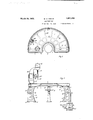
- Fig. 1 is a perspective view of the table and the machine tools thereon, showing a particular arrangement of the various machine tools about the operators chair;
- Fig. 2 is a plan view of the table; Fig.
- 3 is a side elevation of the table and the operators chair.
- the machine comprises a stationary, substantially semi-circular table top 1.
- Rib sections 2 substantially as shown in Fig. 2, are provided beneath the finished surface of the table top 1.
- At the center and along the front edge of top 1,' is formed a semi-circular recess 3 of suflicient depth and width partly to surround, and at the same time to allow unrestricted manual movement to an operator, and to permit free rotation of the operators chair
- the chair 4 is preferably of the swivel type, with the seat threaded into the base to provide an adjustment for height. It will be seen that the recess 3 and the chair 4, will each determine a fixed location for the operator, and serve definitely to station the operator in this location.
- a beaded edge 5 which forms one of the walls of a trough 6 for collecting any lubricant and cutting compound, and draining it to a catch basin, (not shown).
- a gradual, backward sloping portion 7 is formed, which eliminates any possible interference of the recess with the operators movements.
- the above described table top is supported on legs 8, three such legs being shown in Figs. 1 and 3, but it will be understood that any number of legs may be used in order to provide a substantial and rigid construction. Also, it will be understood that these legs may be cast or formed as integral parts of the table top, instead of being formed separately, as shown.
- legs 8 are attached rigidly to the tabletop 1 by means of tap bolts 9, or any suitable fastenings. Provisions for bolt supports are found on the upper flange portions 10 of each leg, which correspond with bosses 11 beneath the table, located substantially as shown in dotted lines in Fig. 2. Suitable drilled or cored holes are provided in the flange, and corresponding tapped holes are located in the bosses. A rigid and adjustable attachment is secured by this fastening means. Each leg is designed and constructed in a manner to combine the necessary qualities of strength and lightness. Flange portions 12 are connected to rib sections 13 and an open section 13.
- the inner flange portion 14 of the leg preferably presents a convex outer surface to allow greater freedom of movement for the operators legs.
- the lower flange is provided with lugs 15 suitably drilled in a manner (not shown), to secure the entire assembly upon the floor.
- lugs 15 suitably drilled in a manner (not shown), to secure the entire assembly upon the floor.
- boss 16 there is formed in the upper flange 10, a boss 16 cored out to permit the entrance of an electric conduit, or the like.
- Support base blocks 17 one for each of the machines, are positioned substantially equidistantly from the operators chair, as shown more clearly in Figs. 1 and 2. It will be understood that these blocks may be cast or formed integrally with the legs and table, but it is preferred that they are separate therefrom and rigidly attached thereto. By a suitable arrangement of slots. (not shown) in the table top, the positions of blocks 17 and hence of the machines, may be changed relative to each other and to the operator.
- Each block 17 is substantially square in cross section with cored out portions 18 and cored or drilled holes 19. Corresponding holes are drilled in the table top and in the motor supports 20, to provide means for securing the assembly to the table by means of bolts 21.
- Each drill assembly comprises a motor support 20, which may be rigidly but adjustably attached, as above stated, in the manner of blocks 17.
- the motor support has attached thereto a motor 22, driving a drill spindle 23 and a chuck 24. which in turn carries a drill 25.
- Also slidably attached to the support and the drill spindle is the adjustment or control portion 26.
- Each machine or drill has a separate motor and control.
- the electrical connections for each motor are provided from main lead 27. which enters through a core hole in the table leg, as pointed out above.
- Suitable opening 28 (as shown in Fig. permit the passage of the leads through the table, and thence they pass through the cored portion 18 of each base block.
- the leads pass through the cored out opening in the motor support 20, thence to the motor. All electrical connections are thus concealed and out of the way of the work.
- a. small arbor press 29 suitable for assembly work, when required.
- a horizontal multiple spindle drill 30 which may be for hand feed work.
- a horizontal motor 31 furnishes power for the spindle drill 30, and has a lead connection 3:2.
- An air hose or its equivalent 33 may be fitted to the table for cleaning the work and the machines.
- the described arrangement and construction is such that many successive operations on one or more parts or assemblies may be performed, quence of machine tools, the work may progress from one machine tool to the next, without needless lost motion of the operator.
- suitable jigs and fixtures for and further, by a suitable seholding the work, it is possible to swing the an arrangement of tools in a unit construction such as the above, is of great value, as conducive to a saving of time and production efficiency, since the operator has facilities for performing more work, with less fatigue, in a given time interval.
- the construction and arrangement described above as an example of this invention is particularly suited for machining small, light parts of such articles as small electric machines.
- the assembly may be either enlarged or reduced in size, or altered as to the number of separate processes, and may be modified for either machine or assembly work alone, or to combine various machining and assembly facilities, as in the pres ent example. While I have shown the different machines placed in the sequence of their use, this sequence may be varied in any manner as dictated by the nature and size of the work to be done.
- An assembly of machine tools for related se. uential processes including a semi-circular table of unitary construction and disposed in a horizontal plane, a pluarlity of tool-supporting members ad ust-ably mounted on the table, individually driven machine tool units, and an individual prime mover for driving each of said units, carried on said supports, the supports and units being arranged on radial lines and equidistant from a common manipulative location or station, the table being recessed on one side to accommodate an operator and the recess being only of such an area as substantially to establish the operators station at a substantially uniform distance from each of the machine tool units, and individual manual controls for the several prime movers and units, all of said controls being disposed Within a horizontal radial distance, and within a vertical distance from the operators station, such as to enable full selective control of the individual units from the fixed station.
- An assembly of machine tools for related sequential processes including a semicircular metal table portion of unitary construction, supports therefor, the table portion having an upstanding marginal flange coextensive with its edges, and formed to constitute a perimetral fluid-drainage trough, the table portion having a lateral recess of a size to accommodate a single operator and to establish, substantially his working position or station With respect to the table and equipment thereon; a plurality of machine and assembly tools arcuately disposed on the table portion, each within access of the operators station and substantially equidistantly spaced therefrom, a support for each of the machine tools, adjustably mounted on the table portion, a conduit extending beneath and carried by the table portion, for the Wiring of a feeder circuit for the machine tools, and an individual motor and control for each of the machine tools.
- Apparatus including an assembly of machine tools for sequential processes, a partly circular table of unitary construction, and disposed in a horizontal plane, a plurality of tool-supporting members adjustably mounted on the table, machine-tool units carried on said supports, and each including an individual motor directly connected to the associated machine tool, the supports, motors and machine tools being arranged along radii of the circular portion of the tables, an operators station constituting a common manipulative location for the several tools and motors, the table extending at least partly around the operators station so as to locate such station substantially equidistantly from each of the several machine tools and motors, the machine tool and motor units being provided With individual controls so as to enable the selective operation thereof, all of said individual controls being disposed Within such a radial and vertical distance from the operators station, as to enable full selective manual control of the several individual units from said station.
Landscapes
- Engineering & Computer Science (AREA)
- Mechanical Engineering (AREA)
- Workshop Equipment, Work Benches, Supports, Or Storage Means (AREA)
Description
March 29,,1932. w. c. HE T 1,851,310
-' MACHINE TOOL Filed Feb. 10, 1928 2 sheets-sheet 1 INVENTOR lV/LL/HM C. 5
March 29, 1932. w c HEATH 1,851,310
MACHINE TOOL Filed Feb. 10, 1928 2 Sheets-Sheet INVENTOR VV/LL/HM C, M27772 BY h TTORNEY Patented Mar. 29, 1932 UNITED STATES PATENT OFFICE WILLIAM C. HEATH, F IBELOIT, WISCONSIN, ASSIGNOR TO FAIRBANKS, MORSE & (70., OF CHICAGO, ILLINOIS, A CORPORATION OF ILLINOIS MACHINE TOOL Application filed February 10, 1928. Serial No. 253,444.
This invention relates to improvements in machine tools, and particularly to an improved grouping or arrangement in a single apparatus, of a plurality of machine tools for related processes.
An object of this invention is the creation of apparatus of improved adaptability for the machining and processing of related parts, such as the parts of small electric machines or the like, usually manufactured in quantities.
Heretofore it has been customary in production work of this sort, to arrange the various machine tools along a straight line, in
which case the operator or machinist moves along the line with the work, to perform the various operations. Such an arrangement is inefficient, since it requires that the 0 erator remain on his feet, and move from p ace to place to follow the work. I have found that by grouping and relating the apparatus for a series of progressive operations, the operator may be seated at a substantially uniform distance from the various items of equipment, whereby fatigue is minimized, and the time required for a given set of operations is greatly decreased.
The present invention attains an important object in increased production, by reducing the time required to perform a given number of operations, and by reducing the effort and fatigue to the operator.
Further, the present invention may be embodied in a simple and durable assembly of apparatus, adaptable by its arrangement to a great variety of operations.
It will be understood that the arrange ment of the parts hereinafter described is an illustration of but one embodiment of my present invention; and that substantial changes may be made in the described arrangement and construction of parts, without departing from the spirit and scope of this invention.
In the drawings, Fig. 1 is a perspective view of the table and the machine tools thereon, showing a particular arrangement of the various machine tools about the operators chair; Fig. 2 is a plan view of the table; Fig.
3 is a side elevation of the table and the operators chair.
Referring to the drawings by numerals, the machine comprises a stationary, substantially semi-circular table top 1. Rib sections 2, substantially as shown in Fig. 2, are provided beneath the finished surface of the table top 1. At the center and along the front edge of top 1,'is formed a semi-circular recess 3 of suflicient depth and width partly to surround, and at the same time to allow unrestricted manual movement to an operator, and to permit free rotation of the operators chair The chair 4 is preferably of the swivel type, with the seat threaded into the base to provide an adjustment for height. It will be seen that the recess 3 and the chair 4, will each determine a fixed location for the operator, and serve definitely to station the operator in this location. Around the upper periphery of the entire table top 1 is a beaded edge 5, which forms one of the walls of a trough 6 for collecting any lubricant and cutting compound, and draining it to a catch basin, (not shown). Around the recess 3, a gradual, backward sloping portion 7 is formed, which eliminates any possible interference of the recess with the operators movements. The above described table top is supported on legs 8, three such legs being shown in Figs. 1 and 3, but it will be understood that any number of legs may be used in order to provide a substantial and rigid construction. Also, it will be understood that these legs may be cast or formed as integral parts of the table top, instead of being formed separately, as shown.
As an illustration of a table embodying this invention, legs 8 are attached rigidly to the tabletop 1 by means of tap bolts 9, or any suitable fastenings. Provisions for bolt supports are found on the upper flange portions 10 of each leg, which correspond with bosses 11 beneath the table, located substantially as shown in dotted lines in Fig. 2. Suitable drilled or cored holes are provided in the flange, and corresponding tapped holes are located in the bosses. A rigid and adjustable attachment is secured by this fastening means. Each leg is designed and constructed in a manner to combine the necessary qualities of strength and lightness. Flange portions 12 are connected to rib sections 13 and an open section 13. The inner flange portion 14 of the leg, preferably presents a convex outer surface to allow greater freedom of movement for the operators legs. The lower flange is provided with lugs 15 suitably drilled in a manner (not shown), to secure the entire assembly upon the floor. As shown particularly in Fig. 1, there is formed in the upper flange 10, a boss 16 cored out to permit the entrance of an electric conduit, or the like.
Support base blocks 17 one for each of the machines, are positioned substantially equidistantly from the operators chair, as shown more clearly in Figs. 1 and 2. It will be understood that these blocks may be cast or formed integrally with the legs and table, but it is preferred that they are separate therefrom and rigidly attached thereto. By a suitable arrangement of slots. (not shown) in the table top, the positions of blocks 17 and hence of the machines, may be changed relative to each other and to the operator. Each block 17 is substantially square in cross section with cored out portions 18 and cored or drilled holes 19. Corresponding holes are drilled in the table top and in the motor supports 20, to provide means for securing the assembly to the table by means of bolts 21.
Although itwill be understood that the particular type of machines, such as drills, and the supports therefor, form no part of this invention, it is thought that a brief reference thereto is essential to a clear understanding of the arrangement. Each drill assembly comprises a motor support 20, which may be rigidly but adjustably attached, as above stated, in the manner of blocks 17. The motor support has attached thereto a motor 22, driving a drill spindle 23 and a chuck 24. which in turn carries a drill 25. Also slidably attached to the support and the drill spindle is the adjustment or control portion 26. Each machine or drill has a separate motor and control. The electrical connections for each motor are provided from main lead 27. which enters through a core hole in the table leg, as pointed out above. This lead is brought undereneath the table and connects with distributing circuits to the various motor supports. Suitable opening 28 (as shown in Fig. permit the passage of the leads through the table, and thence they pass through the cored portion 18 of each base block. The leads pass through the cored out opening in the motor support 20, thence to the motor. All electrical connections are thus concealed and out of the way of the work.
To the operators right, as will appear in Fig. 1, there may be mounted on the table, a. small arbor press 29. suitable for assembly work, when required. Arranged in order around the table, are six single or multiple spindle drills attached as explained above, and on the extreme left is mounted and rigidly attached a horizontal multiple spindle drill 30, which may be for hand feed work. A horizontal motor 31 furnishes power for the spindle drill 30, and has a lead connection 3:2. An air hose or its equivalent 33, may be fitted to the table for cleaning the work and the machines.
The above described arrangement brings each control, and the working position of each machine tool, approximately equidistant from the operators chair 4, since the machines and controls are, in this example, arranged on an arc, and radially disposed with respect to the centrally located chair.
The described arrangement and construction is such that many successive operations on one or more parts or assemblies may be performed, quence of machine tools, the work may progress from one machine tool to the next, without needless lost motion of the operator. With the use of suitable jigs and fixtures for and further, by a suitable seholding the work, it is possible to swing the an arrangement of tools in a unit construction such as the above, is of great value, as conducive to a saving of time and production efficiency, since the operator has facilities for performing more work, with less fatigue, in a given time interval.
The construction and arrangement described above as an example of this invention, is particularly suited for machining small, light parts of such articles as small electric machines. The assembly may be either enlarged or reduced in size, or altered as to the number of separate processes, and may be modified for either machine or assembly work alone, or to combine various machining and assembly facilities, as in the pres ent example. While I have shown the different machines placed in the sequence of their use, this sequence may be varied in any manner as dictated by the nature and size of the work to be done.
I claim as my invention:
1. An assembly of machine tools for related se. uential processes, including a semi-circular table of unitary construction and disposed in a horizontal plane, a pluarlity of tool-supporting members ad ust-ably mounted on the table, individually driven machine tool units, and an individual prime mover for driving each of said units, carried on said supports, the supports and units being arranged on radial lines and equidistant from a common manipulative location or station, the table being recessed on one side to accommodate an operator and the recess being only of such an area as substantially to establish the operators station at a substantially uniform distance from each of the machine tool units, and individual manual controls for the several prime movers and units, all of said controls being disposed Within a horizontal radial distance, and within a vertical distance from the operators station, such as to enable full selective control of the individual units from the fixed station.
2. An assembly of machine tools for related sequential processes, including a semicircular metal table portion of unitary construction, supports therefor, the table portion having an upstanding marginal flange coextensive with its edges, and formed to constitute a perimetral fluid-drainage trough, the table portion having a lateral recess of a size to accommodate a single operator and to establish, substantially his working position or station With respect to the table and equipment thereon; a plurality of machine and assembly tools arcuately disposed on the table portion, each within access of the operators station and substantially equidistantly spaced therefrom, a support for each of the machine tools, adjustably mounted on the table portion, a conduit extending beneath and carried by the table portion, for the Wiring of a feeder circuit for the machine tools, and an individual motor and control for each of the machine tools.
3. Apparatus including an assembly of machine tools for sequential processes, a partly circular table of unitary construction, and disposed in a horizontal plane, a plurality of tool-supporting members adjustably mounted on the table, machine-tool units carried on said supports, and each including an individual motor directly connected to the associated machine tool, the supports, motors and machine tools being arranged along radii of the circular portion of the tables, an operators station constituting a common manipulative location for the several tools and motors, the table extending at least partly around the operators station so as to locate such station substantially equidistantly from each of the several machine tools and motors, the machine tool and motor units being provided With individual controls so as to enable the selective operation thereof, all of said individual controls being disposed Within such a radial and vertical distance from the operators station, as to enable full selective manual control of the several individual units from said station.
WILLIAM C. HEATH.
Priority Applications (1)
| Application Number | Priority Date | Filing Date | Title |
|---|---|---|---|
| US253444A US1851310A (en) | 1928-02-10 | 1928-02-10 | Machine tool |
Applications Claiming Priority (1)
| Application Number | Priority Date | Filing Date | Title |
|---|---|---|---|
| US253444A US1851310A (en) | 1928-02-10 | 1928-02-10 | Machine tool |
Publications (1)
| Publication Number | Publication Date |
|---|---|
| US1851310A true US1851310A (en) | 1932-03-29 |
Family
ID=22960289
Family Applications (1)
| Application Number | Title | Priority Date | Filing Date |
|---|---|---|---|
| US253444A Expired - Lifetime US1851310A (en) | 1928-02-10 | 1928-02-10 | Machine tool |
Country Status (1)
| Country | Link |
|---|---|
| US (1) | US1851310A (en) |
-
1928
- 1928-02-10 US US253444A patent/US1851310A/en not_active Expired - Lifetime
Similar Documents
| Publication | Publication Date | Title |
|---|---|---|
| US4187601A (en) | Universal type machine tool | |
| RU2698013C2 (en) | Machine | |
| US6145178A (en) | Milling machine with horizontal and vertical spindles | |
| CN216541837U (en) | Multi-station combined machining device | |
| US1851310A (en) | Machine tool | |
| TWI580520B (en) | Vertical wheel finisher | |
| CN107427975A (en) | Processing machine | |
| CN211101759U (en) | Numerical control gantry boring and milling machine | |
| CN110814376B (en) | Automatic drilling machine for circles | |
| CN113020670A (en) | Numerical control gantry boring and milling machine | |
| CN210255406U (en) | Numerical control cutting machine for furniture processing | |
| CN107876819A (en) | A kind of multispindle automatic drilling machine | |
| JPH0615127B2 (en) | Machine Tools | |
| CN215092293U (en) | Z-axis module of machining center | |
| CN109249253A (en) | A kind of double main shaft double-poles library synchronization tool changing processing unit (plant) | |
| US3184190A (en) | Workshop tool stand | |
| TW201433407A (en) | CNC horizontal type dual spindles double efficiency machine center | |
| KR20130053033A (en) | A combined processing system for product using multi-axial machine | |
| US2561936A (en) | Way grinding machine | |
| CN106334817A (en) | Positioning mechanism for double-head milling machine | |
| KR101045553B1 (en) | Wood processing machine | |
| GB785622A (en) | Improvements in or relating to horizontal boring, drilling and milling machines and other machine tools | |
| CN110281205B (en) | Rotary operation platform for fitter | |
| CN214351012U (en) | Machining equipment for improving product precision | |
| CN209503375U (en) | A kind of equipment that different size welding fixture operations can be achieved |