US1851301A - Snow remover - Google Patents
Snow remover Download PDFInfo
- Publication number
- US1851301A US1851301A US349835A US34983529A US1851301A US 1851301 A US1851301 A US 1851301A US 349835 A US349835 A US 349835A US 34983529 A US34983529 A US 34983529A US 1851301 A US1851301 A US 1851301A
- Authority
- US
- United States
- Prior art keywords
- frame
- hood
- snow
- implement
- elevator
- Prior art date
- Legal status (The legal status is an assumption and is not a legal conclusion. Google has not performed a legal analysis and makes no representation as to the accuracy of the status listed.)
- Expired - Lifetime
Links
- 230000000295 complement effect Effects 0.000 description 4
- 230000003028 elevating effect Effects 0.000 description 2
- 238000002485 combustion reaction Methods 0.000 description 1
- 238000006073 displacement reaction Methods 0.000 description 1
- 230000037431 insertion Effects 0.000 description 1
- 238000003780 insertion Methods 0.000 description 1
- 108010085990 projectin Proteins 0.000 description 1
Images

Classifications
-
- E—FIXED CONSTRUCTIONS
- E01—CONSTRUCTION OF ROADS, RAILWAYS, OR BRIDGES
- E01H—STREET CLEANING; CLEANING OF PERMANENT WAYS; CLEANING BEACHES; DISPERSING OR PREVENTING FOG IN GENERAL CLEANING STREET OR RAILWAY FURNITURE OR TUNNEL WALLS
- E01H5/00—Removing snow or ice from roads or like surfaces; Grading or roughening snow or ice
- E01H5/04—Apparatus propelled by animal or engine power; Apparatus propelled by hand with driven dislodging or conveying levelling elements, conveying pneumatically for the dislodged material
- E01H5/06—Apparatus propelled by animal or engine power; Apparatus propelled by hand with driven dislodging or conveying levelling elements, conveying pneumatically for the dislodged material dislodging essentially by non-driven elements, e.g. scraper blades, snow-plough blades, scoop blades
- E01H5/07—Apparatus propelled by animal or engine power; Apparatus propelled by hand with driven dislodging or conveying levelling elements, conveying pneumatically for the dislodged material dislodging essentially by non-driven elements, e.g. scraper blades, snow-plough blades, scoop blades and conveying dislodged material by driven or pneumatic means
Definitions
- My present invention relates to improvements in snow removers of the roadwayexcavators type and mounted as a wheeled attachment at the front of an automotive vehicle, as a truck, for clearing the roads, streets,'and highways of snowwn carrying out my invention
- my invention I utilize an attaching frame for su portin the implement at the front of the ve lele an this. frame has pivoted there- 0 in an adjustable and tiltable carrier-frame upon which are supported the excavators, conveyers and operating parts.
- the excavater is of the rotary screw type disposed transversely of the front of. the veh1cle and an upwardly inclined, longitudinal conveyor of the endless belt type is utilized for elevating and laterally delivering the snow at one or the other side of the road.
- Power, and operating means are carried upon the tiltable m table or platformY and manually operated ed P means are utilized for tilting the table to adjust the implement with relation to the surface of the roadway, and for adjusting the position of the wheeled supports of the implement in accordance wit the position of the implement.
- Figure 1 is a top plan view of the implement, partly broken away for convenience of illustration, and attached at the front of an automotive vehicle.
- Figure 2 is an enlarged detail view of the'manually operated means for tilting theV implement.
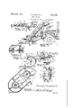
- Figure 3 is a view in side elevation ofthe implement of Figure 1 on'a reduced scale.
- Figure 5 is a transverse sectional view at line 5-,5 of Figure 1.
- Figure 6 is a. sectional view at line 6 6 of Figure 1 arts being broken away for convenience of 1llustration.
- Figure 7 is a top plan view of Figure 4 is a c a mount for one of the two caster Wheels of the implement, and
- Figure 8 is a side view of the wheel and its mount.-
- the implement is attached to an automotive vehicle, as a truck 1 having 55 the-usual wheels, one of the steering wheels being shown at 2, and the attaching frame of the implement includes a pair of side bars 3 and 4 of I-beams extending longitudinally at the front portion of the vehicle. These side bars are attached -to the frame or chassis of the vehicle by the use of U-bolts 5 and plates 5 in suitable manner in order that. the attaching Vframe may form a rigid and strong support for the carrier-frame 6 of the imple- ⁇ 6r ment.
- the carrier frame comprises a number of longitudinally extending bars that are joined by transverse braces or bars to form a rigid structure and the frame is provided With a platform, table, or deck 7 of .suitable 70 lengthn and width to, accommodate one or more men' as required.
- the frame and decl: are hingedor pivotally supported on the attaching frame by means of transversely extending pin 8, and at'the rear end of the car- 75 rier frame or tiltable frame *are carried a pair of downwardly extending rack arms 9.
- hese rack arms are for use in tilting the frame and they co-act with a pair of pinions t l0 on the transversely extending shaft 11, 80 mounted in suitable bearings on the attaching frame, and provided with-a crank handle 12 for turning the shaft and pinions.
- the rack arms are provided with a series of holes 13 and a selected one of these holes may be used 35 with complementary holesin the attachin frame for the insertion of a bolt or bolts 14- which retain the tiltable frame in adjusted position.
- the front of the implement may thus be raised or lowered with relation to the surface of the roadway to be cleared in order to insure most efficient service of the implement.
- the tiltable frame in front of the hingeor pivot 8 is provided with a pair of caster wheels 15 that are s aced apart and swiveled to afford a broad caring support for the tiltable frame and to facilitate the steering of the apparatus.
- the wheels are journaled in arms 16, and as best seen in Figures 7 and 8 w( the arms have a spindle 17 rigid therewith and projecting upwardly therefrom:
- a swivel head 18 1s provided for the s indle and a cotter pin 19 is used in the spin le to prevent displacement of these parts.
- Each swivel head is rigid with a U-shaped oke 20 and each yoke has an attaching racket 21. by means of which the. wheel mount may be bolted to suitable portions of the tiltable frame.
- the swivel head 18 1s fashioned with a pair of diametrically ai'- ranged trunnions 22 gournaled in bearings of the yoke and one o the truimions of each mount has a pinion 23 thereon.
- Each yoke supports a worm screw 24 journaled at 25 therein, and the worm screw of one wheel mount has a bevel gear wheel or pinion 26 that meshes with a complementary pinion 27 on the transversely extendmg shaft 28 that is journaled; in suitable bearings supported from the yokes of the mounts.
- evel pinion 29 on this cross shaft is engaged by a complementary pinion 30 on the section 31 of an operating bar which may be integral with the worm screw of one' of the mounts.
- the operating bar is made up of sections and universal joints as 32, and the sections 33 and 34 of the operating bar telescope as indicated in Fi re 1 to'permit adjustment of this sectiona bar. .I
- a second universal joint 35 is Aprovided and the bar may be turned'by means of a hand wheel 36 located in position accessible to the driver of the vehicle.
- hood 37 At the front of the tiltable carrier frame is supported a transversely extending hood 37 which is fashioned with a bottom or horizontal plow or scraper 38 having front V-teeth 39 for engagement with the snow, or ice as the vehicle moves forward.
- the upper, front portion of the hood hinged lid 40 having horizontal hinges 41 and a brace 42 hin ed at 43.
- the hinged lid may be raised, and in that position it is supported by the hinged brace, the lower free end of which is fastened by a keeper 44 on the rear of the main body of the hood.
- a air of guards 45 that ila-re outwardly and orwardly of the plow to guide the snow into the hood, and atthe left, forward side of the hoodv a second guard 46 is provided for pushing the snow laterally to the left as the vehicle advances.
- a rota screw 5 conveyer or excavator 47 with its s aft 48 and head with relation to the yoke, the
- naled in suitable bearin rotary screw is designe wardly extending eleft side of the implement and longitudinally of the vehicle.
- an endless belt or chain conveyer 50 having paddles or plates 51 to gather and elevate the snow from the hood tothe upper end of the housing.
- the endless chain conveyer or elevator passes around loose Pulleys or sprockets 52 on the conveyer sha t 48, and o ver complementary sprockets 53that are tight on the sprocket shaft 54 journaled in the upper end of the housing.
- the housing is rovided with a discharge spout 55 that is swiveled at 56 so that lthe snow ma be dischar d to either side of the vehic e or otherwise directed from the housing.
- the screw conveyer and the elevator are operated from a motor 57 of suitable ty to convey the snow through the hood to an u vhousing 49 arranged at t that is supported on the deck of the tiltab e A loose on the screw conveyer shaft.
- the screw conveyer shaft 48 is driven directly from the jack shaft or operating shaft 54 by means of an outside sprocket lwheel 60, chain 61 and the sprocket wheel 62 on the shaft 48, thus permitting the screw conveyer and the'elevator to be driven at relatively different speeds for conveying and elevating the snow.
- the lower end of the chain 61 and the sprocket wheel 62 are protected from the snow by the guard 46 which directs the snow away from t ese parts as the implement advances.
- the motor 57 may be an electric motor or an internal combustion engine, or other means may be used for supplying the power to the two conveyers.
Landscapes
- Engineering & Computer Science (AREA)
- Architecture (AREA)
- Civil Engineering (AREA)
- Structural Engineering (AREA)
- Handcart (AREA)
Description
March 29, 1932. G. w. BUNNELI.
SNOW REMOVER Filed March 25, 1929 2 Sheets-Sheet March 29, 1932. G. w. BUNNELI.
SNOW REMOVER Filed March 25, 1929v 2 sheets-sheet A Horne y APatented Mar. 29, 1932 lUNITED STATES PATENT @ENCE emanen mnomlmLL. 0F SANTA '1D-AH", I y
Application led Iaroh 25, 1929. Serial No. 349,335.
My present invention relates to improvements in snow removers of the roadwayexcavators type and mounted as a wheeled attachment at the front of an automotive vehicle, as a truck, for clearing the roads, streets,'and highways of snowwn carrying out my invention I utilize an attaching frame for su portin the implement at the front of the ve lele an this. frame has pivoted there- 0 in an adjustable and tiltable carrier-frame upon which are supported the excavators, conveyers and operating parts. The excavater is of the rotary screw type disposed transversely of the front of. the veh1cle and an upwardly inclined, longitudinal conveyor of the endless belt type is utilized for elevating and laterally delivering the snow at one or the other side of the road. Power, and operating means are carried upon the tiltable m table or platformY and manually operated ed P means are utilized for tilting the table to adjust the implement with relation to the surface of the roadway, and for adjusting the position of the wheeled supports of the implement in accordance wit the position of the implement.
The invention consists in certain novel combinations and arrangements of parts as will hereinafter be more fully set forth and claimed. In the accompanying drawings l have illustrated one example of the physical embodiment of my invention, wherein the parts. are combined and arranged according to one mode I have thus far devised for the practical application of the principles of my mvention. v
Figure 1 is a top plan view of the implement, partly broken away for convenience of illustration, and attached at the front of an automotive vehicle. Figure 2 is an enlarged detail view of the'manually operated means for tilting theV implement. Figure 3 is a view in side elevation ofthe implement of Figure 1 on'a reduced scale. transverse sectional detail view at line 4-4 of Figure 3. Figure 5 is a transverse sectional view at line 5-,5 of Figure 1. Figure 6 is a. sectional view at line 6 6 of Figure 1 arts being broken away for convenience of 1llustration. Figure 7 is a top plan view of Figure 4 is a c a mount for one of the two caster Wheels of the implement, and Figure 8 is a side view of the wheel and its mount.-
As before stated, the implement is attached to an automotive vehicle, as a truck 1 having 55 the-usual wheels, one of the steering wheels being shown at 2, and the attaching frame of the implement includes a pair of side bars 3 and 4 of I-beams extending longitudinally at the front portion of the vehicle. These side bars are attached -to the frame or chassis of the vehicle by the use of U-bolts 5 and plates 5 in suitable manner in order that. the attaching Vframe may form a rigid and strong support for the carrier-frame 6 of the imple- `6r ment. The carrier frame comprises a number of longitudinally extending bars that are joined by transverse braces or bars to form a rigid structure and the frame is provided With a platform, table, or deck 7 of .suitable 70 lengthn and width to, accommodate one or more men' as required. The frame and decl: are hingedor pivotally supported on the attaching frame by means of transversely extending pin 8, and at'the rear end of the car- 75 rier frame or tiltable frame *are carried a pair of downwardly extending rack arms 9.
hese rack arms are for use in tilting the frame and they co-act with a pair of pinions t l0 on the transversely extending shaft 11, 80 mounted in suitable bearings on the attaching frame, and provided with-a crank handle 12 for turning the shaft and pinions. The rack arms are provided with a series of holes 13 and a selected one of these holes may be used 35 with complementary holesin the attachin frame for the insertion of a bolt or bolts 14- which retain the tiltable frame in adjusted position. The front of the implement may thus be raised or lowered with relation to the surface of the roadway to be cleared in order to insure most efficient service of the implement. l
The tiltable frame in front of the hingeor pivot 8, is provided with a pair of caster wheels 15 that are s aced apart and swiveled to afford a broad caring support for the tiltable frame and to facilitate the steering of the apparatus. The wheels are journaled in arms 16, and as best seen in Figures 7 and 8 w( the arms have a spindle 17 rigid therewith and projecting upwardly therefrom: A swivel head 18 1s provided for the s indle and a cotter pin 19 is used in the spin le to prevent displacement of these parts.
Each swivel head is rigid with a U-shaped oke 20 and each yoke has an attaching racket 21. by means of which the. wheel mount may be bolted to suitable portions of the tiltable frame. The swivel head 18 1s fashioned with a pair of diametrically ai'- ranged trunnions 22 gournaled in bearings of the yoke and one o the truimions of each mount has a pinion 23 thereon. These pmions are turned, from the drivers seat of the vehicle, manually, for swinging the caster, its arms lattei` ,being rigid with the tiltable carrier frame, and the wheels are thus adjusted to com ensate for the changes in relation of the tilta le carrier frame to the road surface..
Each yoke supports a worm screw 24 journaled at 25 therein, and the worm screw of one wheel mount has a bevel gear wheel or pinion 26 that meshes with a complementary pinion 27 on the transversely extendmg shaft 28 that is journaled; in suitable bearings suported from the yokes of the mounts. evel pinion 29 on this cross shaft is engaged by a complementary pinion 30 on the section 31 of an operating bar which may be integral with the worm screw of one' of the mounts. The operating bar is made up of sections and universal joints as 32, and the sections 33 and 34 of the operating bar telescope as indicated in Fi re 1 to'permit adjustment of this sectiona bar. .I At the rear end of the sectional operating bar a second universal joint 35 is Aprovided and the bar may be turned'by means of a hand wheel 36 located in position accessible to the driver of the vehicle.
At the front of the tiltable carrier frame is supported a transversely extending hood 37 which is fashioned with a bottom or horizontal plow or scraper 38 having front V-teeth 39 for engagement with the snow, or ice as the vehicle moves forward. To accommodate the hood to various depths of snow, the upper, front portion of the hood hinged lid 40 having horizontal hinges 41 and a brace 42 hin ed at 43. As indicated by dotted lines in igure 5 the hinged lid may be raised, and in that position it is supported by the hinged brace, the lower free end of which is fastened by a keeper 44 on the rear of the main body of the hood.
At the opposite ends of the hood, and above the plow 38, are provided a air of guards 45 that ila-re outwardly and orwardly of the plow to guide the snow into the hood, and atthe left, forward side of the hoodv a second guard 46 is provided for pushing the snow laterally to the left as the vehicle advances.
Within the hood is carried a rota screw 5 conveyer or excavator 47 with its s aft 48 and head with relation to the yoke, the
is fashioned as a the vehicle and ourarranged transversely of s of the hood. The
naled in suitable bearin rotary screw is designe wardly extending eleft side of the implement and longitudinally of the vehicle. Within the housing is supported an endless belt or chain conveyer 50 having paddles or plates 51 to gather and elevate the snow from the hood tothe upper end of the housing.
-The endless chain conveyer or elevator passes around loose Pulleys or sprockets 52 on the conveyer sha t 48, and o ver complementary sprockets 53that are tight on the sprocket shaft 54 journaled in the upper end of the housing.- The housing is rovided with a discharge spout 55 that is swiveled at 56 so that lthe snow ma be dischar d to either side of the vehic e or otherwise directed from the housing. l
The screw conveyer and the elevator are operated from a motor 57 of suitable ty to convey the snow through the hood to an u vhousing 49 arranged at t that is supported on the deck of the tiltab e A loose on the screw conveyer shaft.v The screw conveyer shaft 48 is driven directly from the jack shaft or operating shaft 54 by means of an outside sprocket lwheel 60, chain 61 and the sprocket wheel 62 on the shaft 48, thus permitting the screw conveyer and the'elevator to be driven at relatively different speeds for conveying and elevating the snow. The lower end of the chain 61 and the sprocket wheel 62 are protected from the snow by the guard 46 which directs the snow away from t ese parts as the implement advances. The motor 57 may be an electric motor or an internal combustion engine, or other means may be used for supplying the power to the two conveyers.
Having thus fully described my invention what I claim as new and desire to secure by Letters Patent is v -1. The combination with an attaching frame of a hinged carrier frame, means for adjusting the carried frame and retaining means therefor, a hood mounted on the carrier frame and a plow projectin forward of the hood, said hood having a ifed lid and a brace for holding the 11d in adjusted osition, a rotary excavator supported within the'hood, an endless elevator, and means for operating said excavator and elevator.
2. The combination with r an attaching frame, of a tiltable carrier frame and means for retaining said frame in adjusted position, supporting wheels mounted under the carrier frame and means for` adjusting said wheels to compensate for relative adjustment of the carrier frame, a hood at the front of the carrier frame and 'a screw conveyer therein, an endless upright elevator co-operating with the screw conveyer, a motor mounted on the carrier frame, driving connections from the motor to the elevator, and driven connections from the elevator to the screw 5 conve er, said driven connections bein operate at different speed than the drlving connections.
3. The combination with an attac frame, of a tiltable carrier frame and a rac 10 arm on said frame, a, rack wheel on the attaching frame anda handle for said wheel, supporting wheels mounted under thecarrier frame and means for adjusting said wheels to compensate for relative movement 15 of the carrier frame a hood at the front of the carrier frame an a screw conve er therein, an endless upright elevator at t e side of the carrier frame and 'co-operating with the screw conveyer, 'a motor on the carrier frame 20 and driving connectionsthererom to the elevator, and driven connections from the elevator to the screw conveyer whereby the latter is driven at diierent speed from 'the former. 25 In testimony whereof I ailix my si nature.
GEORGE W. BUN ELL.
Priority Applications (1)
| Application Number | Priority Date | Filing Date | Title |
|---|---|---|---|
| US349835A US1851301A (en) | 1929-03-25 | 1929-03-25 | Snow remover |
Applications Claiming Priority (1)
| Application Number | Priority Date | Filing Date | Title |
|---|---|---|---|
| US349835A US1851301A (en) | 1929-03-25 | 1929-03-25 | Snow remover |
Publications (1)
| Publication Number | Publication Date |
|---|---|
| US1851301A true US1851301A (en) | 1932-03-29 |
Family
ID=23374151
Family Applications (1)
| Application Number | Title | Priority Date | Filing Date |
|---|---|---|---|
| US349835A Expired - Lifetime US1851301A (en) | 1929-03-25 | 1929-03-25 | Snow remover |
Country Status (1)
| Country | Link |
|---|---|
| US (1) | US1851301A (en) |
Cited By (7)
| Publication number | Priority date | Publication date | Assignee | Title |
|---|---|---|---|---|
| US2536763A (en) * | 1947-05-28 | 1951-01-02 | Knute E Nielsen | Automatic guide push elevator truck loader |
| US2642679A (en) * | 1949-05-16 | 1953-06-23 | Frank J Zamboni | Ice rink resurfacing machine |
| US2932101A (en) * | 1956-11-26 | 1960-04-12 | Ludowici Johann Wilhelm | Earth working machines |
| US3074188A (en) * | 1960-08-03 | 1963-01-22 | Robert E Etnyre | Snow clearing device |
| US3181258A (en) * | 1962-01-29 | 1965-05-04 | William W Duncan | Trench back filling and excavating machine |
| FR2086165A1 (en) * | 1970-04-17 | 1971-12-31 | Dunlop Co Ltd | |
| US4885852A (en) * | 1986-07-23 | 1989-12-12 | Gudmundsson Bjoern J | Snow removal apparatus and method |
-
1929
- 1929-03-25 US US349835A patent/US1851301A/en not_active Expired - Lifetime
Cited By (7)
| Publication number | Priority date | Publication date | Assignee | Title |
|---|---|---|---|---|
| US2536763A (en) * | 1947-05-28 | 1951-01-02 | Knute E Nielsen | Automatic guide push elevator truck loader |
| US2642679A (en) * | 1949-05-16 | 1953-06-23 | Frank J Zamboni | Ice rink resurfacing machine |
| US2932101A (en) * | 1956-11-26 | 1960-04-12 | Ludowici Johann Wilhelm | Earth working machines |
| US3074188A (en) * | 1960-08-03 | 1963-01-22 | Robert E Etnyre | Snow clearing device |
| US3181258A (en) * | 1962-01-29 | 1965-05-04 | William W Duncan | Trench back filling and excavating machine |
| FR2086165A1 (en) * | 1970-04-17 | 1971-12-31 | Dunlop Co Ltd | |
| US4885852A (en) * | 1986-07-23 | 1989-12-12 | Gudmundsson Bjoern J | Snow removal apparatus and method |
Similar Documents
| Publication | Publication Date | Title |
|---|---|---|
| US3456368A (en) | Snow removing and melting machine | |
| US1851301A (en) | Snow remover | |
| US2144312A (en) | Mounting for snow removing mechanism | |
| US1462527A (en) | Snow remover | |
| US2976936A (en) | Vehicles for cleaning beach sands | |
| US1957103A (en) | Snowplow | |
| US1508716A (en) | Automobile snowplow | |
| US2732573A (en) | hyland | |
| US1673457A (en) | Snow remover | |
| US4714149A (en) | Self propelled auger and separable vehicle therefor | |
| US1711488A (en) | Snowplow | |
| US2410012A (en) | Portable grain elevator | |
| US2601916A (en) | Portable grain conveyer | |
| US1407947A (en) | Snowplow | |
| US2090776A (en) | Road grader | |
| US2814889A (en) | Excavating machine | |
| US3281879A (en) | Street sweeper | |
| US2671281A (en) | Vehicular apparatus for removing snow and ice from streets and the like | |
| US1462901A (en) | Snowplow | |
| US2791043A (en) | Earth grading apparatus | |
| US1572026A (en) | Snowplow | |
| US1616835A (en) | Snow remover | |
| US1676823A (en) | Snow remover | |
| US1704475A (en) | Snowplow | |
| USRE20125E (en) | Snow plow attachment for |