US1851288A - Printer's registering device - Google Patents
Printer's registering device Download PDFInfo
- Publication number
- US1851288A US1851288A US378327A US37832729A US1851288A US 1851288 A US1851288 A US 1851288A US 378327 A US378327 A US 378327A US 37832729 A US37832729 A US 37832729A US 1851288 A US1851288 A US 1851288A
- Authority
- US
- United States
- Prior art keywords
- clamping
- groove
- plate
- screw
- registering device
- Prior art date
- Legal status (The legal status is an assumption and is not a legal conclusion. Google has not performed a legal analysis and makes no representation as to the accuracy of the status listed.)
- Expired - Lifetime
Links
Images
Classifications
-
- B—PERFORMING OPERATIONS; TRANSPORTING
- B41—PRINTING; LINING MACHINES; TYPEWRITERS; STAMPS
- B41F—PRINTING MACHINES OR PRESSES
- B41F27/00—Devices for attaching printing elements or formes to supports
- B41F27/04—Devices for attaching printing elements or formes to supports for attaching printing elements to flat type-beds
Definitions
- ATTORNEYE 1 retainedonagrooved'foundation'support by y Patented Mar. 29, 1932 .1
- a registering device which may be placed within the" groove of a foundation support and moved: to a position adj acent :the edge of a printingplate which it is desired'to hold, and then clamped inposition.
- Figure 2 is a fragmentarysectional view takenalong the lines 2+2 in Figure '1 f
- Figure 3 is a side elevation of a preferred Figure 4 is .
- I Figure 5 is a bottom plan view of the type ofdevices shown in the previously referred J Figureic-G is asectional viewj of the device PnmrING'MAcnInEn'Y oomranmbncmorn mrr, onidnoonronn'rlon OF OHIO I PRINTERSBEGISTERINGVZDEVICE 7 192a Serial No. 378,327.
- Figure 7 isa side elevation of a slightly modified type of registering device
- The'registering device in both modifica-' previously showntaken along the lines 656 T i tions has, preferably, a solid body .1 having I one, side provided with slanting surfaces 2at each end, on which are pivotally mounted the clamping plates 3 as indicated at 4.
- the other side 5 of'the body is provided with a substantially flat side with a fiang'e 6 at the lower end which,'with the top wall of the said side, makes an angle 1 corresponding to that of the inner wall of the; 4:
- an adj ustment screw 7. is provided which bears against the bottom wall of the groove, and during its adjusti'nent elevates the body until the clamping plates 3 and the flange and upper 'edgejot' the wall opposite bear against the wallsiof the groove.
- the ordinary foundation platewith which this type'of clamping device is adapted for use consists of a cylindrical orflat meme her 8,Ihaving;slots arranged transversely c therein.”
- the slots areof dovetailshape as .7 7 v i 8 Extendingthrough the body of the device,
- the clamping face can thus be used both to move the printing plate slightly, and to cause a more gripping engagement of the clamping face of the device against the edgeof the printing plate.
- FIG. 7 we have shown a modification which, however, is constructed on the same principle as the device illustrated in the other
- a body 20 figures. with clampingplates 3a, pivoted as indicated at 4a.
- An adjustment screw 7a clamps the body in the groove.
- the clamping jaw 130; has an adjustment screw 12a rotatably mounted therein.
- the screw has a flanged head 16 which seats against an annular bear- A ing surface 17.
- the screw has a squared hole 18 therein for'the reception of a key.
- a nut 19 having an inclined upper surface 20 which bears against the inclined trackwa s 10a.
- the operation of adjusting the b0 y and then moving the clamping face 14a relative to the bod is accomplished similar- 1 to the manner escribed for operating the device shown in the other figures.
- a printers' registering device having a body provided with adjustable means for retaining said body in a groove of a foundation support a plate clamping member, and means or moving said member relative to said bodjgicomprising an adjustment screw movable along inclined tracks in said body, said screw havin an enlarged head with beveled bearing sur aces.
- a printers registering device having a body provided with adjustable means for retaining said body in a groove of a foundation support, a plate clamping member, and means for moving said member relative to said body, comprising an adjustment screw movable along inclined tracks in said body, said screw having an enlarged head with beveled bearingsurfaces, and said inclined tracks being also I beveled.
- said device having a clamping jaw adjustable independently of said body clamping means, said adjustable clamping aw having an adjustment screw having an enlarged head with beveled bearing surfaces, and said body having inclined bearing tracks along which said beveled head is slidable during rotation of said screw.
- Aprinters registering device having a body provided with adjustable means for re taining said body in a groove of a foundation support, a plate clamping member slidable on the -upperpartof said body to clamp and unclamp a plate, said body having a downwardly facing surfaoeinclined upward in the direction in which said member slides to clamp the plate, and means movably engaging said inclined surface and said member to draw said member downwardly and also in clamping direction.
- a ,printers registering device having a body provided with adjustable means or retaining said body in agroove of a foundation sup ort, a plate clamping member slidable on t ie upper part of said body to clamp and unclamp a plate, and wedging means on said body and on said member, respectively, relatively movable to draw said member downwardly and also in clamping direction.
- a printers registering device having a body provided with adjustable means'for 're-' taining saidrbody in a groove ofa foundation support, a plate clamping member slidable on the upper part of said body to clamp and unclamp aplate, said body having an opening down through it, lower edges of said opening being inclined upward in the direction in which said member slides to clam the plate, and means extending through sai opening and movably engaging said inclined edges and said member to draw said member downwardly and also in clamping direction.
- a printcrs registering device' having a body provided withadjustable means for retaining said body in a groove of a founder tion'support, a plate clamping member slidable on the upper part of said bodyfto clamp and unclamp a plate, said body having an opening down through it, lower edges of said opening being inclined upward in the direction in which said member slides to clamp the plate, and a screw having a head up against said inclined edges, extending up through said opening and threaded into said clamping member and engageable through the top of said member for turning, whereby said member may bedrawndownwardly and also in clamping direction.
- a printers registering device having a body provided with adjustable means for retaining said body in a groove of a foundation support, a plate clamping memberfslidalble' on the upper part ofsaid body to clamp and unclamp a plate, said bodyhaving an opening down through it, lower edges of said openwhich said member slides to clamp the plate,
Landscapes
- Supply, Installation And Extraction Of Printed Sheets Or Plates (AREA)
- Clamps And Clips (AREA)
Description
March 29, 1932. E. F. NOELL ET AL 1,351,2g8
PRINTERS REGISTERING DEVICE Filed July 15, 1929 at; I r 3a.
9/ 6f 7. x 7 VBY IN VEN TORS.
ATTORNEYE 1 retainedonagrooved'foundation'support by y Patented Mar. 29, 1932 .1
NITED STAT S-1 ELMER a NOELLA'NlD EMILEQTH IEL," or omormva'rr, onrqnssrGnOns o THE adapted to be dropped into the grooves of a foundation plate, andbymanipulation hooked over the beveled edgeof a printing -plate to hold it in' position.
It is the object ,of our invention to provide a registering device which may be placed within the" groove of a foundation support and moved: to a position adj acent :the edge of a printingplate which it is desired'to hold, and then clamped inposition. In combinationwith the'body portion, thus adapted to seatwithin, and be clamped" within a groove,
it is our object to incorporate afclamping" hook mounting which, when actuated, will" rock the' clamping hook, so that itwill more tightly engage the edgelof a printing plate; Thus, it is our object-to provide a clamping body; carrying a clamping hook, whichis adjustable relative to thefbody.
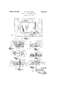
It is further. ourob'e'ct in the type of device noted, to 7 provide a structure [which will be simple, to make, whichfwill be inexpensive, considering the much Wider'range of ad ustability provided relativeto previously known devices, and which 'willbe eflicient mechanicall; i Y 1 l Theabove andother specific objects which willjbe hereinafter described, we accomplish by" that certain combination and arrangement of'p'artsof which we'have shown sev-' eral prefered, modifications. j J i Referring to the drawings:' Figure l fisa plan View ofa printing plate registering devices made in accordance with ourinvention,
Figure 2 is a fragmentarysectional view takenalong the lines 2+2 in Figure '1 f Figure 3 isa side elevation of a preferred Figure 4 is .a side elevation ofthe device shown in Figure 3 with the clamping plates elevatedi' 'J a I Figure 5 is a bottom plan view of the type ofdevices shown in the previously referred J Figureic-G is asectional viewj of the device PnmrING'MAcnInEn'Y oomranmbncmorn mrr, onidnoonronn'rlon OF OHIO I PRINTERSBEGISTERINGVZDEVICE 7 192a Serial No. 378,327.
in Figure 5. p a
' Figure 7 isa side elevation of a slightly modified type of registering device;
The'registering device in both modifica-' previously showntaken along the lines 656 T i tions has, preferably, a solid body .1 having I one, side provided with slanting surfaces 2at each end, on which are pivotally mounted the clamping plates 3 as indicated at 4. The
inclinationoftheouter surfacesof the clamp ing platesis such that #When inserted withina groove, the slanting outer surfaces of the plates will be parallel with the slant of the" wall of the groove. The other side 5 of'the body is provided with a substantially flat side with a fiang'e 6 at the lower end which,'with the top wall of the said side, makes an angle 1 corresponding to that of the inner wall of the; 4:
groove opposite that previously referred to, so that when the body is clamped within the groove there will be no tendency for thebody to ro'ck'laterally within the groove.
For clampingthe body withinthe groove of a foundation plate, an adj ustment screw 7. is providedwhich bears against the bottom wall of the groove, and during its adjusti'nent elevates the body until the clamping plates 3 and the flange and upper 'edgejot' the wall opposite bear against the wallsiof the groove. 'The ordinary foundation platewith which this type'of clamping device is adapted for use consists of a cylindrical orflat meme her 8,Ihaving;slots arranged transversely c therein." The slots areof dovetailshape as .7 7 v i 8 Extendingthrough the body of the device,
indicated in F igure 2;
we have-provided an opening 9, having bev ele'd'incline'dbearing surfaces 10 or slanting- I justment screw 12 will seat; The adjustment tracks,'against which the head 11 of an ad I screw is threaded in the clamping jaw mem- *ber 13. After the body of the device is seat ed within a dovetail groove,- whichmay be readily acoinplished by holding the device in the position shown in F igureA and by rock ing the'body slightly, manipulating it into position within thegroove, the plates 3 are pressed down into'the' position shown in Figure 3, and thescrew 7 is adjusted by means of i a key to lo'ck the body inthegroove.
head 11, 0 the screw. The clamping face can thus be used both to move the printing plate slightly, and to cause a more gripping engagement of the clamping face of the device against the edgeof the printing plate.
In the drawings, in Figure 1 a printing plate 15 is indicated held in position by four registering devices. j
a In Figure 7 we have shown a modification which, however, is constructed on the same principle as the device illustrated in the other Thus, we have provided a body 20 figures. with clampingplates 3a, pivoted as indicated at 4a. An adjustment screw 7a clamps the body in the groove. The clamping jaw 130; has an adjustment screw 12a rotatably mounted therein. The screw has a flanged head 16 which seats against an annular bear- A ing surface 17. The screw has a squared hole 18 therein for'the reception of a key. De-
tachably threaded on the end of the screw is a nut 19, having an inclined upper surface 20 which bears against the inclined trackwa s 10a. The operation of adjusting the b0 y and then moving the clamping face 14a relative to the bod is accomplished similar- 1 to the manner escribed for operating the device shown in the other figures.
While we have only shown two' modifications illustrating our invention it will be apparent that mechanical changes in the size, shape, and relation of parts will occur to others without departing from the principle involved.
7 Havingthus described our invention, what we claim as new and desire to secure by Letters Patent, is r 1. A printers' registering device having a body provided with adjustable means for retaining said body in a groove of a foundation support a plate clamping member, and means or moving said member relative to said bodjgicomprising an adjustment screw movable along inclined tracks in said body, said screw havin an enlarged head with beveled bearing sur aces.
2. A printers registering device having a body provided with adjustable means for retaining said body in a groove of a foundation support, a plate clamping member, and means for moving said member relative to said body, comprising an adjustment screw movable along inclined tracks in said body, said screw having an enlarged head with beveled bearingsurfaces, and said inclined tracks being also I beveled. I
3. A printers registeringdevicehaving a body provided with means for clamping same in a dovetail groove of a foundation support,
said device having a clamping jaw adjustable independently of said body clamping means, said adjustable clamping aw having an adjustment screw having an enlarged head with beveled bearing surfaces, and said body having inclined bearing tracks along which said beveled head is slidable during rotation of said screw.
4. Aprinters registering device having a body provided with adjustable means for re taining said body in a groove of a foundation support, a plate clamping member slidable on the -upperpartof said body to clamp and unclamp a plate, said body having a downwardly facing surfaoeinclined upward in the direction in which said member slides to clamp the plate, and means movably engaging said inclined surface and said member to draw said member downwardly and also in clamping direction.
5. A ,printers registering device having a body provided with adjustable means or retaining said body in agroove of a foundation sup ort, a plate clamping member slidable on t ie upper part of said body to clamp and unclamp a plate, and wedging means on said body and on said member, respectively, relatively movable to draw said member downwardly and also in clamping direction.
6. A printers registering device having a body provided with adjustable means'for 're-' taining saidrbody in a groove ofa foundation support, a plate clamping member slidable on the upper part of said body to clamp and unclamp aplate, said body having an opening down through it, lower edges of said opening being inclined upward in the direction in which said member slides to clam the plate, and means extending through sai opening and movably engaging said inclined edges and said member to draw said member downwardly and also in clamping direction.
7 A printcrs registering device'having a body provided withadjustable means for retaining said body in a groove of a founder tion'support, a plate clamping member slidable on the upper part of said bodyfto clamp and unclamp a plate, said body having an opening down through it, lower edges of said opening being inclined upward in the direction in which said member slides to clamp the plate, and a screw having a head up against said inclined edges, extending up through said opening and threaded into said clamping member and engageable through the top of said member for turning, whereby said member may bedrawndownwardly and also in clamping direction.
v 8. A printers registering device having a body provided with adjustable means for retaining said body in a groove of a foundation support, a plate clamping memberfslidalble' on the upper part ofsaid body to clamp and unclamp a plate, said bodyhaving an opening down through it, lower edges of said openwhich said member slides to clamp the plate,
a nut up against said inclined edges, and a screw extending down through said clamping member, rotatable in said memberiand engaging downwardly thereon and extending e down through said opening and threaded into i i said nut, said screw being enga eable in the upper part of said member or turning,
whereby said member may be drawn down-1- wardly and also in clamping direction. a
ELMER F. NOELL,
El/HLI E. THIEL.
Priority Applications (1)
| Application Number | Priority Date | Filing Date | Title |
|---|---|---|---|
| US378327A US1851288A (en) | 1929-07-15 | 1929-07-15 | Printer's registering device |
Applications Claiming Priority (1)
| Application Number | Priority Date | Filing Date | Title |
|---|---|---|---|
| US378327A US1851288A (en) | 1929-07-15 | 1929-07-15 | Printer's registering device |
Publications (1)
| Publication Number | Publication Date |
|---|---|
| US1851288A true US1851288A (en) | 1932-03-29 |
Family
ID=23492682
Family Applications (1)
| Application Number | Title | Priority Date | Filing Date |
|---|---|---|---|
| US378327A Expired - Lifetime US1851288A (en) | 1929-07-15 | 1929-07-15 | Printer's registering device |
Country Status (1)
| Country | Link |
|---|---|
| US (1) | US1851288A (en) |
-
1929
- 1929-07-15 US US378327A patent/US1851288A/en not_active Expired - Lifetime
Similar Documents
| Publication | Publication Date | Title |
|---|---|---|
| US3861664A (en) | Ski clamping device | |
| US1918439A (en) | Chuck | |
| US1851288A (en) | Printer's registering device | |
| US2627323A (en) | T-square and parallel straightedge combination | |
| US1818501A (en) | Universal vise | |
| US2447919A (en) | Adjustable support | |
| US2726060A (en) | Cam actuated attachment fitting | |
| US1870766A (en) | Camera mounting | |
| US2574834A (en) | Pipe wrench | |
| US1123960A (en) | Furniture-tread. | |
| US1947607A (en) | Clamping device | |
| US1445344A (en) | Tool | |
| US2043125A (en) | Clamping device | |
| US1397771A (en) | Adjustable work-carrying table for drilling and other machines | |
| US522651A (en) | Clamp | |
| US2838948A (en) | Lock mechanism for vise or clamp | |
| US1378209A (en) | Wrench | |
| US768929A (en) | Adjustable bracket. | |
| US2236135A (en) | Vise | |
| US1684038A (en) | Golf-ball marker | |
| US1299828A (en) | Vise. | |
| US372714A (en) | Planer-chuck | |
| US1268277A (en) | Lathe-turret. | |
| US809229A (en) | Printing-plate holder. | |
| US1188706A (en) | Automobile-chair. |