US1851275A - Portable electric light - Google Patents
Portable electric light Download PDFInfo
- Publication number
- US1851275A US1851275A US556628A US55662831A US1851275A US 1851275 A US1851275 A US 1851275A US 556628 A US556628 A US 556628A US 55662831 A US55662831 A US 55662831A US 1851275 A US1851275 A US 1851275A
- Authority
- US
- United States
- Prior art keywords
- casing
- cells
- members
- electric light
- lamp
- Prior art date
- Legal status (The legal status is an assumption and is not a legal conclusion. Google has not performed a legal analysis and makes no representation as to the accuracy of the status listed.)
- Expired - Lifetime
Links
- 239000011797 cavity material Substances 0.000 description 12
- 210000002105 tongue Anatomy 0.000 description 11
- 238000010276 construction Methods 0.000 description 4
- 230000008933 bodily movement Effects 0.000 description 2
- 238000009413 insulation Methods 0.000 description 2
- 239000004020 conductor Substances 0.000 description 1
- 208000002925 dental caries Diseases 0.000 description 1
- 230000005484 gravity Effects 0.000 description 1
- 230000013011 mating Effects 0.000 description 1
- 238000000926 separation method Methods 0.000 description 1
Images
Classifications
-
- F—MECHANICAL ENGINEERING; LIGHTING; HEATING; WEAPONS; BLASTING
- F21—LIGHTING
- F21L—LIGHTING DEVICES OR SYSTEMS THEREOF, BEING PORTABLE OR SPECIALLY ADAPTED FOR TRANSPORTATION
- F21L4/00—Electric lighting devices with self-contained electric batteries or cells
Definitions
- .casing membrs are QP iv v 1 16.511681] xh'e'fal stamp g m im*fmntme ib h s' t' iypliqqitimgpfiled; August 12,1931. "Serial wN o;556,628.
- the casing members are assembled together and engage with each other at their parting plane by entering the tongue features of the front member at the upper limit of the straight portion of the tongue,where it begins to curve over the arched top,in the open bottom end of the groove of the rear casing mem.- ber, and thrusting the rear member down to stopped position on the rearwardly protruding bottom element formed with the foot plate, E.
- a spring catch, 20 is provided at the lower edge of the web which forms the rear wall element of the rear casing member, and the foot plate has a hole, 21, with which the catch snaps into engagement at the limit of the down-thrust for interlocking the tongue-and-groove features; the spring catch being accessible at the under side of the hood plate is readily disengagejdfor withdrawing the rear casing member upwardly for access to the casing cavity for removing and replacing'cells and other attention as hereinafter described.
- the spring catch, 20 is formed as a lug of a plate, 22, which is riveted to the rear wall element of the rear casing member for furnlshmg pivotal engagement for the lower ends of a pair of loop handles, 25, 25,
- a bail, 50 pivotally attached to the front member at the upper end, that is, at a point substantially above the center of gravity of the total structure when occupied by cells.
- the bail attached to the front casing member it may be noted first,--as to the rear handle, that the means of engagement of the two casing members with each other by the vertically telescoping tongues and grooves respectively projecting and opening in the direction of the parting plane, enables the rear casing member held by the rear handles to carry the front casing member safely against liability of said front member to escape from the holding of the front member.
- the parabolic reflector intrudes from the forward side into the casing cavity, andthe boss,A accommodates a substantial portion of the actual dimension of the reflector,in that its inner end which, as mentioned, constitutes the socket for the lamp does not protrude beyond the parting plane of the casing members; and in view of its taper to the equal spaces between it and the opposite side of the casing cavity are sufficient to accommodate the cells respectively at opposite sides of the reflector; and the casing is transversely dimensioned relatively to the diameter of the standard dry. cells which are available for equipment of such a light device so that the cells while not pinched between the reflector and the casina' side walls are positioned safely against liability to escape from proper contact of their poles with the adjacent circuit elements.
- circuit elements include a receiving clip, 30, which is mounted insulatedly on the bottom element of the front casing member. as seen at 31, the insulation being indicated at 32.
- This clip is positioned in the foreand-aft vertical plane of the axis of the parabolic reflector for making contact with the center contact of the lamp as seen at d, and at its lower end it has a laterally extending arm, 33, which through its whole extent overhangs the insulation, 32. and which is stopped on the latter, which in turn rests flatly on the bottom element, E, of the front casing member; so that said bottom element member which has the bottom element having the tongue, and the other members having the grooves, said tongues and grooves'being continuous at the top element of the cavity-bounding flanges.
- a casing for a portable electric light havin cavities for accommodating lampenerglzing cells said casing comprising two casing members of which oneccontains a front wall and the other a rear wall of the casing,
- a portable electric light comprising a leasing having cavity for accommodating lamp-energizing cells, said casing having a front member and a rear member constructed for mutualengagement and for parting at a vertical plane intermediate the front and rear wallsof the casing cavity; a reflector carried b'y'the front member arranged for carrying a lamp condu'ctively mounted therein with the center contact of the lamp exposed interiorly of the casing, a conductive clip carried bythe front member for bearing on the inner side of the reflector to conduct the current to the outer contact of the lamp, a resilient conductive clip carried insulatedly by the front casing member and having a limb extended in position for lodgment thereon of an energizing cell at one side of said resiliently conductive strip, said front casing member having a bottom element arranged for lodgment thereon at the opposite side of of a second energizing cell, the rear casing member having mounted insulatedly onthe inner sidev of its rear wall, cooperating switch parts having resilient con tact terminals positioned
- a portable electric light device comlugs extending for encounter of the res supporting means being included in the circuit energized by the cells, a switch device comprising two switch terminals carried insulatedly by the casing and having each a resilient arm extending for conductive contact and resilient reaction upon the upper ends of. the cells respectively, and non-resilient stops carried insulatedly and fixedly by the casing extending for encounter by the upper ends of the cells respectively at the ient switch terminals to the thrust of the cells through said terminals.
- An electric light device comprising a casing arranged for carrying an electric lamp and energizing cells and circuit connections, clips carried by the casing for making the circuit connection throu h energizing cells and the lamp, and a switch device comprising co-operating parts having 'each a resilient contact terminal for circuit closing contact with the cells respectively, said switch members each having also a non-resilient lug, said ctive cells at the limit of a predetermined yielding of the resilient contact terminals to thrust'of the cells due to inertia of the cells upon abrupt bodily movement of the device longitudinally of the cells.
- An electric light device comprisin a casing, a pair of energizing cells mounte in the casing, cell supporting means carried by "the casing at one end of the cells, the cells opposite side of the cells, the casing having mounted in the forward side a reflector of electrically conductive material arranged for carrying a lamp, the lamp being conductively mounted in the reflector with its center contact exposed in the casing, and clips carried by the casing interiorly thereof suitably placed for completing the circuit through the cells which may be the switch members, the switch members having each a non-resilient arm extended for encounter of the respective cells at the limit of predetermined yielding of the resilient contact terminals due to inertia of the cells upon abrupt bodily movement of the device longitudinally of the cells.
- a portable electric light comprising a two membered casing having a cavity for accommodating lamp-energizing cells and circuit connections, said casing having its two casing members matedfor seating on' each other at a vertical parting plane, the front member comprising a lamp carrying reflecwa1l,rthe two casing members having their two mating edgesat their parting plane "co- J'their engagementtends'to defeat their'separation by stress "transversely of said'partoperatively formed” for tongue-and-groove vertical sliding engagement with the tongue projectinofficeithe groove opening in the direction of the parting "plane, whereby ing p1a'ne,-the rear memberhaving exterior handling means adapted for holding the lantern face-downward and directing it rigidly for projecting the beam at varying vertical angles, a .t I I I v CLARENCEP. DAVEY.
Landscapes
- Engineering & Computer Science (AREA)
- General Engineering & Computer Science (AREA)
- Tumbler Switches (AREA)
Description
March 29, 1932 c. P. DAVEY PORTABLE ELECTRIC LIGHT Filed Aug' 12. 1931 2 Sheets-Sheet l I e/We 72501 (ZifG/ZCGFJfi March 29, 1932, c. P. DAVEY PORTABLE ELECTRIC LIGHT 2 Sheets-Sheet 2 Filed Aug. 12, 1931 I Pfite nted Mar. 29," 1932;
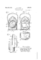
; EFFORTABLEELEGTRIC LIG T e ijhis 'nyentio'n is tqprovide I 12 n i l 'q mbl cntgnimbzg economical nignintiim'seihanflw p] (iffjslluc'hfl'clgvicsl The ins Bin h "e men simd f atu aslngn nxber', apz mteg from he' rolgi 51 mm. r;.is wingithj ifiz igi i ng cell s inp slit partly broken awayl v Figure].isi gul e ar iimelpside leyationof $12 f mlb w 'n mw b w l t 2 mm t tar nembe w thvvthe refiec torin posit dn n r is casing 'e mpln r i Wom A, and B hem uiafte'r referred to as the 1g mber, g and the *rear ,,;cas1ng .v i ehdxa artiaal par ng p ane ap- 'lma tel y' miclway between the f'mntand iis z-wg l vfithepas g i i s entirety, s a
V ,gah membgr.,contains."ajsubstaiitial part of j be taiaLgfifiys gnhyemQn cax ltp As 11113- t a edo- -the .qasmgi-memb rs.
mfp efn embbdyingi this These). .casing membrs are QP iv v 1 16.511681] xh'e'fal stamp g m im*fmntme ib h s' t' iypliqqitimgpfiled; August 12,1931. "Serial wN o;556,628.
fQfQfing what is, herinafter Qrefrrd. to as"? a light aperture, being; the. opening fitom which vthe light beam. is projected whenQthe lantern is in ,us. 'At thilightapertmie ,the re is l nolmtecl a suitiible refiegtor, G, p efezfaloly .50
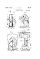
pzu'allolicj 01f il-ZlQliOIliHliljlQlY .pa itabolic said the wgircu ip and-grgove engagement by slilding reltive- [1v ptq 621d} pillar in .-t11e yertical'.directiorihf the ,pa-ittin rpl ane. the Rtongues, p'rot ryding ltwardly and the groovesloperiing inward 1y with yespectlto thecasing cav ity alidwwitlg respect my the, miter; ertical Qc l in-gminembers, said ion glies being? cbntinflous ver the upper. a rehed ends .of ihe front easing: membe! which is shown having the tongue {featm e ,andiheflgioove feature being similarly continlious ofiey the arched upper end (Sithe rear. casin g member. T11 59 upperzirizh ed end elementsiof fzhe casin members s1i,pp11i1 ,ent @achnfihex or formingthe top wall the calsiilg "cavity. The. Bottom, ele111ent-Qf, h (as mfg ,Cavity isv Carried; in entirety jbyfjghfe fmns c asin menfloer being iormed by a foot glafseg .ned permanently, aslby sdlder 'ing toihe lower endbf the front casing mam; bet}, 'A,.whigh' lattr to .afiordsub'stantial 111621118 for holding the foot pla te by some-r element, but having the flange which carries the groove continuous about the vertical sides and over the arched top.
Upon considering the construction thus far described, it may be understood that the casing members are assembled together and engage with each other at their parting plane by entering the tongue features of the front member at the upper limit of the straight portion of the tongue,where it begins to curve over the arched top,in the open bottom end of the groove of the rear casing mem.- ber, and thrusting the rear member down to stopped position on the rearwardly protruding bottom element formed with the foot plate, E.
For automatically engaging the rear casing member with the foot plate to hold the two members in inter-locked position of the tongue-and-groove features, a spring catch, 20, is provided at the lower edge of the web which forms the rear wall element of the rear casing member, and the foot plate has a hole, 21, with which the catch snaps into engagement at the limit of the down-thrust for interlocking the tongue-and-groove features; the spring catch being accessible at the under side of the hood plate is readily disengagejdfor withdrawing the rear casing member upwardly for access to the casing cavity for removing and replacing'cells and other attention as hereinafter described.
As shown,the spring catch, 20, is formed as a lug of a plate, 22, which is riveted to the rear wall element of the rear casing member for furnlshmg pivotal engagement for the lower ends of a pair of loop handles, 25, 25,
which have their upper ends pivotally engaged in suitable out-struck and apertured bosses, 26, 26, toward the upper end of the rear casing member. These handle members are adapted to fold over against the outer side of the casing member when not in use for handling the lantern, and are adapted to be swung into contact with each other, as seen in Figure 8, for being grasped together for handling the lantern somewhat. rigidly for directing the beam, especially when it is to be directed downwardly or upwardly, which cannot be done by handling it by the bail handle next described.
For the ordinary handling of the device after the. manner of a lantern to be carried pendant and required to be turned only for varying the horizontal direction of the beam, there 15 provided a bail, 50, pivotally attached to the front member at the upper end, that is, at a point substantially above the center of gravity of the total structure when occupied by cells.
Uponconsidering the construction particularly with respect to the relation of the two handling elements, viZ., a pair of loop handles a at the rear of the rear casing member, and
the bail attached to the front casing member,it may be noted first,--as to the rear handle, that the means of engagement of the two casing members with each other by the vertically telescoping tongues and grooves respectively projecting and opening in the direction of the parting plane, enables the rear casing member held by the rear handles to carry the front casing member safely against liability of said front member to escape from the holding of the front member. And with respect to the bail handle, it will be noted that the engagement of the two casing members with each other by the tongue and groove features of which the tongue is on the front casing member and is accordingly as to its extent across the top of the casing under the groove of the rear member at the part ex tending across the top, makes the front member to which the bail handle is attached to uphold the rear casing member against any liability of the latter to strip down along the side engagement, regardless of the rearwardlyextended bottom element of the front memher which it will be'recognized also and indepently of the relation of the ton 1e and groovesat the top, serves the same auction of enabling the front casing member to uphold the rear casing member. I i V The details of interior construction for 10- cating the cells in circuit with the lamp and switch members will now be described.
As mentioned above, the parabolic reflector intrudes from the forward side into the casing cavity, andthe boss,A accommodates a substantial portion of the actual dimension of the reflector,in that its inner end which, as mentioned, constitutes the socket for the lamp does not protrude beyond the parting plane of the casing members; and in view of its taper to the equal spaces between it and the opposite side of the casing cavity are sufficient to accommodate the cells respectively at opposite sides of the reflector; and the casing is transversely dimensioned relatively to the diameter of the standard dry. cells which are available for equipment of such a light device so that the cells while not pinched between the reflector and the casina' side walls are positioned safely against liability to escape from proper contact of their poles with the adjacent circuit elements.
These circuit elements include a receiving clip, 30, which is mounted insulatedly on the bottom element of the front casing member. as seen at 31, the insulation being indicated at 32. This clipis positioned in the foreand-aft vertical plane of the axis of the parabolic reflector for making contact with the center contact of the lamp as seen at d, and at its lower end it has a laterally extending arm, 33, which through its whole extent overhangs the insulation, 32. and which is stopped on the latter, which in turn rests flatly on the bottom element, E, of the front casing member; so that said bottom element member which has the bottom element having the tongue, and the other members having the grooves, said tongues and grooves'being continuous at the top element of the cavity-bounding flanges. V
6. In the construction defined in claim 4, the casing member having the bottom element being furnished also at'the upper part with a carrying bail. I
7. A casing for a portable electric light havin cavities for accommodating lampenerglzing cells, said casing comprising two casing members of which oneccontains a front wall and the other a rear wall of the casing,
, limit of predetermined yielding of the resiland of which each member contains a sub stantial part of the casing cavity with mar- Said cli ginal flanges bounding said cavity portions, the marginal flanges of the two members being furnished respectively with co-operating tongues and grooves for sliding engagement to inter-lock the casing members with-each other, said flanges and their respective tongue-and-groovc features being extended continuously with the opposite lateral, portions over the top of the respective casing members, the casing member whose flange has the tongue feature being furnished with a handle member for carrying the lamp pendant; t i
8. A portable electric light comprising a leasing having cavity for accommodating lamp-energizing cells, said casing having a front member and a rear member constructed for mutualengagement and for parting at a vertical plane intermediate the front and rear wallsof the casing cavity; a reflector carried b'y'the front member arranged for carrying a lamp condu'ctively mounted therein with the center contact of the lamp exposed interiorly of the casing, a conductive clip carried bythe front member for bearing on the inner side of the reflector to conduct the current to the outer contact of the lamp, a resilient conductive clip carried insulatedly by the front casing member and having a limb extended in position for lodgment thereon of an energizing cell at one side of said resiliently conductive strip, said front casing member having a bottom element arranged for lodgment thereon at the opposite side of of a second energizing cell, the rear casing member having mounted insulatedly onthe inner sidev of its rear wall, cooperating switch parts having resilient con tact terminals positioned for circuit closing contact with the upper end poles of the cells respectively, said switch members having each anon-resilient lug extending in position for encounterby the upper ends of the respective cells at the limit of a predetermined resilient yielding of the resilient switchterminalsto the thrust of the cells due to inversion of the light, or upward jolting of the cells.
9. A portable electric light device comlugs extending for encounter of the res supporting means being included in the circuit energized by the cells, a switch device comprising two switch terminals carried insulatedly by the casing and having each a resilient arm extending for conductive contact and resilient reaction upon the upper ends of. the cells respectively, and non-resilient stops carried insulatedly and fixedly by the casing extending for encounter by the upper ends of the cells respectively at the ient switch terminals to the thrust of the cells through said terminals.
10. An electric light device comprising a casing arranged for carrying an electric lamp and energizing cells and circuit connections, clips carried by the casing for making the circuit connection throu h energizing cells and the lamp, and a switch device comprising co-operating parts having 'each a resilient contact terminal for circuit closing contact with the cells respectively, said switch members each having also a non-resilient lug, said ctive cells at the limit of a predetermined yielding of the resilient contact terminals to thrust'of the cells due to inertia of the cells upon abrupt bodily movement of the device longitudinally of the cells. y 11. An electric light device comprisin a casing, a pair of energizing cells mounte in the casing, cell supporting means carried by "the casing at one end of the cells, the cells opposite side of the cells, the casing having mounted in the forward side a reflector of electrically conductive material arranged for carrying a lamp, the lamp being conductively mounted in the reflector with its center contact exposed in the casing, and clips carried by the casing interiorly thereof suitably placed for completing the circuit through the cells which may be the switch members, the switch members having each a non-resilient arm extended for encounter of the respective cells at the limit of predetermined yielding of the resilient contact terminals due to inertia of the cells upon abrupt bodily movement of the device longitudinally of the cells.
12. A portable electric light comprising a two membered casing having a cavity for accommodating lamp-energizing cells and circuit connections, said casing having its two casing members matedfor seating on' each other at a vertical parting plane, the front member comprising a lamp carrying reflecwa1l,rthe two casing members having their two mating edgesat their parting plane "co- J'their engagementtends'to defeat their'separation by stress "transversely of said'partoperatively formed" for tongue-and-groove vertical sliding engagement with the tongue projectingrandithe groove opening in the direction of the parting "plane, whereby ing p1a'ne,-the rear memberhaving exterior handling means adapted for holding the lantern face-downward and directing it rigidly for projecting the beam at varying vertical angles, a .t I I v CLARENCEP. DAVEY.
Priority Applications (1)
| Application Number | Priority Date | Filing Date | Title |
|---|---|---|---|
| US556628A US1851275A (en) | 1931-08-12 | 1931-08-12 | Portable electric light |
Applications Claiming Priority (1)
| Application Number | Priority Date | Filing Date | Title |
|---|---|---|---|
| US556628A US1851275A (en) | 1931-08-12 | 1931-08-12 | Portable electric light |
Publications (1)
| Publication Number | Publication Date |
|---|---|
| US1851275A true US1851275A (en) | 1932-03-29 |
Family
ID=24222155
Family Applications (1)
| Application Number | Title | Priority Date | Filing Date |
|---|---|---|---|
| US556628A Expired - Lifetime US1851275A (en) | 1931-08-12 | 1931-08-12 | Portable electric light |
Country Status (1)
| Country | Link |
|---|---|
| US (1) | US1851275A (en) |
-
1931
- 1931-08-12 US US556628A patent/US1851275A/en not_active Expired - Lifetime
Similar Documents
| Publication | Publication Date | Title |
|---|---|---|
| US3458794A (en) | Rechargeable device with rotatable plug | |
| EP0605133B1 (en) | Flashlight | |
| HK1000174B (en) | Flashlight | |
| US1851275A (en) | Portable electric light | |
| US2494375A (en) | Illuminated compact | |
| US2478129A (en) | Automatic emergency light | |
| US1925115A (en) | Battery lamp | |
| US1424578A (en) | Safety switch | |
| US2892274A (en) | Hand slide viewer | |
| US2481295A (en) | Combined key case and flashlight | |
| US2534945A (en) | Flashlight | |
| US2006251A (en) | Lighting unit for lanterns | |
| US1309140A (en) | Portable searchlight | |
| US1341471A (en) | Portable electric hand-lantern | |
| US2431607A (en) | Hinge construction | |
| US1126788A (en) | Electric switch. | |
| US1246042A (en) | Flash-light. | |
| US1481226A (en) | Storage battery or accumulator | |
| US1172354A (en) | Portable lamp. | |
| US1519044A (en) | Electric switch | |
| JPS6338527Y2 (en) | ||
| US1132750A (en) | Electric switch for portable electric lights. | |
| JPS5816382Y2 (en) | electric razor | |
| US1304856A (en) | Combined flash-light and mirror | |
| US2010089A (en) | Hand lantern |