US185126A - Improvement in car-couplings - Google Patents
Improvement in car-couplings Download PDFInfo
- Publication number
- US185126A US185126A US185126DA US185126A US 185126 A US185126 A US 185126A US 185126D A US185126D A US 185126DA US 185126 A US185126 A US 185126A
- Authority
- US
- United States
- Prior art keywords
- draw
- bar
- car
- link
- bumper
- Prior art date
- Legal status (The legal status is an assumption and is not a legal conclusion. Google has not performed a legal analysis and makes no representation as to the accuracy of the status listed.)
- Expired - Lifetime
Links
- 238000010168 coupling process Methods 0.000 title description 10
- 238000005859 coupling reaction Methods 0.000 title description 10
- 230000008878 coupling Effects 0.000 description 6
- 208000027418 Wounds and injury Diseases 0.000 description 1
- 230000006835 compression Effects 0.000 description 1
- 238000007906 compression Methods 0.000 description 1
- 238000010276 construction Methods 0.000 description 1
- 230000006378 damage Effects 0.000 description 1
- 230000005484 gravity Effects 0.000 description 1
- 208000014674 injury Diseases 0.000 description 1
- 238000000034 method Methods 0.000 description 1
- 230000000284 resting effect Effects 0.000 description 1
Images
Classifications
-
- B—PERFORMING OPERATIONS; TRANSPORTING
- B61—RAILWAYS
- B61G—COUPLINGS; DRAUGHT AND BUFFING APPLIANCES
- B61G9/00—Draw-gear
- B61G9/04—Draw-gear combined with buffing appliances
- B61G9/06—Draw-gear combined with buffing appliances with rubber springs
Definitions
- My invention relates to that class of carcouplings which automatically couple and connect railway-cars when the bumper-heads of such cars are brought together with a coup ling-link in one of the bumper-heads, and which may be uncoupled without compelling the operator to pass in between the cars.
- the invention consists in a novel construction of the draw-bar and its attachments, and in a novel arrangement of the same in relation to the bumper-head of a railway-car to which it is attached, whereby the coupling is automatically and certainly performed without distorting or buckling either the draw-bar or the coupling-link, or subjecting either said draw-bar or link toundue strain, and in such manner as to apply the draft wholly to the draw-bar to avoid the use of a coupling-pin, and permit the uncoupling to be performed from the top of a freight-car, or from the side' of a car when the operator stands upon the ground, thus avoiding the dangers and accidents attending the old method of coupling cars, and facilitating the making up and breaking up of trains.
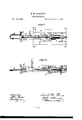
- Figure 1 is a top view, and Fig. 2 a vertical, central, and longitudinal section, of a bumper-head having my improved car-coupling attached thereto, and a portion of the floor'beams of a car to which the bumperhead and draw-bar are attached.
- A is the bumper-head, between the two parallel bars (6 of which is placedthe draw-bar b.
- the parallel bars a of the bumper-head extend for a considerable distance on each side of the draw-bar b, and are joined at their ends farthest from the link B by a cross-plate,
- a spring, g (preferably a coiled spring,)
- the sliding plate It On the inner end of the draw-bar b is cut a thread, upon which are fitted the nuts h and 'i and upon the said draw-bar are further arranged, as shown, the sliding plate It and the draft-plate [,the draftplate l having a central opening, m, Fig. 2, large enough to permit the free passage of the nut t.
- the sliding plate It has a hole in the center, through which the draw bar bpasses, but which does not permit the passage of the nut h.
- the plates 7 form guideways for the sliding plate 76 and a support for the draftplate, I, said slidin g plate and draft-plate being wider than the said plates 1', and the said sliding plate and draft-plate having recesses in their opposite ends, loosely fitting said plates 1.
- the drawbar b has a hook, it. formed upon its outer end, and near the said hook is attached to said draw-bar a chain, O,which, in use, is extended from said draw-bar to the top of car, or attached to a lever extending to the side of the car.
- the coupling and uncoupling are accomplished as follows:
- the weight of the drawbar is assisted by the action of the spring g, to depress the hooked end of the draw-bar, and to engage the hook it with the link B, when said link enters into the bumper-head in the usual manner, and the weight of the draw-bar, resting upon the inner part of said link, counter-balances and keeps the outer end of said link raised into the proper position to enter the bumper-head of the car to be coupled thereto, thus obviating the necessity of any special device for causing the link to keep the proper position for coupling.
- the outer end of the draw-bar b has an incline, 10, formed on its under side, which, through the pressure of the entering link, acts to raise the said outer or hooked end of said draw-bar, and permit the passage of the link under it, and when the link has entered by the point of the hook t the draw-bar drops by its own gravity and the action of the spring 9, and engages the said hook with the said link.
- the said spring g which is much weaker than the spring N, takes up the force of the impact of the link B, and prevents any injury to either the said link or draw-bar, a d furthermore, gives the requisite slack for starting long freight-trains.
- the ,strain is first transferred to the nut h, and thence, through the sliding plate 70, to the spring N; thence to the draft-plate l, and thence, through the plates 1', to the floor-beams s, rigidly attached to the car.
- the nut i then abutting against the cross-plate c of the bumper-head, causes said bumper-head to advance as much as the drawbar advances through the compression of the spring N, keeping the relation between said draw-bar and humperhead constantly the same during the interval between the coupling and uncoupling, whether the cars are in motion or otherwise.
- This arrangement prevents the hooked end of the draw-bar from ever coming in contact with the bumper-head, and removes all strain or draft from said bumper-head when the cars are in motion.
- the strain on the draw-bar is, moreover, always a pulling strain, tending to keep said draw-bar straight, and relieving it of any tendency to bend or buckle.
- adjustment of the draw'bar in relation to the draw-head may be made to adapt the coupling to coupling-links of different lengths, and to give more or less slack for freight or passenger trains.
- uncoupling the cars are run together in the usual manner, and the hooked end of the draw-bar is lifted enough to disengage it from the link B, when the cars may be separated.
Landscapes
- Engineering & Computer Science (AREA)
- Mechanical Engineering (AREA)
- Auxiliary Methods And Devices For Loading And Unloading (AREA)
Description
E. M. PA RRO TT:
CAR-COUPLING. No. 185,126. Pa'yented Dec.5, 1876.
HE GRAPHIC CU-N-Y Uivrrnn 'r EDWARD M. PARROTT, OF GREENWOOD IRON-WORKS, NEW YORK.
IMPROVEMENT IN CAR-COUPLINGS.
Specification forming part of Letters Patent No. 185,126, dated December 5, 1876; application filed October 11, 1876.
To all whom it may concern:
Be it known that I, EDWARD M. PARROTT, of Greenwood Iron-Works, in the county of Orange and State of New York, have invented an'lmprovement in Oar-Couplings; and I do hereby declare that thefollowin g is a full, clear, and exact description of the same, reference being had to the accompanying drawing, which forms a part of this specification.
My invention relates to that class of carcouplings which automatically couple and connect railway-cars when the bumper-heads of such cars are brought together with a coup ling-link in one of the bumper-heads, and which may be uncoupled without compelling the operator to pass in between the cars.
The invention consists in a novel construction of the draw-bar and its attachments, and in a novel arrangement of the same in relation to the bumper-head of a railway-car to which it is attached, whereby the coupling is automatically and certainly performed without distorting or buckling either the draw-bar or the coupling-link, or subjecting either said draw-bar or link toundue strain, and in such manner as to apply the draft wholly to the draw-bar to avoid the use of a coupling-pin, and permit the uncoupling to be performed from the top of a freight-car, or from the side' of a car when the operator stands upon the ground, thus avoiding the dangers and accidents attending the old method of coupling cars, and facilitating the making up and breaking up of trains.
Figure 1 is a top view, and Fig. 2 a vertical, central, and longitudinal section, of a bumper-head having my improved car-coupling attached thereto, and a portion of the floor'beams of a car to which the bumperhead and draw-bar are attached.
A is the bumper-head, between the two parallel bars (6 of which is placedthe draw-bar b. The parallel bars a of the bumper-head extend for a considerable distance on each side of the draw-bar b, and are joined at their ends farthest from the link B by a cross-plate,
0, through a central hole, (I, Fig. 2, in which the draw-bar b passes.
Between the said cross-plate c and a key, f, inserted through, or a shoulder formed on, the said draw-bar b is placed a spring, g, (preferably a coiled spring,)
surrounding said draw-bar. On the inner end of the draw-bar b is cut a thread, upon which are fitted the nuts h and 'i and upon the said draw-bar are further arranged, as shown, the sliding plate It and the draft-plate [,the draftplate l having a central opening, m, Fig. 2, large enough to permit the free passage of the nut t. The sliding plate It has a hole in the center, through which the draw bar bpasses, but which does not permit the passage of the nut h. Between the draft-plate Z and the sliding plate It is placed a strong spring, N, which normally presses the plates is and l asunder, and causes them to abut, respectively, against shoulders formed on the plates 1", attached to the floor-beams s of the car. The plates 7 form guideways for the sliding plate 76 and a support for the draftplate, I, said slidin g plate and draft-plate being wider than the said plates 1', and the said sliding plate and draft-plate having recesses in their opposite ends, loosely fitting said plates 1. The drawbar b has a hook, it. formed upon its outer end, and near the said hook is attached to said draw-bar a chain, O,which, in use, is extended from said draw-bar to the top of car, or attached to a lever extending to the side of the car.
The coupling and uncoupling are accomplished as follows: The weight of the drawbar is assisted by the action of the spring g, to depress the hooked end of the draw-bar, and to engage the hook it with the link B, when said link enters into the bumper-head in the usual manner, and the weight of the draw-bar, resting upon the inner part of said link, counter-balances and keeps the outer end of said link raised into the proper position to enter the bumper-head of the car to be coupled thereto, thus obviating the necessity of any special device for causing the link to keep the proper position for coupling. The outer end of the draw-bar b has an incline, 10, formed on its under side, which, through the pressure of the entering link, acts to raise the said outer or hooked end of said draw-bar, and permit the passage of the link under it, and when the link has entered by the point of the hook t the draw-bar drops by its own gravity and the action of the spring 9, and engages the said hook with the said link. Moreover,
the said spring g, which is much weaker than the spring N, takes up the force of the impact of the link B, and prevents any injury to either the said link or draw-bar, a d furthermore, gives the requisite slack for starting long freight-trains. When the draft is applied to the draw-bar b the ,strain is first transferred to the nut h, and thence, through the sliding plate 70, to the spring N; thence to the draft-plate l, and thence, through the plates 1', to the floor-beams s, rigidly attached to the car. The nut i, then abutting against the cross-plate c of the bumper-head, causes said bumper-head to advance as much as the drawbar advances through the compression of the spring N, keeping the relation between said draw-bar and humperhead constantly the same during the interval between the coupling and uncoupling, whether the cars are in motion or otherwise. This arrangement prevents the hooked end of the draw-bar from ever coming in contact with the bumper-head, and removes all strain or draft from said bumper-head when the cars are in motion. The strain on the draw-bar is, moreover, always a pulling strain, tending to keep said draw-bar straight, and relieving it of any tendency to bend or buckle.
By means of the nuts h and i, adjustment of the draw'bar in relation to the draw-head may be made to adapt the coupling to coupling-links of different lengths, and to give more or less slack for freight or passenger trains. In uncoupling, the cars are run together in the usual manner, and the hooked end of the draw-bar is lifted enough to disengage it from the link B, when the cars may be separated.
For lifting the hooked end of the draw-bar I directly employ the chain 0, which extends from said draw-bar to the top of the car; or, when standing on the ground, the operator may lift the draw-bar through a lever connected with said chain, for which chain a cord or rod may be substituted, if desired. For passenger-cars an elhowed lever may be applied, the longer arm standing vertically and adjusted to the hand-rail of the platform, the shorter arm being attached to the draw-bar by a few links of a chain.
I claim In combination with the bumper-head,- a hooked draw-bar, extending through the rear of the draw-head, the sliding plates k, guideplates 7, and draft-plate l, nuts h i, and springs g N, the springg acting on the draw-bar within the bumper-head, and the spring N acting 7 upon the sliding and draft plates, substantially as and for the purpose specified.
EDWARD M. PARROTT. Witnesses:
HENRY T. BROWN, BENJAMIN W, HOFFMAN.
Publications (1)
| Publication Number | Publication Date |
|---|---|
| US185126A true US185126A (en) | 1876-12-05 |
Family
ID=2254531
Family Applications (1)
| Application Number | Title | Priority Date | Filing Date |
|---|---|---|---|
| US185126D Expired - Lifetime US185126A (en) | Improvement in car-couplings |
Country Status (1)
| Country | Link |
|---|---|
| US (1) | US185126A (en) |
-
0
- US US185126D patent/US185126A/en not_active Expired - Lifetime
Similar Documents
| Publication | Publication Date | Title |
|---|---|---|
| US185126A (en) | Improvement in car-couplings | |
| US115627A (en) | Improvement in railway car-couplings | |
| US346551A (en) | Car-coupling | |
| US269456A (en) | pentz | |
| US160779A (en) | Improvement in car-couplings | |
| US279752A (en) | William h | |
| US273167A (en) | Car-coupling | |
| US316128A (en) | Car-coupling | |
| US272009A (en) | Car-coupling | |
| US320152A (en) | Car-coupling | |
| US259960A (en) | wilson | |
| US181971A (en) | Improvement in car-couplings | |
| US385027A (en) | Teeeitoet | |
| US279614A (en) | Benjamin f | |
| US453670A (en) | Car-coupling | |
| US250761A (en) | George w | |
| US643860A (en) | Automatic car-coupling. | |
| US443837A (en) | Car-coupling | |
| US163519A (en) | Improvement in car-couplings | |
| US197458A (en) | Improvement in car-couplings | |
| US273339A (en) | Car-coupling | |
| US545751A (en) | Car-coupling | |
| US325830A (en) | Winslow forbes | |
| US232348A (en) | Car-coupling | |
| US295588A (en) | Car-coupling |