US1851265A - Feeding mechanism for grinders - Google Patents
Feeding mechanism for grinders Download PDFInfo
- Publication number
- US1851265A US1851265A US328328A US32832828A US1851265A US 1851265 A US1851265 A US 1851265A US 328328 A US328328 A US 328328A US 32832828 A US32832828 A US 32832828A US 1851265 A US1851265 A US 1851265A
- Authority
- US
- United States
- Prior art keywords
- slide
- work
- roll
- support
- feed
- Prior art date
- Legal status (The legal status is an assumption and is not a legal conclusion. Google has not performed a legal analysis and makes no representation as to the accuracy of the status listed.)
- Expired - Lifetime
Links
- 230000001105 regulatory effect Effects 0.000 description 36
- 230000002093 peripheral effect Effects 0.000 description 8
- 230000000284 resting effect Effects 0.000 description 4
- 230000005484 gravity Effects 0.000 description 3
- 238000003780 insertion Methods 0.000 description 3
- 230000037431 insertion Effects 0.000 description 3
- 238000009877 rendering Methods 0.000 description 3
- 230000000903 blocking effect Effects 0.000 description 1
- 238000010276 construction Methods 0.000 description 1
- 230000001276 controlling effect Effects 0.000 description 1
Images

Classifications
-
- B—PERFORMING OPERATIONS; TRANSPORTING
- B24—GRINDING; POLISHING
- B24B—MACHINES, DEVICES, OR PROCESSES FOR GRINDING OR POLISHING; DRESSING OR CONDITIONING OF ABRADING SURFACES; FEEDING OF GRINDING, POLISHING, OR LAPPING AGENTS
- B24B5/00—Machines or devices designed for grinding surfaces of revolution on work, including those which also grind adjacent plane surfaces; Accessories therefor
- B24B5/35—Accessories
- B24B5/355—Feeding means
Definitions
- This invention relates to machines for centerless grinding, and more particularly to mechanism for automatically feeding work into grinding position between the'grinding and regulating wheels of such machines.
- An object of the invention is to provide simple and efficient means for feeding rolls or similar pieces to be ground, one at a time into grinding position within a centerless grinder, and more particularly a centerless grinder of the type shown in our application filed in the United States Patent Office, on November 26, 1928, Serial No. 321,807.
- a further object whereby rolls or the like are automatically fed in timed relation to the rotation of the regulating wheel of the grinding machine and which arrangement is such as to particularly adapt the mechanism to the feeding of rolls of truncated conical form.
- a further object is to provide means whereby the rolls are spaced and held and then released and fed, one at a time, and to provide certain other new and useful features in the construction and arrangement, all as hereinafter more fully set forth.
- Fig. 2 is a detail showing in end elevation, the mechanism shown in Fig. 1;
- Fig. 3 is a View showing in end elevation, the grinding wheel and regulating wheel of a centerless grinder to which the present invention is adapted to be applied;
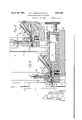
- Fig. 4 is a section substantially upon the line 44 of Fig. 1;
- the work feeding mechanism which is the v subject of this invention, is arranged and particularly adapted for use in feeding truncated conical rolls to the centerless grinder my application for and which grinder 1, and a regulating which is the subject of patent above referred to includes a grinding wheel wheel 2 arranged with their peripheries in' opposed and spaced apart relation to provide a grinding throat therebetween into 'which the work is introduced by the feeding mechanism hereinafter described.
- the machine also includes a work support 3 shown in Fig. 3 to support within the throat, the work while being ground, said support comprising a plate or plates projecting into the throat from one side of the wheels and provided with an end notch into which the rolls 4 are introduced endwise.
- the regulating wheel which is rotated in timed relation to the speed of the grindin 'wheel to give the desired differential perip heral speed between said wheels, and produce the desired grinding 5 to receive and guide the rolls and a portion of this groove is formed eccentric to the provide sufiicient space between grinding and regulating wheel peripheries during a portion of the rotation of the reguat the rolls may be inserted endwise into the holding notch in the support 3.
- the regulating wheel 2 with a peripheral notch 6 in which this groove terminates so that when said notch comes opposite the support 3, the roll being ground may drop from its support through said is also formed notch and be discharged from the machine.
- a roll 4 is therefore ground during each rotation of the regulating wheel'and to insert" a roll at a certain point of each rotation, a feed slide 10 is mounted for reciprocation in a suitable guideway 11 provided by a suitable supporting frame 12 mounted adjacent the end faces of the wheels 1 and 2 with the end of the slide'directed toward the open end of the seat or notch in the support 3 to receive the rolls.
- a feed pipe or chute 13 is supported by the frame 12 with the discharge endof said chute in position todischarge the rolls 4 into a groove let in the upper side of the forward end of this groove, and the bottom of this groove is curved transversely as shown in Fig. 2 to conform substantially to the cross-sectional curvature of the rolls.
- This groove is also formed with a step which provides a transverse shoulder 15 between the main part of said groove and an end portion 16, the bottom of the groove in'which end portion is inclined at an angle to the horizontal to correspond with the included angle of taper of the roll so that when a roll is resting within the groove of this end portion, its uppermost side will extend in a plane parallel with the plane of movement of the slide and the roll will lie upon an inclined sup port in a position to slide freely from the end of the slide when projected into the grind- 7 ing throat upon the support 3.
- the first roll or the one ahead of the slide is held against being pushed out until such time as the slide is projected forwardly in timed relation to the rotation of the regulating wheel, by a vertically movable foot 17 mounted in-a vertical guide 18 on the frame and normally, yieldingly held in its lowered position by means of a coiled spring 19 sleeved upon an adjustable stop bolt 20 secured to the upper end of the foot and passing freely through an end wall of the guide with adjusting nuts 21 on its outer end.
- the spring thus urges the foot downwardly to the limit of its movement as determined by the adjustment of the sto nuts 21.
- the forward end of the foot 17 15 formed with a rib 22 to engage the forward end of the roll 4 lying upon the bottom of the way 11 ahead of the end portion 16 of the slide, and a downward projection 23 on the heel portion of the foot engages the forward end of the roll which is resting upon the end portion'16 of the slide where said slide is in retracted position as shown in Fig. 5.
- the rear side of the projection 23 is beveled so that upon forward movement of the shde the said roll will be forced forwardly beneath said rojection by the engagement of its rear en with the shoulder 15.
- a cam rib 24 is provided on the end face of the regulating wheel 2 and a roller 25 mounted on a stud 26 projecting laterally from the slide 10 is adapted to roll upon this cam as the wheel turns and cause a reciprocation of the slide. forms the axle of the roll 25. also passing through openings in the forked end of a plunger 27 which is guided within a bore in the frame and serves to guide and support the roll.
- a stem 28 on the plunger 27 passes through a plate 29 covering the rear end of the bore in which the plunger reciprocates, and a coiled spring 30 is sleeved on this stem within the bore between the plunger and plate to exert a force yieldingly holding the roll in firm engagement with its cam 24, the slide 10 being thus positively moved in one direction by' the cam and yieldingly moved in the opposite direction by the spring 30 shown in dotted lines in Fig. 1.
- the stud 26 passes through and Should it be desirable to stop the feed without stopping the entire machine, the operation of the feed slide may be prevented by pulling outwardon the stem 28 of the plungor 27 against the action of the spring 30, by means of a hand wheel 31 on the outer end of the stem and then looking the stem and also retracted from its opening in the plate and then by turning the handle, the pin is moved out of alignment with said opening its end abutting the plate and holding the plunger 27 retracted against the action of sald spring 30 with the roller 25 out of con-v tact with its cam 24 and with the slide 10 in retracted position.
- a latch plate 33 is pivoted at 34 and has a laterally extending arm 35 adapted to pro ect across the path of the rolls and rest upon the rolls adjacerit the lower end of the chute when saidlatch is swung down- .Wardly onto the rolls at the end of the chute and hold the same in place against the action of the weight of the rolls in the chute.
- l l 1 In a centerless grinder, the combination of a grinding wheel, a regulating wheel in opposed peripheral spaced relation to said grinding wheel and forming a 1 grinding throat therebetween, said regulating wheel having a portion of its periphery formed to permit insertion of 7 work pieces into said throat, means forfeeding work pieces, one at a time, through said peripheral portion into. said throat, and means for operating said feeding means in timed relation. to the rotation of said regulating wheel to feed a work piece into said throat through said peripheral portion during each rotation of said wheel.
- a centerless grinder the combination of a grinding wheel, a regulating wheel in opposed peripheral spaced relation to said grinding wheel, said regulating wheel having a'portion of its periphery formed to permit insertion of work pieces into the space between said grinding and regulating wheels, a reciprocable feed member, and means for reciprocating said feed member in timed relation to the rotation of said regulating member to feed work pieces,-one at "a time, into said space between said wheels through said peripheral portion of said regulating wheel.
- a centerless grinder the combination of a grinding wheel, a, regulating wheel in opposed peripheral spaced relation to said grinding wheel, said regulating wheel having a portion of its periphery formed to permit'insertion of work pieces into the space 5 between said grinding and regulating wheels and a portion to permit the discharge of said pieces at the end of each rotation of said regulating wheel, a feed member for feeding a work piece into said space between said wheels at each rotation of said regulating wheel and in timed relation to the rotation of said wheel, and means for transmitting motion from said regulating wheel to operate said feed member.
- the combination slide, a chute fonfeeding work in the form of rolls to said slide said slide being formed with a stepped end portion forming a shoulder to engage the end of a roll, a vertically movable foot above the discharge end of said slide, said foot having downwardly extending portions to engage the ends of a roll therebeneath and means for reciprocating said slide.
- a grinder the combination with a grinding wheel and a regulating wheel, of a reciprocable feed slide, away for said slide, a chute for delivering work in the form of rolls to said way and slide, said slide havin a stepped end portion forming a shoul er and an'inclined seat, a foot above' said way, yieldable means for holding said foot moved towardsaid way, said foot having a rib to engage one end of a roll beneath said foot and having an" inclined portion at the other end of said roll to be engaged by a succeeding roll and lift said foot upon forward movement of said slide, means for reciprocating said slide in timed relation to with grinding means, of 'a reciprocable feedcenterless the rotation of saidregulating wheel, and means for locking said slide against reciprocation.
- a feeding mechanism for automatical- 1y inserting Work pieces into the throat of a centerless grinder the combination with a work rest blade within said throat, of a chute down which work pieces travel by gravity, a feeding slide at the terminus of said chute, a work support between said work rest blade and the feed slide for supporting the work piece to be next placed on the work rest blade, and means for actuating the feed slide to transfer the work piece on the support to the work rest, blade.
- a feeding mechanism for automatically inserting work pieces into the throat of a centerless grinder the combination with a work rest blade within said throat, of a chute down which work pieces travel by gravity, a feeding slide at the terminus of said chute, a work support between said work rest blade and the feed slide for supporting the work piece to be next placed on the work rest blade, means for actuating the feed slide to transfer the work piece on the support to the work rest blade, and a member overlying the work su port to prevent inadvertent discharge of t e work from the support, said member being rendered inoperative by a work piece on the feed slide during its forward movement.
- a feeding mechanism for automatically inserting work pieces into the throat of a rinder the combination with a work rest bide within said throat, of a chute down which work pieces travel by gravity, a feeding slide at the terminus of said chute, a work support between said work rest blade and the feed slide for supporting the work piece to be next placed on the work rest blade, means for actuating the feed slide to transfer the work piece on the support to the work rest blade, a member overlying the work support to prevent inadvertent dischar e of the work from the support, said mem er being rendered inoperative by a work piece on the feed slide during its forward movement, and means on the member for transferring a work piece on the feed slide to the work support.
- a device of the class described the combination with the throat of a -centerless grinder, of a work rest within said throat, a work support adjacent said work rest, a member overlying said support and normally preventing discharge of the work from the support, the member having a cam portion, a feed slide having a shoulder thereon and spaced from the free end thereof, said shoulder abutting the end of a work piece on the slide, and means for actuating the feed slide toward and from the grinding throat whereby the work piece and the slide engages the cam portion of the member for rendering feed slide having a a work same inoperative and the free end of the feed slide transfers the work piece from the work support to the work rest blade.
- a device-of the class described the combination with the throat of a centerless grinder, of a work rest within said throat, a work support adjacent said work rest, a member overyling said support and normally preventing discharge of the work from the support, the member having a cam portion, a shoulder thereon and spaced from the free end thereof, said shoulder abutting the end of a work piece on the slide, means for actuating the feed slide toward and from the grinding throat whereby the work piece and the slide engages the cam portion of the member for rendering same inoperative and the free end of the feed slide transfers the work piece from the work support to the work rest blade, a chute for delivering work pieces to the feed slide, and means for limiting the number of pieces delivered to the slide when same is moved in one direction.
- a member overlying said support and normally preventing discharge of the work from the support, the member having a cam portion, a feed slide having a shoulder thereon and spaced from the free end thereof, said shoulder abutting the end of a work piece on the slide, means for actuating the feed slide toward and from the grindmgthroat whereby the work piece and the slide engages the cam portion of the member for rendering same inoperative and the free end of the feed slide transfers the work piece from the work support to the work rest blade, a chute for delivering work pieces to the feed slide, means for limiting the number of pieces delivered to the slide when same is moved in one direction, a regulating wheel on one side-of the work rest blade, and means associated with the wheel for controlling the operation of the feed slide actuating means.
- a centerless grinder including a grinding wheel, a regulating wheel in opposed relation thereto with a space between the peripheries of said wheels forming a work receiving throat, a work support in said throat, said regulating wheel and the work support co-operatlng to maintain the position of the work against skewing and endwise movement, a feed slide for. feeding work into said throat upon said support, and means for operating said slide in timed relation to the rotation of said regulating wheel.
- a centerless grinder including a grinding wheel, a regulating wheel in opposed relation thereto with a space between the peripheries of said wheels forming a work receiving throat, a work support in said throat,
- said regulating wheel and the work support co-operating to maintain the position of the work against skewing and endwise movement, a feed slide for feeding work into said throat endwise of said support, a cam on said regulating wheel, and means engaging said cam for operating said slide.
Landscapes
- Engineering & Computer Science (AREA)
- Mechanical Engineering (AREA)
- Grinding Of Cylindrical And Plane Surfaces (AREA)
Description
March 29, 193 s. A. STRICKLAND ET AL FEEDING MECHANISM FOR GRINDERS Filed Dec: 26, 1928 2 Sheets-Sheet l INVENTORS 170;
a 0 05 Z/brme ATTORNEYS March 29, 19 s; A. STRICKLAND ET AL FEEDING MECHANISM FOR GRINDERS Filed Dec. 26, les 2 Sheets-Sheet 2 Patented Mar. 29, 1932 UNITED STATES PATEN T OFFICE SILAS A. STRIC'KLAND AND THOMAS ZIMMERMAN, OF DETROIT, MICHIGAN, ASSIGNORS,
BY MESNE ASSIGNMENTS, TO CIN NATI, OHIO, A CORPORATION OF OHIO .NNATI GRINDERS INCORPORATED, OF CINCIN- FEEDING MECHANISM FOR GRINDEBS Application filed December 26, 1928. Serial No. 328,328.
This invention relates to machines for centerless grinding, and more particularly to mechanism for automatically feeding work into grinding position between the'grinding and regulating wheels of such machines.
An object of the invention is to provide simple and efficient means for feeding rolls or similar pieces to be ground, one at a time into grinding position within a centerless grinder, and more particularly a centerless grinder of the type shown in our application filed in the United States Patent Office, on November 26, 1928, Serial No. 321,807. A further object whereby rolls or the like are automatically fed in timed relation to the rotation of the regulating wheel of the grinding machine and which arrangement is such as to particularly adapt the mechanism to the feeding of rolls of truncated conical form. A further object is to provide means whereby the rolls are spaced and held and then released and fed, one at a time, and to provide certain other new and useful features in the construction and arrangement, all as hereinafter more fully set forth.
With'the above and other ends in view, the invention consists in the matters hereinafter set forth and more particularly pointed out in the appended claims, reference being had to the accompanying drawings in which- Figure 1 is an enlarged sectional'detail of a portion of a centerless grinder, showing substantially in plan view,-feeding mechanism illustrative of an embodiment of the invention;
Fig. 2 is a detail showing in end elevation, the mechanism shown in Fig. 1;
Fig. 3 is a View showing in end elevation, the grinding wheel and regulating wheel of a centerless grinder to which the present invention is adapted to be applied;
Fig. 4 is a section substantially upon the line 44 of Fig. 1; and
is to provide an arrangementwheel axis to lating wheel, so th The work feeding mechanism which is the v subject of this invention, is arranged and particularly adapted for use in feeding truncated conical rolls to the centerless grinder my application for and which grinder 1, and a regulating which is the subject of patent above referred to includes a grinding wheel wheel 2 arranged with their peripheries in' opposed and spaced apart relation to provide a grinding throat therebetween into 'which the work is introduced by the feeding mechanism hereinafter described. The machine also includes a work support 3 shown in Fig. 3 to support within the throat, the work while being ground, said support comprising a plate or plates projecting into the throat from one side of the wheels and provided with an end notch into which the rolls 4 are introduced endwise. As shown in Fig. 3, the regulating wheel, which is rotated in timed relation to the speed of the grindin 'wheel to give the desired differential perip heral speed between said wheels, and produce the desired grinding 5 to receive and guide the rolls and a portion of this groove is formed eccentric to the provide sufiicient space between grinding and regulating wheel peripheries during a portion of the rotation of the reguat the rolls may be inserted endwise into the holding notch in the support 3. The regulating wheel 2 with a peripheral notch 6 in which this groove terminates so that when said notch comes opposite the support 3, the roll being ground may drop from its support through said is also formed notch and be discharged from the machine.
A roll 4 is therefore ground during each rotation of the regulating wheel'and to insert" a roll at a certain point of each rotation, a feed slide 10 is mounted for reciprocation in a suitable guideway 11 provided by a suitable supporting frame 12 mounted adjacent the end faces of the wheels 1 and 2 with the end of the slide'directed toward the open end of the seat or notch in the support 3 to receive the rolls. A feed pipe or chute 13 is supported by the frame 12 with the discharge endof said chute in position todischarge the rolls 4 into a groove let in the upper side of the forward end of this groove, and the bottom of this groove is curved transversely as shown in Fig. 2 to conform substantially to the cross-sectional curvature of the rolls. This groove is also formed with a step which provides a transverse shoulder 15 between the main part of said groove and an end portion 16, the bottom of the groove in'which end portion is inclined at an angle to the horizontal to correspond with the included angle of taper of the roll so that when a roll is resting within the groove of this end portion, its uppermost side will extend in a plane parallel with the plane of movement of the slide and the roll will lie upon an inclined sup port in a position to slide freely from the end of the slide when projected into the grind- 7 ing throat upon the support 3.
When the slide 10 is in retracted position I as shown in Fig. 5, the roll which was previously supported upon the end portion 16 of the slide as shown in Fig. 4, drops onto the bottom of the guideway 11 ahead of said end portion and the next roll in line falls onto said end portion ahead'of the;- shoulder 15, the third roll in line resting upon the slide and blocking the end of the chute by having its rear end beneath column of rolls in the chute, which column is thus supported by said third roll. The first roll or the one ahead of the slide, is held against being pushed out until such time as the slide is projected forwardly in timed relation to the rotation of the regulating wheel, by a vertically movable foot 17 mounted in-a vertical guide 18 on the frame and normally, yieldingly held in its lowered position by means of a coiled spring 19 sleeved upon an adjustable stop bolt 20 secured to the upper end of the foot and passing freely through an end wall of the guide with adjusting nuts 21 on its outer end. The spring thus urges the foot downwardly to the limit of its movement as determined by the adjustment of the sto nuts 21. The forward end of the foot 17 15 formed with a rib 22 to engage the forward end of the roll 4 lying upon the bottom of the way 11 ahead of the end portion 16 of the slide, and a downward projection 23 on the heel portion of the foot engages the forward end of the roll which is resting upon the end portion'16 of the slide where said slide is in retracted position as shown in Fig. 5. The rear side of the projection 23 is beveled so that upon forward movement of the shde the said roll will be forced forwardly beneath said rojection by the engagement of its rear en with the shoulder 15. This forcing of the roll into engagement with the inclined projection on the foot will lift the foot against the action of its spring and lift the rib 22 out of the path of the first roll, thus releasing said roll so that it may be pushed out by the engagement of the forward end of the slide with its rear end as the slide advances.
When the slide has reached the forward end of its movement as shown in Fig. 4, the
forward roll is in place within the grinding throat and the second roll resting on the end portion 16 of the slide has been caught between the rib 22 and projection 23 on the foot. The roll thus caught by the foot is therefore held in place while the slide is again being retracted and the next roll in line is separated therefrom and held back by engagement with theprojection 23. The rolls are therefore fed into the machine, one at a time and the succeeding rolls are held in position to be moved forwardly upon the next forward movement of the, slide, and positive and accurate feeding of the rolls is secured.
To positively feed the rolls in accurate timed relation to the rotation of the regulating wheel 2 so that when said wheel is in position to receive a roll between it and the grinding wheel, a roll will be fed in, a cam rib 24 is provided on the end face of the regulating wheel 2 and a roller 25 mounted on a stud 26 projecting laterally from the slide 10 is adapted to roll upon this cam as the wheel turns and cause a reciprocation of the slide. forms the axle of the roll 25. also passing through openings in the forked end of a plunger 27 which is guided within a bore in the frame and serves to guide and support the roll. A stem 28 on the plunger 27 passes through a plate 29 covering the rear end of the bore in which the plunger reciprocates, and a coiled spring 30 is sleeved on this stem within the bore between the plunger and plate to exert a force yieldingly holding the roll in firm engagement with its cam 24, the slide 10 being thus positively moved in one direction by' the cam and yieldingly moved in the opposite direction by the spring 30 shown in dotted lines in Fig. 1.
The stud 26 passes through and Should it be desirable to stop the feed without stopping the entire machine, the operation of the feed slide may be prevented by pulling outwardon the stem 28 of the plungor 27 against the action of the spring 30, by means of a hand wheel 31 on the outer end of the stem and then looking the stem and also retracted from its opening in the plate and then by turning the handle, the pin is moved out of alignment with said opening its end abutting the plate and holding the plunger 27 retracted against the action of sald spring 30 with the roller 25 out of con-v tact with its cam 24 and with the slide 10 in retracted position.
When the slide is held in inoperative position as described, there is nothing to prevent the rolls contained in the chute from workmg or sliding down, and perhaps piling up at the lower end of the chute. To obviate such contingency, a latch plate 33 is pivoted at 34 and has a laterally extending arm 35 adapted to pro ect across the path of the rolls and rest upon the rolls adjacerit the lower end of the chute when saidlatch is swung down- .Wardly onto the rolls at the end of the chute and hold the same in place against the action of the weight of the rolls in the chute.
While the present mechanism is particularly adapted for feeding truncated conical rolls, it is obvious-that changes may be made to adapt the same to feed rolls or other work pieces of different forms, and the employing of mechanical elements other than as shown is contemplated as falling within the scope of the appended claims.
' Having thus fully described our invention, what we claim is l l 1. In a centerless grinder, the combination of a grinding wheel, a regulating wheel in opposed peripheral spaced relation to said grinding wheel and forming a 1 grinding throat therebetween, said regulating wheel having a portion of its periphery formed to permit insertion of 7 work pieces into said throat, means forfeeding work pieces, one at a time, through said peripheral portion into. said throat, and means for operating said feeding means in timed relation. to the rotation of said regulating wheel to feed a work piece into said throat through said peripheral portion during each rotation of said wheel.
2. In a centerless grinder, the combination of a grinding wheel, a regulating wheel in opposed peripheral spaced relation to said grinding wheel, said regulating wheel having a'portion of its periphery formed to permit insertion of work pieces into the space between said grinding and regulating wheels, a reciprocable feed member, and means for reciprocating said feed member in timed relation to the rotation of said regulating member to feed work pieces,-one at "a time, into said space between said wheels through said peripheral portion of said regulating wheel.
3. In a centerless grinder, the combination of a grinding wheel, a, regulating wheel in opposed peripheral spaced relation to said grinding wheel, said regulating wheel having a portion of its periphery formed to permit'insertion of work pieces into the space 5 between said grinding and regulating wheels and a portion to permit the discharge of said pieces at the end of each rotation of said regulating wheel, a feed member for feeding a work piece into said space between said wheels at each rotation of said regulating wheel and in timed relation to the rotation of said wheel, and means for transmitting motion from said regulating wheel to operate said feed member.
4. A centerless grinder as characterized in claim 1 and further characterized by said feeding means including a reciprocable feed member, a chute for feeding work pieces to said feed member, a cam on the regulating wheel, and means engaged by said cam for reciprocating said feed member.
5. A centerless grinder as characterized in claim 1 and further characterized by said feeding means including a reciprocable'feed hold a work piece in the path of said slide and arranged to be moved by a succeeding work piece to release the piece held thereby when said succeeding piece is moved byforward movement of the slide, a cam on said regulating wheel, and means operated by said cam for reciprocating said slide in timed relation to the rotation of said regulating wheel. 7. In a centerless grinder, the combination slide, a chute fonfeeding work in the form of rolls to said slide, said slide being formed with a stepped end portion forming a shoulder to engage the end of a roll, a vertically movable foot above the discharge end of said slide, said foot having downwardly extending portions to engage the ends of a roll therebeneath and means for reciprocating said slide.
8. In a grinder, the combination with a grinding wheel and a regulating wheel, of a reciprocable feed slide, away for said slide, a chute for delivering work in the form of rolls to said way and slide, said slide havin a stepped end portion forming a shoul er and an'inclined seat, a foot above' said way, yieldable means for holding said foot moved towardsaid way, said foot having a rib to engage one end of a roll beneath said foot and having an" inclined portion at the other end of said roll to be engaged by a succeeding roll and lift said foot upon forward movement of said slide, means for reciprocating said slide in timed relation to with grinding means, of 'a reciprocable feedcenterless the rotation of saidregulating wheel, and means for locking said slide against reciprocation.
9. A feeding mechanism for automatical- 1y inserting Work pieces into the throat of a centerless grinder the combination with a work rest blade within said throat, of a chute down which work pieces travel by gravity, a feeding slide at the terminus of said chute, a work support between said work rest blade and the feed slide for supporting the work piece to be next placed on the work rest blade, and means for actuating the feed slide to transfer the work piece on the support to the work rest, blade.
10. A feeding mechanism for automatically inserting work pieces into the throat of a centerless grinder the combination with a work rest blade within said throat, of a chute down which work pieces travel by gravity, a feeding slide at the terminus of said chute, a work support between said work rest blade and the feed slide for supporting the work piece to be next placed on the work rest blade, means for actuating the feed slide to transfer the work piece on the support to the work rest blade, and a member overlying the work su port to prevent inadvertent discharge of t e work from the support, said member being rendered inoperative by a work piece on the feed slide during its forward movement.
11. A feeding mechanism for automatically inserting work pieces into the throat of a rinder the combination with a work rest bide within said throat, of a chute down which work pieces travel by gravity, a feeding slide at the terminus of said chute, a work support between said work rest blade and the feed slide for supporting the work piece to be next placed on the work rest blade, means for actuating the feed slide to transfer the work piece on the support to the work rest blade, a member overlying the work support to prevent inadvertent dischar e of the work from the support, said mem er being rendered inoperative by a work piece on the feed slide during its forward movement, and means on the member for transferring a work piece on the feed slide to the work support.
12. In a device of the class described the combination with the throat of a -centerless grinder, of a work rest within said throat, a work support adjacent said work rest, a member overlying said support and normally preventing discharge of the work from the support, the member having a cam portion, a feed slide having a shoulder thereon and spaced from the free end thereof, said shoulder abutting the end of a work piece on the slide, and means for actuating the feed slide toward and from the grinding throat whereby the work piece and the slide engages the cam portion of the member for rendering feed slide having a a work same inoperative and the free end of the feed slide transfers the work piece from the work support to the work rest blade.
13. In a device-of the class described the combination with the throat of a centerless grinder, of a work rest within said throat, a work support adjacent said work rest, a member overyling said support and normally preventing discharge of the work from the support, the member having a cam portion, a shoulder thereon and spaced from the free end thereof, said shoulder abutting the end of a work piece on the slide, means for actuating the feed slide toward and from the grinding throat whereby the work piece and the slide engages the cam portion of the member for rendering same inoperative and the free end of the feed slide transfers the work piece from the work support to the work rest blade, a chute for delivering work pieces to the feed slide, and means for limiting the number of pieces delivered to the slide when same is moved in one direction.
14. In a device of the class described the combination with thethroat of a center-less grinder,
support adjacent said work rest, a member overlying said support and normally preventing discharge of the work from the support, the member having a cam portion, a feed slide having a shoulder thereon and spaced from the free end thereof, said shoulder abutting the end of a work piece on the slide, means for actuating the feed slide toward and from the grindmgthroat whereby the work piece and the slide engages the cam portion of the member for rendering same inoperative and the free end of the feed slide transfers the work piece from the work support to the work rest blade, a chute for delivering work pieces to the feed slide, means for limiting the number of pieces delivered to the slide when same is moved in one direction, a regulating wheel on one side-of the work rest blade, and means associated with the wheel for controlling the operation of the feed slide actuating means.
15. A centerless grinder including a grinding wheel, a regulating wheel in opposed relation thereto with a space between the peripheries of said wheels forming a work receiving throat, a work support in said throat, said regulating wheel and the work support co-operatlng to maintain the position of the work against skewing and endwise movement, a feed slide for. feeding work into said throat upon said support, and means for operating said slide in timed relation to the rotation of said regulating wheel.
16. A centerless grinder including a grinding wheel, a regulating wheel in opposed relation thereto with a space between the peripheries of said wheels forming a work receiving throat, a work support in said throat,
of a work rest within said throat,
said regulating wheel and the work support co-operating to maintain the position of the work against skewing and endwise movement, a feed slide for feeding work into said throat endwise of said support, a cam on said regulating wheel, and means engaging said cam for operating said slide.
In testimony whereof We afiix our signatures.
SILAS A. STRICK'LAND. THOMAS ZIMMERMAN.
Priority Applications (1)
| Application Number | Priority Date | Filing Date | Title |
|---|---|---|---|
| US328328A US1851265A (en) | 1928-12-26 | 1928-12-26 | Feeding mechanism for grinders |
Applications Claiming Priority (1)
| Application Number | Priority Date | Filing Date | Title |
|---|---|---|---|
| US328328A US1851265A (en) | 1928-12-26 | 1928-12-26 | Feeding mechanism for grinders |
Publications (1)
| Publication Number | Publication Date |
|---|---|
| US1851265A true US1851265A (en) | 1932-03-29 |
Family
ID=23280526
Family Applications (1)
| Application Number | Title | Priority Date | Filing Date |
|---|---|---|---|
| US328328A Expired - Lifetime US1851265A (en) | 1928-12-26 | 1928-12-26 | Feeding mechanism for grinders |
Country Status (1)
| Country | Link |
|---|---|
| US (1) | US1851265A (en) |
Cited By (2)
| Publication number | Priority date | Publication date | Assignee | Title |
|---|---|---|---|---|
| DE1177032B (en) * | 1958-04-21 | 1964-08-27 | Cincinnati Milling Machine Co | Centerless grinding machine for tapered rollers |
| JP2020508883A (en) * | 2017-03-08 | 2020-03-26 | シェフラー テクノロジーズ アー・ゲー ウント コー. カー・ゲーSchaeffler Technologies AG & Co. KG | Loading device used for plunge grinder for centerless outer cylindrical grinding and method for centerless outer cylindrical grinding |
-
1928
- 1928-12-26 US US328328A patent/US1851265A/en not_active Expired - Lifetime
Cited By (3)
| Publication number | Priority date | Publication date | Assignee | Title |
|---|---|---|---|---|
| DE1177032B (en) * | 1958-04-21 | 1964-08-27 | Cincinnati Milling Machine Co | Centerless grinding machine for tapered rollers |
| JP2020508883A (en) * | 2017-03-08 | 2020-03-26 | シェフラー テクノロジーズ アー・ゲー ウント コー. カー・ゲーSchaeffler Technologies AG & Co. KG | Loading device used for plunge grinder for centerless outer cylindrical grinding and method for centerless outer cylindrical grinding |
| US11701745B2 (en) | 2017-03-08 | 2023-07-18 | Schaeffler Technologies AG & Co. KG | Loading device for a plunge cut grinding machine for centerless external cylindrical grinding and method for centerless external cylindrical grinding |
Similar Documents
| Publication | Publication Date | Title |
|---|---|---|
| US161811A (en) | Improvement in mechanisms for feeding heel-stiffeners or counter-blanks | |
| US1851265A (en) | Feeding mechanism for grinders | |
| US1897116A (en) | Nut blank sorter for tapping machines and the like | |
| US2052356A (en) | Assembly machine | |
| US2884747A (en) | Magnetic holder | |
| US2360991A (en) | Movable anvil riveting machine | |
| US2205468A (en) | Centerless grinding machine | |
| US1847466A (en) | Grinding machinery | |
| US2720734A (en) | Automatic infeed and ejecting devices for centerless grinders | |
| US2984423A (en) | Control device for roller mill | |
| US2156562A (en) | Centerless grinding machine | |
| US2222895A (en) | Blank feeding mechanism | |
| US2025714A (en) | Grinding machine | |
| US1814363A (en) | Grinding machinery | |
| US1582481A (en) | Grinding machine | |
| US1654213A (en) | Steady-rest mechanism for grinding machines | |
| US2579520A (en) | Centerless grinder | |
| US1931005A (en) | Automatic sorting machine | |
| US1757612A (en) | Centerless grinding machinery | |
| US1877515A (en) | Grinding machine | |
| US1791442A (en) | Grinding machine | |
| US1773937A (en) | Grinding machinery | |
| US1733094A (en) | Centerless grinder | |
| US2507334A (en) | Grinding of rollers | |
| US1193078A (en) | Island |