US1851260A - Automatic door closing device - Google Patents
Automatic door closing device Download PDFInfo
- Publication number
- US1851260A US1851260A US520216A US52021631A US1851260A US 1851260 A US1851260 A US 1851260A US 520216 A US520216 A US 520216A US 52021631 A US52021631 A US 52021631A US 1851260 A US1851260 A US 1851260A
- Authority
- US
- United States
- Prior art keywords
- arm
- casing
- door closing
- spring
- door
- Prior art date
- Legal status (The legal status is an assumption and is not a legal conclusion. Google has not performed a legal analysis and makes no representation as to the accuracy of the status listed.)
- Expired - Lifetime
Links
- 239000011435 rock Substances 0.000 description 2
- 238000010276 construction Methods 0.000 description 1
- OWFXIOWLTKNBAP-UHFFFAOYSA-N isoamyl nitrite Chemical compound CC(C)CCON=O OWFXIOWLTKNBAP-UHFFFAOYSA-N 0.000 description 1
- 239000000463 material Substances 0.000 description 1
Images
Classifications
-
- A—HUMAN NECESSITIES
- A62—LIFE-SAVING; FIRE-FIGHTING
- A62C—FIRE-FIGHTING
- A62C2/00—Fire prevention or containment
- A62C2/06—Physical fire-barriers
- A62C2/12—Hinged dampers
Definitions
- This ⁇ invention ⁇ relates to spring-actuated inertiaof thefdoorl atthe'startof ⁇ the closj.
- L v 1 is a door'vvhich may be of ordinary ⁇ iir'eproofrk yconstruction ,and is fprovidedfwith hinges2 supportedfon va doorrframe 3.
- a ⁇ projection 4 is also secured v.to and extends above the upper edgeV of the door;
- a .casing f 5. is secured to the door frame, this casingk 455 being rpreferably provided .With an integral bottom 6 anda removable top 6?. ⁇ Centrally of the casing is positioned: thevfspindle ⁇ 7.
- the spiral springg will thus/serve n, to move eitherthe arm 8 or ythe armv 11 depending on which vofthe two is' heldstation- ⁇ 'v ary.l y Furthermordthe, spring has aidirect o drivingwconnectionwiththe' triparm,-which 95 g f requires to be moved'rapidly, and has ageared 'i driving conneetionvvith the 'door loperating arm rwhich'.provides ample *power to over-k come the inertia of the door to ⁇ be moved-and set it inomotion.-
- the meansforl normally locking the door-fy voperating arm 8 in lan ⁇ inoperative, 'position Y ion 28 ⁇ meshes with gear Wheel 30 fast on the 80 i' comprises'fa pin 19 slidably inthe vcasing 5 l, and providedvvith a head 20fshaped as tanins verted cone. This headt is engageable ,bythe i inclinedportion-2l--ofthe trip army l1 so that Y. y
- the pin 19 is in onel piece and is formedwithv aportion Slot .reduced 1.00,
- the trip arm 11 is normally held in inoperative position by the wire 22 which may either be formed of readily fusible material or include a fusible link.
- the spring When the device is to he applied to a door, the spring is in an untensioned condition, making the device perfectly safe to handle. Vhen suitably secured in'place and connected up a Spanner may be applied to the ratchet wheel 25 to rotate the sleeve 9v to tension the y spring 18 as much as may be necessary, the
- What I claim as my invention is 1.
- a door closing device the combination of a'casing; a door closing arm and a trip arm concentrically 'journalled; a ro-l tatable member concentrically journalled with the said arms; a paWl-and-ratchet driving connection between or of the said arms and the said member; a sp -spring having one end connected with tha;I said member; and-a driving connection between the spring and the other arm.
- a door closing device the combination of a casing; a door closing arm and a trip arm rconcentrically journalled; a rotatable member concentrically journalled with the said arms; a pawl-and-ratchet driving con- I of a ⁇ casing; a door closing arm and a trip arm concentrically journalled; a spiral spring nection between the trip arm and the said member; a spiral spring having one end connected with the said member; and a dmving connectionfbetween the spring and the door closing arm.
- a door closing device the combination of a'casing; a doorclosing arm and a trip arm vconcentrically journalled; a rotatable member concentrically journalled with the said arms; a paWl-and-ratchet driving connection between one of the ysaid arms andthe said member; a spiral spring having one end connected with the said member; and a driving connection ybetween the spring and the other arm comprisinga train of 'speed reducing gearing.
- a door closing device the combination of a casing; a door closing army anda trip arm concentrically journalled; a rotatable member concentrically journalled with the said arms and having a driving connection with the trip arm; a second rotatable member concentrically journalled with said arms; a spiral sprin'ghaving its opposite Vend conoutside the casing; a rock arm on the sleevey inside the Casing; a sleeve on the spindle inside the casing; a' pinion on said sleeve; a spiral spring havingone end connected to the sleeveand'the other to the rock arm aforesaid; ⁇ a sleeve journalled on the spindle and in the lower end of the casing; a door closing arm fast on said sleeve outside the casing; a. gear Wheeljon said sleeve'within'the casing;
- a door closing device the combination of a casing; va door closing arm and a trip arm concentrically ⁇ ournailed; a rotatable member concentrically journalledwith said arms; a trip arm connected to the said member; a spiral spring having one end connected withsaid member; a driving connection'betweenthe other end of the spring and the door operating arm; ya oneiece pin -slidably mounted inthe ends of t e casing and positioned to engage the door closing arm and having abevelled lieadadapted to be engaged and lifted by the trip arm to disengage the door closing arm, the said pin having a portio'nfof reduced diameter intermediate of its ends; and a set screw threaded through the wall of the casing and engaging in said reduced portion to limit the endwise movements of the pin.
- a door closing device the combination positioned within the casing; a driving connectionA between the spring and each of said arms; a speed reducingr gear train included in one connection; and a pawl and ratchet included in one connection to permit of the tensioningof the spring after the device is assembled.
Landscapes
- Health & Medical Sciences (AREA)
- Public Health (AREA)
- Business, Economics & Management (AREA)
- Emergency Management (AREA)
- Closing And Opening Devices For Wings, And Checks For Wings (AREA)
Description
Marc-:h 29,l 1.932. w. R. MELMER 1,851,260
AUTOMATICA DOOR CLOSING DEVICE Filed March 5, 1931 Il l'lj 'nvemfor Patented Mai. y29,` `1932'y I 1 l '113851,260; if
WILLIAM n.' iunnnnmor TORONTO, QNTARI, CANADA;
AUTOMATIC noon cnosmefnnvrcn Application mea March 5,:
v This` invention `relates to spring-actuated inertiaof thefdoorl atthe'startof `the closj.
ing operation.; and r 4. A'construction which. is'readilyassem-r bled and installed-with the springin an `un-A tens'ioned? position; l
,I attain" my ob'ect 'by-V means of"v the con-` structionswhichy may fbe brieiiy Vdescribed as f follovvsrA'casing containing aspiral spring;
f is mounted on ythe door `trame and two arms are coneentrically `jnlrnalled thereon, one ak door-.operatingarm and the other a trip'arm adapted .to releasel `a :detentnormally hold# ing theidoor closingarm out of action. V.One
` off'said arms is connected With the springby: means. includingy a paWl if and y'ratchet 5 whereby the spring maybe tensioned after f U the devicev is`installed,vvhile the doorfoperating parmis driven bythe spring through a ytrain of speed' reducing gearing.
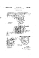
:Theinvention is hereinafter morefullydef` y 30, Y scribed and is :illustrated in theV accompanyring. drawings in which Y. e Y Fig. f1 is ak plan view of the device applied toadoor; M
3 Fig. 2 a verticalsectionjof the same;
remoti/'ed "from" the casing and Fig. i anseetional plan onx'the n in Fig52." L v 1 is a door'vvhich may be of ordinary `iir'eproofrk yconstruction ,and is fprovidedfwith hinges2 supportedfon va doorrframe 3. A` projection 4 is also secured v.to and extends above the upper edgeV of the door; A .casing f 5.is secured to the door frame, this casingk 455 being rpreferably provided .With an integral bottom 6 anda removable top 6?.` Centrally of the casing is positioned: thevfspindle` 7.
` J ournalled on they spindle Yand inthe bottom o 6'is a sleeve 2,3.to which isy secured the door.-
operating `arm l8.
0. 3 a side elevation of the movin'gpartsr 1931. serial No. 520,216.
The casing, it Will be noted, is so position-ed Y the axis on Which the doorfstvings.v Sleeved on the spindle isa sleeve 9, which is jour-f nalled in the top 6a ofthe casing. "Mounted 55 on the upperend ofthel spindleis the arm v ll,- Which serves "as atriparm.to release means normally holding'the door-operating arm 8in inoperative'position `as'hereinafter.-
y,*ATENfflv.V OFFICES 1 'that the spindle 7 is asY close as possiblefto described.` This arm is `provided fvvith `a x0y spring-actuated pawl 2 4:4V engagingV With A ratchet Wheel 25 suitablysecuredfon the ,up-,e per endjof thesleevegflflie sleeve23 may thus rotate relative Vtothe-arm in one direc-Y tion only. Formed oni .the sleeve-9 `and lo- 65e,
catedwithin they casing yis a `rock.arm 13 tol which is secured the pin 14. Y
Onqthe spindle 'i'fvvithin the casing'isgfposii tioned a sleeve 15. Y. Thissleeve isfree. to ro-` tate on the spindle. :Surrounding the sleeve, 7 0 `l5 is a spiral springlS, one endof which en-` e gages the pinV livvvhile theother isfhooked e into 'a' notch 'lOl iSv Otherwise-secured to the sleeve l5 (see'Fig 2),.. Y
Y Thisy sleevel has ap1n1on-26iformed there 75 Von Whichmeshesfwith Va gear Wheel127 tofV 'n ,I ,Whichis secured apinion 28, the gear Wheel and pinion beingkjournalledon a. pin 29 se-y cured to the bottom of thevcasin'g." VThe pin?y f sleeve 23. The spiral springgwill thus/serve n, to move eitherthe arm 8 or ythe armv 11 depending on which vofthe two is' heldstation-` 'v ary.l y Furthermordthe, spring has aidirect o drivingwconnectionwiththe' triparm,-which 95 g f requires to be moved'rapidly, and has ageared 'i driving conneetionvvith the 'door loperating arm rwhich'.provides ample *power to over-k come the inertia of the door to` be moved-and set it inomotion.-
The meansforl normally locking the door-fy voperating arm 8 in lan `inoperative, 'position Y ion 28 `meshes with gear Wheel 30 fast on the 80 i' comprises'fa pin 19 slidably inthe vcasing 5 l, and providedvvith a head 20fshaped as tanins verted cone. This headt is engageable ,bythe i inclinedportion-2l--ofthe trip army l1 so that Y. y
itgmaybe lifted and its=lovver1enddisengaged i4 fromV :the arm 8y to `'allo'vtf the 4latter to 'swing to operatethe door. The pin 19 is in onel piece and is formedwithv aportion Slot .reduced 1.00,
las
diameter and a set screw 32 threaded through the Wall of the casing projects into the recess so formed to'limit the movements of the pin in either direction. The trip arm 11 is normally held in inoperative position by the wire 22 which may either be formed of readily fusible material or include a fusible link.
When the device is to he applied to a door, the spring is in an untensioned condition, making the device perfectly safe to handle. Vhen suitably secured in'place and connected up a Spanner may be applied to the ratchet wheel 25 to rotate the sleeve 9v to tension the y spring 18 as much as may be necessary, the
spring`18 is exercised through the arm 8- to close the door.
What I claim as my invention is 1. In a door closing device, the combination of a'casing; a door closing arm and a trip arm concentrically 'journalled; a ro-l tatable member concentrically journalled with the said arms; a paWl-and-ratchet driving connection between or of the said arms and the said member; a sp -spring having one end connected with tha;I said member; and-a driving connection between the spring and the other arm. y
2. f In a door closing device, the combination of a casing; a door closing arm and a trip arm rconcentrically journalled; a rotatable member concentrically journalled with the said arms; a pawl-and-ratchet driving con- I of a` casing; a door closing arm and a trip arm concentrically journalled; a spiral spring nection between the trip arm and the said member; a spiral spring having one end connected with the said member; and a dmving connectionfbetween the spring and the door closing arm. l
3. In a door closing device, the combination of a'casing; a doorclosing arm and a trip arm vconcentrically journalled; a rotatable member concentrically journalled with the said arms; a paWl-and-ratchet driving connection between one of the ysaid arms andthe said member; a spiral spring having one end connected with the said member; and a driving connection ybetween the spring and the other arm comprisinga train of 'speed reducing gearing. Y
- 4. `In a door closing device, the combination of a casing; a door closing army anda trip arm concentrically journalled; a rotatable member concentrically journalled with the said arms and having a driving connection with the trip arm; a second rotatable member concentrically journalled with said arms; a spiral sprin'ghaving its opposite Vend conoutside the casing; a rock arm on the sleevey inside the Casing; a sleeve on the spindle inside the casing; a' pinion on said sleeve; a spiral spring havingone end connected to the sleeveand'the other to the rock arm aforesaid; `a sleeve journalled on the spindle and in the lower end of the casing; a door closing arm fast on said sleeve outside the casing; a. gear Wheeljon said sleeve'within'the casing;
and a connectedA pinion and gear wheel co,
axially journalled within the casing, the former meshing with the gear wheel and the latter with the pinion aforesaid.
6. In a door closing device, the combination of a casing; va door closing arm and a trip arm concentrically `ournailed; a rotatable member concentrically journalledwith said arms; a trip arm connected to the said member; a spiral spring having one end connected withsaid member; a driving connection'betweenthe other end of the spring and the door operating arm; ya oneiece pin -slidably mounted inthe ends of t e casing and positioned to engage the door closing arm and having abevelled lieadadapted to be engaged and lifted by the trip arm to disengage the door closing arm, the said pin having a portio'nfof reduced diameter intermediate of its ends; and a set screw threaded through the wall of the casing and engaging in said reduced portion to limit the endwise movements of the pin. f Y
7. In a door closing device, the combination positioned within the casing; a driving connectionA between the spring and each of said arms; a speed reducingr gear train included in one connection; and a pawl and ratchet included in one connection to permit of the tensioningof the spring after the device is assembled.
Signed at Toronto this 10th day of February; 1931.
WILLIAM R.` MELMER.
yist
Priority Applications (1)
| Application Number | Priority Date | Filing Date | Title |
|---|---|---|---|
| US520216A US1851260A (en) | 1931-03-05 | 1931-03-05 | Automatic door closing device |
Applications Claiming Priority (1)
| Application Number | Priority Date | Filing Date | Title |
|---|---|---|---|
| US520216A US1851260A (en) | 1931-03-05 | 1931-03-05 | Automatic door closing device |
Publications (1)
| Publication Number | Publication Date |
|---|---|
| US1851260A true US1851260A (en) | 1932-03-29 |
Family
ID=24071650
Family Applications (1)
| Application Number | Title | Priority Date | Filing Date |
|---|---|---|---|
| US520216A Expired - Lifetime US1851260A (en) | 1931-03-05 | 1931-03-05 | Automatic door closing device |
Country Status (1)
| Country | Link |
|---|---|
| US (1) | US1851260A (en) |
Cited By (1)
| Publication number | Priority date | Publication date | Assignee | Title |
|---|---|---|---|---|
| US2637548A (en) * | 1951-07-11 | 1953-05-05 | Gzupkaytii Matt | Window operator |
-
1931
- 1931-03-05 US US520216A patent/US1851260A/en not_active Expired - Lifetime
Cited By (1)
| Publication number | Priority date | Publication date | Assignee | Title |
|---|---|---|---|---|
| US2637548A (en) * | 1951-07-11 | 1953-05-05 | Gzupkaytii Matt | Window operator |
Similar Documents
| Publication | Publication Date | Title |
|---|---|---|
| US948239A (en) | Fireproof-shutter mechanism. | |
| US1851260A (en) | Automatic door closing device | |
| US3866656A (en) | Folding blade fire damper | |
| US1804709A (en) | Thermomotive device | |
| US1853150A (en) | Spring controlled roller for roller blinds | |
| US1535502A (en) | Mechanical spinning top | |
| US1507525A (en) | Door catch | |
| US1401952A (en) | Spinning top | |
| GB1230391A (en) | ||
| US1580286A (en) | Station indicator | |
| US935545A (en) | Clutch for transom-rods. | |
| US1415874A (en) | Automatic alarm | |
| US1161618A (en) | Self-contained time-controlled operating mechanism. | |
| US3805449A (en) | Remote-controlled device for rapidly opening a skylight | |
| US2089882A (en) | Antiflood oil burner attachment | |
| US2751053A (en) | Holder | |
| US1608402A (en) | Automatic door-closing device | |
| DE463692C (en) | Automatic fire protection device | |
| US1377628A (en) | Car-brake-controlling means | |
| US1530652A (en) | Automatic fire shutter | |
| US1661652A (en) | Lever sash regulator | |
| US1617268A (en) | Railway signaling device | |
| GB322549A (en) | Improvements in door closing springs | |
| US1720793A (en) | Heat-operated alarm | |
| SU19917A1 (en) | Film projector fire extinguisher |