US1851259A - Valve - Google Patents
Valve Download PDFInfo
- Publication number
- US1851259A US1851259A US24399227A US1851259A US 1851259 A US1851259 A US 1851259A US 24399227 A US24399227 A US 24399227A US 1851259 A US1851259 A US 1851259A
- Authority
- US
- United States
- Prior art keywords
- valve
- lubricant
- seat
- plug
- plate
- Prior art date
- Legal status (The legal status is an assumption and is not a legal conclusion. Google has not performed a legal analysis and makes no representation as to the accuracy of the status listed.)
- Expired - Lifetime
Links
- 239000000314 lubricant Substances 0.000 description 83
- 230000001050 lubricating effect Effects 0.000 description 10
- 230000006835 compression Effects 0.000 description 9
- 238000007906 compression Methods 0.000 description 9
- 239000012530 fluid Substances 0.000 description 7
- 238000012856 packing Methods 0.000 description 5
- 238000010276 construction Methods 0.000 description 4
- 210000004907 gland Anatomy 0.000 description 3
- 238000004140 cleaning Methods 0.000 description 2
- 238000006073 displacement reaction Methods 0.000 description 2
- 239000004519 grease Substances 0.000 description 2
- 241001304230 Progne cryptoleuca Species 0.000 description 1
- 238000003754 machining Methods 0.000 description 1
- 239000000463 material Substances 0.000 description 1
- 229920000136 polysorbate Polymers 0.000 description 1
- 239000012858 resilient material Substances 0.000 description 1
Images

Classifications
-
- F—MECHANICAL ENGINEERING; LIGHTING; HEATING; WEAPONS; BLASTING
- F16—ENGINEERING ELEMENTS AND UNITS; GENERAL MEASURES FOR PRODUCING AND MAINTAINING EFFECTIVE FUNCTIONING OF MACHINES OR INSTALLATIONS; THERMAL INSULATION IN GENERAL
- F16K—VALVES; TAPS; COCKS; ACTUATING-FLOATS; DEVICES FOR VENTING OR AERATING
- F16K5/00—Plug valves; Taps or cocks comprising only cut-off apparatus having at least one of the sealing faces shaped as a more or less complete surface of a solid of revolution, the opening and closing movement being predominantly rotary
- F16K5/08—Details
- F16K5/22—Features relating to lubrication
- F16K5/222—Features relating to lubrication for plugs with conical surfaces
-
- Y—GENERAL TAGGING OF NEW TECHNOLOGICAL DEVELOPMENTS; GENERAL TAGGING OF CROSS-SECTIONAL TECHNOLOGIES SPANNING OVER SEVERAL SECTIONS OF THE IPC; TECHNICAL SUBJECTS COVERED BY FORMER USPC CROSS-REFERENCE ART COLLECTIONS [XRACs] AND DIGESTS
- Y10—TECHNICAL SUBJECTS COVERED BY FORMER USPC
- Y10T—TECHNICAL SUBJECTS COVERED BY FORMER US CLASSIFICATION
- Y10T137/00—Fluid handling
- Y10T137/4238—With cleaner, lubrication added to fluid or liquid sealing at valve interface
- Y10T137/4358—Liquid supplied at valve interface
- Y10T137/4393—Screw feed
- Y10T137/44—With check valve
- Y10T137/4414—Jacking
Definitions
- the present invention relates in general to valves and more particularly to valves having a lubricant introduced between the valve member and the valve seat, and has special reference to the provision of an improved type of plug valve of the character referred to, wherein lubricant is employed to prevent sticking of the valve upon its seat and to prevent leakage of fluid therebetween.
- an improved valve structure and lubricating means therefor incorporating therein auxiliary means for lifting the valve from its seatby the action of the lubricant under pressure; the provision of an improved means for maintaining a supply of the lubricant in eiective position; the provision in a lubricated valve of an improved construction of lubricant chamber whereby to increase the capacity of the chamber and thereby increase the intervals to which it is necessary to replenish the lubricant; the provision in an improved valve structure of an improved pressure sensitive element for displacing the valve away from its seat to permit the introduction of a lubricant to the seating' surface of the Valve and casing; the provision of an improved means for permitting of the simpliied adjustment of the valve structure and lubricating means; the provision of a lubricated plug valve structure incorporating therein an improved arrangement whereby cleaning and repairing of the parts is facilitated; and the provision of a valve of the character referred to wherein the means for holding the valve normally on its seat is eX- cluded from contact with the
- Figure 1 is a vertical sectional view of one form of my invention taken in a plane along the axis of the valve plug.
- Figure 2 is a View showing details of construction of Figure 1 along lines 2 2.
- Figure 3 is a modified structure for maintalning the valve plug in proper position.
- Flgure 3a is a View similar to Figure 3 o a further alternative form of the invention.
- Figure 4 is a vertical sectional view show- ⁇ ing details of construction of one form of my invention for supplying lubricant to the valve under pressure.
- Figure 5 is an end view of the compressorscrew arrangement shown in Figure 4.
- Figure 6 shows a modified structure for supplying lubricant to the valve under pressure.
- FIG. 7 is a further alternative form of this invention.
- my invention comprises a valve body 10 having mounted therein a tapered plug 11.
- Body 10 is provided on its interior with an annular recess 10a to facilitate. the accurate machining of the valve seat and to prevent interference between the upper end of the plug 11 and the wall of body 10.
- the plug 11 is provided on its upper end -with a tubular extension 11a which constitutes an operating stem for the plug.
- the upper end of stem 11a may be suitably shaped for the application of a wrench or other instrument to facilitate the turning of the plug.
- rlhe plug 11 is [provided with a transverse opening 12 which constitutes the valve passage through which fluid passes when the passage 12 is brought to register with the pipe openings at either end of the valve.
- the body portion 10 is provided with two flanges 12a for the purpose of making pipe connections to the valve structure, only one iiange being shown in the drawings.
- the upper portion of the body 10 is provided with a iange 13 which is suitably coun-A terbored at 13a for the purpose of receiving a packing ring 14.
- the bottom of the counterbore 13a is so shaped that when pressure is applied upon ring 14, the ring tends to be forced against stem 11a.
- Surrnounting flange 18 is a' second flange 15 having formed thereon a gland 15a arranged to exert pressure upon the packing ring 14, pressure beting applied by means of-bolts 16.
- the end of gland 15a 1s so shaped that when pressure is applied upon packing ring 14 the ring is pressed tral opening of stem 11a is a compressor plug 18 which is secured in position by screw threads as at 18a.
- Plug 18 is provided with a suitable threaded central opening into which is screwed a compressor screw 186.
- the threaded central opening in plug 1 8 con ⁇ stitutes a reservoir for a suitablelubricant for the valve'.
- the lower end of plug 18 is provided with a check-valve structure to prevent the egress of lubricant from the valvehousing and comprises a ball 19 and a spring 20 holding the ball in position over a passage communicating with the threaded opening 1n plug 18; the check-valve elements being held in position in plug 18 by means of a pin 21 pssing through the lower end of the plug 1 '.
- the lower end of body 10 is 'provided with ⁇ la flange 22 which is suitably recessed at 22a for the reception of a cover plate 23 provided with a shoulder 23a adapted to enter the recess 22a.
- a fieXible plate 24 Interposed between the flange 22 and the plate 23 is a fieXible plate 24 which is securely clamped between the elements 22 and 23 by suitable bolts 25.
- the lower end of, plug 1,1 is provided with an .eX- tension 116 which is dove-tailed in cross-section, or is frusto-conical in shape with the large end extending downward.
- the plate 24 supports at its center a bearing element 25d having a complemental recess which engages and cooperates with the extension 116 on plug 11.
- the bearing element 25d is provided with a threaded stem 25a over which is threaded a nut 256 7for securing the bearing element to plate 24.
- a spring diaphragm 26 is located within a recess 236 formed in plate 23 and is provided with a central opening for the reception of the .lower end of the stem 25a of bearing element 25d.
- the relative location' of the various elements is such that the diaphragm spring 26 exerts upward pressure against stem 25a, which in turn transmits the pressure to the plug 11 to cause the plug member to be securely seated within thehousing.
- plug 11 is normally kept rightly seated within body 10 by the action of diaphragm spring 26 upon bearing element 25d.
- screw 186 is removed from plug 18 and a suit-able fluid lubricant, such as grease, is introduced into the central opening of plug 18 byany suitable means such as a grease gun.
- the lubricant under pressure, will fill the central opening of plug 18 and fiow past check-valve 19 into passages 17, 17a and 176. Since passages 17a and 176 communicate with the space be ⁇ tween the lower end of the plug 11 and plate 24 this space will become filled with lubricant.
- annular recess 10a n'ear the top of body 10 vwill become filled with lubricant by leakage from between the surfaces of contact of the valve and seat. If desired, this preliminary filling of the valve with lubricant may be done before plate 24 is securely clamped to body 10 in order to permit the ready escape of air entrapped in the space between the plug 11 and plate 24, although this iS not essential for the reason that air will escape in any event when the plug is raised from its'seat.
- plate'24 constitutes a flexible wall portion of the body or housing of .the valve structure.
- the Agrease gun is removed and screw 186 replaced.
- the lubricant is subjected to considerable pressure which is transmitted through the various passages to act upon the walls of the housing 10, including the fiexible plate 24.
- extension 11b may havetheA- form shown in Figure 3.
- the extension has a short cylindrical body provided with a flat fillister head.
- the construction of Figure 3 is otherwise the same as that shown in Fi ures l and 2.
- FIG 4 I have s own the lubricant compressor arrangement of Figure 1 as applied to an alternative valve structure. Corresponding elements in these figures are rcpresented by the same reference characters.
- the valve structure in Figure 4 differs from that in Figure 1 only in the packing arrangement at tlie top ⁇ of plug 11 to prevent the escape of lubricant.
- the packing ring is a plain cylindrical ring of suitable material which lies in a cylindrical recess formed partly in the casing 10 and partly in plug 11. It will thus be seen, that in case the ring 14 be made of resilient material, the application of pressure upon gland 15erI by means of screw 16 will compress the ring and tend tq unseat plug 11.
- the screw-compressor arrangement shown in Figures 1 and 4 is made in a unitary structure which greatly facilitates its removal for cleaning, repairing or renewal.
- This unitary arrangement of the compressor elements also greatly facilitates the assembly of the completed valve structure. permits of the introduction of a larger quantity of lubricant than in the casel where only a compression screw is employed.
- Figure 5 is a view of the screw compressor assembly of Figure 1 as seen from the bottom end of the assembly. It will be noted that the upper end of plug 18 is provided with a portion in the form of a hexagonal nut to facilitate its assembly by means of a wrench.
- Figure 6 illustrates a modified structure of a screw compressor for forcing lubricant into the valve structure. Parts corresponding to those shown in Figures 1 and 4 are indicated by like numerals.
- the check-valve structure is noti corporated as a unitary structure in plug 18, but is mounted within a small central opening in ste-m 11a.
- the seat for the ball 19, however, is formed on the lower end of plug 18.
- the structure of Figure 6, is otherwise the same as that of Figure 4.
- valve housing provided with a valve seat and avalve-ineinber havingengaging surfaces
- means for supplying lubricant under pressure to the engaging surfaces of said valve and seat and'means operable bythe pressure of said lubricant to cause said valve to partake of limited unseating movement
- a valve structure the combination of a housing provided with a valve seat and a valve member having engaging surfaces, biasing means for holding said valve on its seat, means forsupplying lubricant under pressure to the engaging surfaces of said valve and seat, and means operable by the pressure of said lubricant to oppose said biasing means and cause limited unseating movement of said valve member.
- valve structure the combination of a valve housing provided with a valve seat and a valve member cooperating therewith, means for supplying lubricant under pressure to said housing, and means operable by the pressure of said lubricant to cause said valve to partake of limited unseating movement.
- a valve structure the combination of a housing provided with a valve seat anda valve member cooperating therewith, biasing means for holding said valve on its seat, means for supplying lubricant under pressure to said housing, and means operable by the pressure of said lubricant to oppose said biasl ing means and cause limited unseating move-v mentof said valve member.
- a valve structure the combination of a housing provided with a flexible wall portion and a valve seat, a valve seated upon said v seat each having engaging surfaces and se-L cured to said flexible wall portion, means-for supplying lubricant under pressure -between iso ' flexed and the .engaging surfaces of the valve and for subjecting the flexible Wall portion to pressure of the lubricant, whereby said wall por-l tion partakes of said valve.
- a valve structure comprising a housing provided with la valve opening, a rotatable valve element mounted in said -housing and adapted to cover and uncover said opening, a flexible plate forming a'portion of the wall of said housing, said rotatable valve element being secured to said plate by an anchor bearing to permit free rotation of said valve and to cause said valve to partake of axial movement upon flexure of said plate a stem extending from the valve at the end opposite to said flexible plate, and lubricant containing means in said stem.
- a valve structure comprising a housing provided with a valve opening, a rotatable valve element mounted in said housing and adapted to cover and uncover saidopening, a flexible plate forming a portion of the wall of said housing, said rotatable valve element being secured to said plate by an anchor bearing to permit free rotation of said valve and to cause said valve ,to partake of axial movement upon llexure of said plate and means for supplying lubricant under pressure to said housing whereby said plate becomes unseats said valve.
- a valve structure comprising a housing provided with a valve opening, a rotatable valve element mounted in said housing and adapted to cover and uncover said opening, a flexible plate forming a portion of the Wall of said housing, said rotatablevalve element limited movementto unseat being secureddo said plate by an anchor bearing to permit free rotation of said valve, said plate being spaced vfrom said valve element anda portion of a side wall of said housing, and means for supplying lubricant under pressure to the space between said valve element and plate for establishing a sufficient vertical component of force between said plate and said side wall to flex the plate and thereby unseat said valve.
- a valve structure comprising a housing provided with a valve opening, a rotatable valve elementmountedin said housing and adapted to cover and uncover said opening, a flexible plate forming a portion of the Wall of said housing, said rotatable valve element being secured to said plate by an anchor bearing to permit free rotation of' said valve and to cause said valve to partake of axial movement upon fleXure of said plate, said plate normally tending to hold said valve on its seat and ⁇ means for supplying lubricant under pressure to said housing whereby said plate is flexed against its normal tension and thereby unseats the valve.
- a valve structure In a valve structure' the colnbination of a housing provided .with a flexible Wall portion and a valve opening, a rotatable valve seated vover said opening, means for securing said valve element to said flexible wall portion whereby said valve may be unseated by flexure of said wall but is free to be moved from over said opening, and a stem for rotating said valve extending from the end opposite to said flexible wall.
- a valve ⁇ structure comprising a housing provided With a valve opening, a rotat- ⁇ able valve element mounted in said housing and adapted to cover and uncover said open,- ing, a flexible plate forming a portion of the Wall of said housing, said rotatable valve element being secured to said plate by an anchor vbearing to permit free rotation of said valve yand to cause said valve to partake of axial movement upon ilexure of said plate, a removable closure for the valve housing having a portion engaging the periphery of the ilexib e plate for retaining. the same and forming a seal to prevent the escape of lubricant, and means for supplying lubricant under pressure to said housing whereby said plate becomes flexed and unseats said valve.
- a valve housing or casing member having a tapered valve seat, and a tapered valvemember engaging said seat, one of said members being provided with la transversely arranged groove adapted to receive lubricant for the surface of contact of the valve and casing, means for normally holding the said valve on its seat, means for lubricating said valve including a lubricant chamber and means therein for ⁇ forcing lubricant under pressure Apreliminarily to the surface of contact of said valve and seat adjacent to said chamber, thence to said transversely disposed groove,
- . toY thereby distribute the lubricating fluid upon the adjacent surfaces of the valve and seat, and means separate from said lubricant chamber, for confining some of the lubricant thus placed under pressure for act-ing on one end of said valve for displacing it longitudivnally of its seat, such preliminary lubricating facilitating such displacement of the valve upon pressure of lubricant acting on said valve end.
- valve structure in combination, a valve housing or casing member having a tapered valve seat, and a tapered valve member engaging said seat, one of said members being provided with a transversely arranged groove adapted to receive a lubricant for the surface offcontact of the valveand casing, means for normally holding the said valve on its seat,1m'e'ans at one end of the valve structure 'for lubricating said valve including a lubricant chamber and means therein for forcing lubricant under pressure preliminarily to the surfaces'of contact of said valve and seat adjacent to said chamber, thence Vto said transversely disposed groove, to thereby distribute the lubricating fluid upon the adjacent surfaces of the valve and seat, and
- valve structure located at the opposite end of the valve structure for confining some of the lubricant thus placed under pressure for acting on one endof said valve for displacing it lon itudinally ing facilitating such displacement of the valve upon pressure of. lubricant acting on said valve end.
- a casing having a passage- Way for iuid and a valve seat, a tapered valve member engaging said seat and lubricant passagevvays in the valve and casing, a lubricant chamber in said valve member communicating with said lubricant passagevvays, a compression chamber adjacent to said valve member and in communication with said lubricant chamber, and a pressure responsive element in said compression chamber for lifting the valve member from its seat upon compression of the lubricant in said compression chamber.
- a casing having a passageway for fluid and a valve seat, a tapered valve member engaging said seat and lubricant passagevvays in the surface of contact of said valve and casing, a lubricant chamber in said valve member communicating with said lubricant passageways, a compression chamber adjacent to said valve member and in communication with said lubricant chamber, means for compressing the lubricant in both of said chambers, and a pressure responsive element in said compression chamber for lifting the valve member from its seat upon compression of the lubricant in said compression chamber.
- a valve housing or Y casing having a valve seat, and a valve member engaging said seat, means for normally holding said valve on its seat, means for lubricating said valve by forcing lubricant under pressure thereto, and means operated by said pressure and acting on one end of said valve for lifting it from its seat.
- a body member having an inflow and an outflow passage, a tapered plug rotatable within said body and having a port adapted to register with said passages when the. plug 'is in open position, said valve structure having a lubricant receiving chamber in its larger end, means independent of said lubricant receiving chamber for placing lubricant under pressure in said valve structure, means for lubricating the surfaces of contact of the valve and casing including longitudinally and transversely arranged grooves in said surfaces of contact, said transverse groove being located at the smaller end of the valve member adjacent to said means for placing said lubricant under pressure and being in communication with said chamber through said longitudinal of its seat, suchv preliminary lu ricat-y surface of contact of saidv member,
- a body member having an inflow and an outflow passage, a tapered plug rotatable Within said body and having a port adapted to yregister with said passages when the plug is 1n open position,
- valve structure having a lubricant receiving chamber at one end, means at the opposite end of said valve structure for placing lubricant under pressure in said valve structure, means for lubricating the surface of contact of the valve and casing including longitudinally and transversely arranged grooves in said surface of contact, said transverse groove beinglocated adjacent to said means for placing said lubricant under pressure and so arranged that lubricant under pressure therein'will tend to move the valve relatively to its seat, said groove being in communication with said chamber'through said longitudinal groove, means for preliminarily conducting the lubricant to said surfaceadjacent to the means for placing the lubricant under pressure, and thence under pressure to said transverse groove whereby to initially lubricate said surface and to tend to move the valve relatively to its seat.
- a valve casing having a tapered valve seat, a tapered valve member engaging said valve seat'and grooves for conducting lubricant to the seating. surfaces thereof, means at the smaller end of the valve seat for introducing lubricant into said grooves, a chamber for fluid at the larger end of said lvalve seat, a movable diaphragm in said chamber connected to said valve member, yieldingly resistant means tending to move the diaphragm and thereby said valve member onto its seat and permitting movement thereof in another direction in response to pressure established in said chamber by the introduction of lubricant into said chamber through said grooves.
- a plug valve in combination, a casmg having a tapered valve s eat, a rotatable tapered valve member engaging said seat, a
- a casing having aI tapered valve seat, a chamber adjacent to said valve seat, a tapered valve member engaging said seat, a diaphragm in said chamber positively connected to said valve member, and yieldingly resistant means ⁇ acting upon and tending to move said diaphragm in one direction to hold the valve on its seat, said diaphragm being substantially immovable normallyin theI opposite direcp tion, but responsive to lubricant pressure to move said valve.
- casing having a tapered valve seat, a. chamber adjacent to said valve seat, a tapered valve member engaging said seat, a diaphragm in said chamber connected to said valve member, and means for introducing lubricant under pressure into said chamber to act against said diaphragm for moving said valve relatively to its seat.
Landscapes
- Engineering & Computer Science (AREA)
- General Engineering & Computer Science (AREA)
- Mechanical Engineering (AREA)
- Check Valves (AREA)
Description
VALVE Filed Dec. 51. 1927 2 sheets-sheet 1 March 29, 1932.
J. c. MARTIN, JR
VALVE 2 Sheets-Sheet 2 Filed Dec. 3l, 1927 Patented Mar. 29, 1932 VALVE Application led December 81, 1927. Serial No. 243,992.
The present invention relates in general to valves and more particularly to valves having a lubricant introduced between the valve member and the valve seat, and has special reference to the provision of an improved type of plug valve of the character referred to, wherein lubricant is employed to prevent sticking of the valve upon its seat and to prevent leakage of fluid therebetween.
lo Among the more important objects of the present invention are the provisions of an improved means for introducingr a lubricant into a valve mechanism, particularly, a valve of the well known turning plug type; the
provision of an improved valve structure and lubricating means therefor incorporating therein auxiliary means for lifting the valve from its seatby the action of the lubricant under pressure; the provision of an improved means for maintaining a supply of the lubricant in eiective position; the provision in a lubricated valve of an improved construction of lubricant chamber whereby to increase the capacity of the chamber and thereby increase the intervals to which it is necessary to replenish the lubricant; the provision in an improved valve structure of an improved pressure sensitive element for displacing the valve away from its seat to permit the introduction of a lubricant to the seating' surface of the Valve and casing; the provision of an improved means for permitting of the simpliied adjustment of the valve structure and lubricating means; the provision of a lubricated plug valve structure incorporating therein an improved arrangement whereby cleaning and repairing of the parts is facilitated; and the provision of a valve of the character referred to wherein the means for holding the valve normally on its seat is eX- cluded from contact with the contents of the pipe line.
The foregoing and such 4other objects` and advantages as may appear or be pointed out i5 as this description proceeds, are attained in the structural embodiment illustrated in the accompanying drawings, in which:
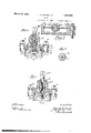
Figure 1 is a vertical sectional view of one form of my invention taken in a plane along the axis of the valve plug. Y
Figure 2 is a View showing details of construction of Figure 1 along lines 2 2.
Figure 3 is a modified structure for maintalning the valve plug in proper position.
Flgure 3a is a View similar to Figure 3 o a further alternative form of the invention.
Figure 4 is a vertical sectional view show- `ing details of construction of one form of my invention for supplying lubricant to the valve under pressure.
Figure 5is an end view of the compressorscrew arrangement shown in Figure 4.
Figure 6 shows a modified structure for supplying lubricant to the valve under pressure.
Figure 7 is a further alternative form of this invention.
Referring to the drawings, my invention comprises a valve body 10 having mounted therein a tapered plug 11. Body 10 is provided on its interior with an annular recess 10a to facilitate. the accurate machining of the valve seat and to prevent interference between the upper end of the plug 11 and the wall of body 10.
The plug 11 is provided on its upper end -with a tubular extension 11a which constitutes an operating stem for the plug.
The upper end of stem 11a may be suitably shaped for the application of a wrench or other instrument to facilitate the turning of the plug. rlhe plug 11 is [provided with a transverse opening 12 which constitutes the valve passage through which fluid passes when the passage 12 is brought to register with the pipe openings at either end of the valve. The body portion 10 is provided with two flanges 12a for the purpose of making pipe connections to the valve structure, only one iiange being shown in the drawings. The upper portion of the body 10 is provided with a iange 13 which is suitably coun-A terbored at 13a for the purpose of receiving a packing ring 14. The bottom of the counterbore 13a is so shaped that when pressure is applied upon ring 14, the ring tends to be forced against stem 11a. Surrnounting flange 18 is a' second flange 15 having formed thereon a gland 15a arranged to exert pressure upon the packing ring 14, pressure beting applied by means of-bolts 16. The end of gland 15a 1s so shaped that when pressure is applied upon packing ring 14 the ring is pressed tral opening of stem 11a is a compressor plug 18 which is secured in position by screw threads as at 18a. Plug 18 is provided with a suitable threaded central opening into which is screwed a compressor screw 186.
The threaded central opening in plug 1 8 con` stitutes a reservoir for a suitablelubricant for the valve'. The lower end of plug 18 is provided with a check-valve structure to prevent the egress of lubricant from the valvehousing and comprises a ball 19 and a spring 20 holding the ball in position over a passage communicating with the threaded opening 1n plug 18; the check-valve elements being held in position in plug 18 by means of a pin 21 pssing through the lower end of the plug 1 '.Ihe lower end of body 10 is 'provided with` la flange 22 which is suitably recessed at 22a for the reception of a cover plate 23 provided with a shoulder 23a adapted to enter the recess 22a. Interposed between the flange 22 and the plate 23 is a fieXible plate 24 which is securely clamped between the elements 22 and 23 by suitable bolts 25. The lower end of, plug 1,1 is provided with an .eX- tension 116 which is dove-tailed in cross-section, or is frusto-conical in shape with the large end extending downward. The plate 24 supports at its center a bearing element 25d having a complemental recess which engages and cooperates with the extension 116 on plug 11. The bearing element 25d is provided with a threaded stem 25a over which is threaded a nut 256 7for securing the bearing element to plate 24. A spring diaphragm 26 is located within a recess 236 formed in plate 23 and is provided with a central opening for the reception of the .lower end of the stem 25a of bearing element 25d. The relative location' of the various elements is such that the diaphragm spring 26 exerts upward pressure against stem 25a, which in turn transmits the pressure to the plug 11 to cause the plug member to be securely seated within thehousing.
The manner in which the extension 116 on plug 11 is inserted in bearing element 25d is illustrated in Figure 2. The bearing element 25d is provided on one side with a slot 250 machined to provide a snug fit in the bearing element 25d, only suficient clearance beingI allowed to permit free rotation of the eXtension within the bearing element when the plug is rotated. Any appreciable flexing of plate 24 will result in an axial movement of plug 11 by virtue of the connection between bearing element 25d and extension 116.
The operation of my invention is as follows: s
As previously stated, plug 11 is normally kept rightly seated within body 10 by the action of diaphragm spring 26 upon bearing element 25d. Preliminarily, screw 186 is removed from plug 18 and a suit-able fluid lubricant, such as grease, is introduced into the central opening of plug 18 byany suitable means such as a grease gun. The lubricant, under pressure, will fill the central opening of plug 18 and fiow past check-valve 19 into passages 17, 17a and 176. Since passages 17a and 176 communicate with the space be` tween the lower end of the plug 11 and plate 24 this space will become filled with lubricant. Also the annular recess 10a n'ear the top of body 10 vwill become filled with lubricant by leakage from between the surfaces of contact of the valve and seat. If desired, this preliminary filling of the valve with lubricant may be done before plate 24 is securely clamped to body 10 in order to permit the ready escape of air entrapped in the space between the plug 11 and plate 24, although this iS not essential for the reason that air will escape in any event when the plug is raised from its'seat.
=When bolts 25 are securely clamped, the seal between plate 24 and body 10 is sufiiciently tight to prevent the leakage of lubricant from the body. It will thus be seen that plate'24 constitutes a flexible wall portion of the body or housing of .the valve structure. After the valve structure has been completely filled with lubricant the Agrease gun is removed and screw 186 replaced. Upon forcing the screw 186 into plug 18 the lubricant is subjected to considerable pressure which is transmitted through the various passages to act upon the walls of the housing 10, including the fiexible plate 24. Since the vertical component of pressure of the lubricant upon plate 24 tends to cause a downward movement of the plate it will bev seen that the action of the pressure upon the plate is to opposev the action of diaphragm spring 26 and, therefore, tends to unseat plug 11. By proper adjustment ofthe pressure of the lubricant by means of screw 18b, a balance can be obtained between the action of plate 24 and spring 26 whereby the plug 11 will be unseated and held in proper spaced relation with respect to its seat, the intervening space being filled with lubricant.
If it be desired to increase the action -of plate 24 in unseating plug 11, it is only necessary to increase the effective area of plate 24 over which the pressure is applied. Obviously, this may be done by increasing the diameter of that portion of the plate which is exposed to pressure of the lubricant and is free to ex.
Instead of the frusto-conical shape of extension 11b employed in Figure 1, the extension may havetheA- form shown in Figure 3. In this form the extension has a short cylindrical body provided with a flat fillister head. The construction of Figure 3 is otherwise the same as that shown in Fi ures l and 2.
In Figure 4, I have s own the lubricant compressor arrangement of Figure 1 as applied to an alternative valve structure. Corresponding elements in these figures are rcpresented by the same reference characters. The valve structure in Figure 4 differs from that in Figure 1 only in the packing arrangement at tlie top` of plug 11 to prevent the escape of lubricant. In the arrangement of Figure 4. the packing ring is a plain cylindrical ring of suitable material which lies in a cylindrical recess formed partly in the casing 10 and partly in plug 11. It will thus be seen, that in case the ring 14 be made of resilient material, the application of pressure upon gland 15erI by means of screw 16 will compress the ring and tend tq unseat plug 11. In the arrangement shown in Figure 4, it will be seen that the lower end of plug 18 is reduced in diameter, in order that the ends of 'pin 21 may extend beyond the surface of the plug, and may be bradded if desired, without interference with the walls of the opening in which plug 18 yis inserted.
It is to be noted that the screw-compressor arrangement shown in Figures 1 and 4 is made in a unitary structure which greatly facilitates its removal for cleaning, repairing or renewal. This unitary arrangement of the compressor elements also greatly facilitates the assembly of the completed valve structure. permits of the introduction of a larger quantity of lubricant than in the casel where only a compression screw is employed.
Figure 5 is a view of the screw compressor assembly of Figure 1 as seen from the bottom end of the assembly. It will be noted that the upper end of plug 18 is provided with a portion in the form of a hexagonal nut to facilitate its assembly by means of a wrench.
Furthermore, this arrangement Figure 6 illustrates a modified structure of a screw compressor for forcing lubricant into the valve structure. Parts corresponding to those shown in Figures 1 and 4 are indicated by like numerals. In this rrangement, the check-valve structure is noti corporated as a unitary structure in plug 18, but is mounted within a small central opening in ste-m 11a. The seat for the ball 19, however, is formed on the lower end of plug 18. The structure of Figure 6, is otherwise the same as that of Figure 4.
It is understood that the structural embodiment of m invention may assume various forms. Ior example, it is within the scope of my invention to arrange the elements in such a manner that the plate 24a shown in Figure 3a, normally exerts an upper pressure on the plug 11b, thus permitting thehdiaphragm spring 26 to be dispensed .fwit
Having thus described my invention and illustrated its use what I claim as new and desire to secure by Letters Patent is:
1. In a`valve structure, the combination of a valve housing provided with a valve seat and avalve-ineinber havingengaging surfaces, means for supplying lubricant under pressure to the engaging surfaces of said valve and seat, and'means operable bythe pressure of said lubricant to cause said valve to partake of limited unseating movement,
2. In a valve structure the combination of a housing provided with a valve seat and a valve member having engaging surfaces, biasing means for holding said valve on its seat, means forsupplying lubricant under pressure to the engaging surfaces of said valve and seat, and means operable by the pressure of said lubricant to oppose said biasing means and cause limited unseating movement of said valve member.
3. In a valve structure, the combination of a valve housing provided with a valve seat and a valve member cooperating therewith, means for supplying lubricant under pressure to said housing, and means operable by the pressure of said lubricant to cause said valve to partake of limited unseating movement.
4. In a valve structure the combination of a housing provided with a valve seat anda valve member cooperating therewith, biasing means for holding said valve on its seat, means for supplying lubricant under pressure to said housing, and means operable by the pressure of said lubricant to oppose said biasl ing means and cause limited unseating move-v mentof said valve member.
5. In a valve structure the combination of a housing provided with a flexible wall portion and a valve seat, a valve seated upon said v seat each having engaging surfaces and se-L cured to said flexible wall portion, means-for supplying lubricant under pressure -between iso ' flexed and the .engaging surfaces of the valve and for subjecting the flexible Wall portion to pressure of the lubricant, whereby said wall por-l tion partakes of said valve.
6. A valve structure comprising a housing provided with la valve opening, a rotatable valve element mounted in said -housing and adapted to cover and uncover said opening, a flexible plate forming a'portion of the wall of said housing, said rotatable valve element being secured to said plate by an anchor bearing to permit free rotation of said valve and to cause said valve to partake of axial movement upon flexure of said plate a stem extending from the valve at the end opposite to said flexible plate, and lubricant containing means in said stem.
7. A valve structure comprising a housing provided with a valve opening, a rotatable valve element mounted in said housing and adapted to cover and uncover saidopening, a flexible plate forming a portion of the wall of said housing, said rotatable valve element being secured to said plate by an anchor bearing to permit free rotation of said valve and to cause said valve ,to partake of axial movement upon llexure of said plate and means for supplying lubricant under pressure to said housing whereby said plate becomes unseats said valve.
8. A valve structure comprising a housing provided with a valve opening, a rotatable valve element mounted in said housing and adapted to cover and uncover said opening, a flexible plate forming a portion of the Wall of said housing, said rotatablevalve element limited movementto unseat being secureddo said plate by an anchor bearing to permit free rotation of said valve, said plate being spaced vfrom said valve element anda portion of a side wall of said housing, and means for supplying lubricant under pressure to the space between said valve element and plate for establishing a sufficient vertical component of force between said plate and said side wall to flex the plate and thereby unseat said valve.
9. A valve structure comprising a housing provided with a valve opening, a rotatable valve elementmountedin said housing and adapted to cover and uncover said opening, a flexible plate forming a portion of the Wall of said housing, said rotatable valve element being secured to said plate by an anchor bearing to permit free rotation of' said valve and to cause said valve to partake of axial movement upon fleXure of said plate, said plate normally tending to hold said valve on its seat and `means for supplying lubricant under pressure to said housing whereby said plate is flexed against its normal tension and thereby unseats the valve.
10. .In a valve structure' the colnbination of a housing provided .with a flexible Wall portion and a valve opening, a rotatable valve seated vover said opening, means for securing said valve element to said flexible wall portion whereby said valve may be unseated by flexure of said wall but is free to be moved from over said opening, and a stem for rotating said valve extending from the end opposite to said flexible wall.
l1. A valve`structure comprising a housing provided With a valve opening, a rotat- \able valve element mounted in said housing and adapted to cover and uncover said open,- ing, a flexible plate forming a portion of the Wall of said housing, said rotatable valve element being secured to said plate by an anchor vbearing to permit free rotation of said valve yand to cause said valve to partake of axial movement upon ilexure of said plate, a removable closure for the valve housing having a portion engaging the periphery of the ilexib e plate for retaining. the same and forming a seal to prevent the escape of lubricant, and means for supplying lubricant under pressure to said housing whereby said plate becomes flexed and unseats said valve.
12. In a valve structure, in combination, a valve housing or casing member having a tapered valve seat, and a tapered valvemember engaging said seat, one of said members being provided with la transversely arranged groove adapted to receive lubricant for the surface of contact of the valve and casing, means for normally holding the said valve on its seat, means for lubricating said valve including a lubricant chamber and means therein for `forcing lubricant under pressure Apreliminarily to the surface of contact of said valve and seat adjacent to said chamber, thence to said transversely disposed groove,
. toY thereby distribute the lubricating fluid upon the adjacent surfaces of the valve and seat, and means separate from said lubricant chamber, for confining some of the lubricant thus placed under pressure for act-ing on one end of said valve for displacing it longitudivnally of its seat, such preliminary lubricating facilitating such displacement of the valve upon pressure of lubricant acting on said valve end.
13. Ina valve structure, in combination, a valve housing or casing member having a tapered valve seat, and a tapered valve member engaging said seat, one of said members being provided with a transversely arranged groove adapted to receive a lubricant for the surface offcontact of the valveand casing, means for normally holding the said valve on its seat,1m'e'ans at one end of the valve structure 'for lubricating said valve including a lubricant chamber and means therein for forcing lubricant under pressure preliminarily to the surfaces'of contact of said valve and seat adjacent to said chamber, thence Vto said transversely disposed groove, to thereby distribute the lubricating fluid upon the adjacent surfaces of the valve and seat, and
means located at the opposite end of the valve structure for confining some of the lubricant thus placed under pressure for acting on one endof said valve for displacing it lon itudinally ing facilitating such displacement of the valve upon pressure of. lubricant acting on said valve end.
14. In a device of the character describe/d, incombinatioh, a casing. having a passage- Way for iuid and a valve seat, a tapered valve member engaging said seat and lubricant passagevvays in the valve and casing, a lubricant chamber in said valve member communicating with said lubricant passagevvays, a compression chamber adjacent to said valve member and in communication with said lubricant chamber, and a pressure responsive element in said compression chamber for lifting the valve member from its seat upon compression of the lubricant in said compression chamber.
15. In a device of the character described, in combination, a casing having a passageway for fluid and a valve seat, a tapered valve member engaging said seat and lubricant passagevvays in the surface of contact of said valve and casing, a lubricant chamber in said valve member communicating with said lubricant passageways, a compression chamber adjacent to said valve member and in communication with said lubricant chamber, means for compressing the lubricant in both of said chambers, and a pressure responsive element in said compression chamber for lifting the valve member from its seat upon compression of the lubricant in said compression chamber.
16. In a device ofthe character described, in combination, a valve housing or Y casing having a valve seat, and a valve member engaging said seat, means for normally holding said valve on its seat, means for lubricating said valve by forcing lubricant under pressure thereto, and means operated by said pressure and acting on one end of said valve for lifting it from its seat. l
17. In a valve structure, a body member having an inflow and an outflow passage, a tapered plug rotatable within said body and having a port adapted to register with said passages when the. plug 'is in open position, said valve structure having a lubricant receiving chamber in its larger end, means independent of said lubricant receiving chamber for placing lubricant under pressure in said valve structure, means for lubricating the surfaces of contact of the valve and casing including longitudinally and transversely arranged grooves in said surfaces of contact, said transverse groove being located at the smaller end of the valve member adjacent to said means for placing said lubricant under pressure and being in communication with said chamber through said longitudinal of its seat, suchv preliminary lu ricat-y surface of contact of saidv member,
groove, means for conducting the lubricant to said surfaces under pressure preliminarily adjacent to the means for placing the lubricant under pressure, and thence to said transverse groove whereby to initially lubricate said surfaces.
18. In a valve structure, a body member having an inflow and an outflow passage, a tapered plug rotatable Within said body and having a port adapted to yregister with said passages when the plug is 1n open position,
said valve structure having a lubricant receiving chamber at one end, means at the opposite end of said valve structure for placing lubricant under pressure in said valve structure, means for lubricating the surface of contact of the valve and casing including longitudinally and transversely arranged grooves in said surface of contact, said transverse groove beinglocated adjacent to said means for placing said lubricant under pressure and so arranged that lubricant under pressure therein'will tend to move the valve relatively to its seat, said groove being in communication with said chamber'through said longitudinal groove, means for preliminarily conducting the lubricant to said surfaceadjacent to the means for placing the lubricant under pressure, and thence under pressure to said transverse groove whereby to initially lubricate said surface and to tend to move the valve relatively to its seat.
19. In a valve structure, a valve casing having a tapered valve seat, a tapered valve member engaging said valve seat'and grooves for conducting lubricant to the seating. surfaces thereof, means at the smaller end of the valve seat for introducing lubricant into said grooves, a chamber for fluid at the larger end of said lvalve seat, a movable diaphragm in said chamber connected to said valve member, yieldingly resistant means tending to move the diaphragm and thereby said valve member onto its seat and permitting movement thereof in another direction in response to pressure established in said chamber by the introduction of lubricant into said chamber through said grooves.
20. In a plug valve, in combination, a casmg having a tapered valve s eat, a rotatable tapered valve member engaging said seat, a
chamber at one end of said valve seat, a swivel plate in said chamber engaging said valve and a flexible diaphragm connecting said plate to a part of said casing, said diaphragmgbeing of greater effective areathan the adjacent end of said valve member so that pressure established in said chamber acting between the'diaphragm and casing will cause the valve to be moved from its seat, said diaphragm normally tending. to hold the valve on its seat. f
21. In a valve structure, in combination, a casing having aI tapered valve seat, a chamber adjacent to said valve seat, a tapered valve member engaging said seat, a diaphragm in said chamber positively connected to said valve member, and yieldingly resistant means `acting upon and tending to move said diaphragm in one direction to hold the valve on its seat, said diaphragm being substantially immovable normallyin theI opposite direcp tion, but responsive to lubricant pressure to move said valve.
10 22. In a valve structure, in combination, a
casing having a tapered valve seat, a. chamber adjacent to said valve seat, a tapered valve member engaging said seat, a diaphragm in said chamber connected to said valve member, and means for introducing lubricant under pressure into said chamber to act against said diaphragm for moving said valve relatively to its seat.
In Witness whereofl have hereunto signed 520 my name. f
.. JESSE C. MARTIN, JR.
Priority Applications (1)
| Application Number | Priority Date | Filing Date | Title |
|---|---|---|---|
| US24399227 US1851259A (en) | 1927-12-31 | 1927-12-31 | Valve |
Applications Claiming Priority (1)
| Application Number | Priority Date | Filing Date | Title |
|---|---|---|---|
| US24399227 US1851259A (en) | 1927-12-31 | 1927-12-31 | Valve |
Publications (1)
| Publication Number | Publication Date |
|---|---|
| US1851259A true US1851259A (en) | 1932-03-29 |
Family
ID=22920959
Family Applications (1)
| Application Number | Title | Priority Date | Filing Date |
|---|---|---|---|
| US24399227 Expired - Lifetime US1851259A (en) | 1927-12-31 | 1927-12-31 | Valve |
Country Status (1)
| Country | Link |
|---|---|
| US (1) | US1851259A (en) |
Cited By (3)
| Publication number | Priority date | Publication date | Assignee | Title |
|---|---|---|---|---|
| US2483518A (en) * | 1945-02-03 | 1949-10-04 | Duriron Co | Plug cock valve |
| US2501946A (en) * | 1945-01-05 | 1950-03-28 | Duriron Co | Plug cock valve |
| US2501945A (en) * | 1944-03-31 | 1950-03-28 | Duriron Co | Plug cock valve |
-
1927
- 1927-12-31 US US24399227 patent/US1851259A/en not_active Expired - Lifetime
Cited By (3)
| Publication number | Priority date | Publication date | Assignee | Title |
|---|---|---|---|---|
| US2501945A (en) * | 1944-03-31 | 1950-03-28 | Duriron Co | Plug cock valve |
| US2501946A (en) * | 1945-01-05 | 1950-03-28 | Duriron Co | Plug cock valve |
| US2483518A (en) * | 1945-02-03 | 1949-10-04 | Duriron Co | Plug cock valve |
Similar Documents
| Publication | Publication Date | Title |
|---|---|---|
| US1443675A (en) | Valve | |
| US2185991A (en) | Tappet construction | |
| US1851259A (en) | Valve | |
| US2058747A (en) | Valve | |
| US2356738A (en) | Pump | |
| US1146723A (en) | Combined stop and relief valve. | |
| US1510528A (en) | Valve | |
| US2917273A (en) | Gear-actuated reciprocating valve construction | |
| US1403756A (en) | Self-lubricating angle cock | |
| US2145628A (en) | Lubricated valve for low pressures | |
| USRE19399E (en) | Valve | |
| US3500958A (en) | Flow responsive valve for lubricating systems | |
| US1998029A (en) | Automatic lubricated gas stop | |
| US3430658A (en) | Flow control valve | |
| US1530924A (en) | Slush-pump valve | |
| US2616657A (en) | Lubricated valve | |
| USRE17724E (en) | Valve | |
| US712350A (en) | Valve. | |
| US1887969A (en) | Spray gun | |
| US2191815A (en) | Lubricated tank valve | |
| US2155558A (en) | Pressure regulator | |
| US2872937A (en) | Valve assembly | |
| US2247099A (en) | Faucet | |
| US667148A (en) | Lubricator. | |
| US90371A (en) | Improvement in steam-engine lubricators |