US1851258A - Controlling device for coin operated musical instruments - Google Patents
Controlling device for coin operated musical instruments Download PDFInfo
- Publication number
- US1851258A US1851258A US106221A US10622126A US1851258A US 1851258 A US1851258 A US 1851258A US 106221 A US106221 A US 106221A US 10622126 A US10622126 A US 10622126A US 1851258 A US1851258 A US 1851258A
- Authority
- US
- United States
- Prior art keywords
- controlling
- switch
- objects
- section
- guide
- Prior art date
- Legal status (The legal status is an assumption and is not a legal conclusion. Google has not performed a legal analysis and makes no representation as to the accuracy of the status listed.)
- Expired - Lifetime
Links
- 230000001276 controlling effect Effects 0.000 description 106
- 238000005096 rolling process Methods 0.000 description 28
- 230000000903 blocking effect Effects 0.000 description 6
- 239000012298 atmosphere Substances 0.000 description 3
- PXHVJJICTQNCMI-UHFFFAOYSA-N Nickel Chemical compound [Ni] PXHVJJICTQNCMI-UHFFFAOYSA-N 0.000 description 2
- 238000010276 construction Methods 0.000 description 2
- 238000007599 discharging Methods 0.000 description 2
- 238000004519 manufacturing process Methods 0.000 description 2
- 101100460200 Saccharomyces cerevisiae (strain ATCC 204508 / S288c) NEW1 gene Proteins 0.000 description 1
- 101100273916 Schizosaccharomyces pombe (strain 972 / ATCC 24843) wip1 gene Proteins 0.000 description 1
- 102000004338 Transferrin Human genes 0.000 description 1
- 108090000901 Transferrin Proteins 0.000 description 1
- 230000000694 effects Effects 0.000 description 1
- 238000011010 flushing procedure Methods 0.000 description 1
- 229910052759 nickel Inorganic materials 0.000 description 1
- 230000008520 organization Effects 0.000 description 1
- 239000012581 transferrin Substances 0.000 description 1
Images
Classifications
-
- G—PHYSICS
- G07—CHECKING-DEVICES
- G07F—COIN-FREED OR LIKE APPARATUS
- G07F17/00—Coin-freed apparatus for hiring articles; Coin-freed facilities or services
- G07F17/30—Coin-freed apparatus for hiring articles; Coin-freed facilities or services for musical instruments
Definitions
- This invention relates to the coin-actuated devices used for controlling the operation of player pianos and other automatic musical instruments as well asautomatic machines of various kinds.
- One of the objects of my invention is the production of a strong, compact and durable of this character which is not liable to get out of order.
- Another object is to so construct it that the parts require no fine work or close fitting, thus guarding against binding or clogging and insuring the free and proper operation of the device at alltimes.
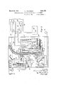
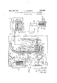
- Figure 1 is a sectional side elevation, partly diagrammatic, of the improved device with its cover removed, showing its normal condition before any coins have been deposited.
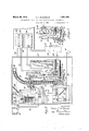
- Figure 2 is a similar view, showing the position of the parts when a single coin is deposited.
- Figure 3 is a fragmentary sectional view, showing'the position of the parts upon the completion'of a selection of the note sheet.
- Figure 4 is a view similar to Figure 2, showing the position of the parts when a plurality of coins have been deposited and after the completion of a given selection.
- Figure 5 is a cross section on line 55, Fig. 1.
- the device comprises a guide or race containing a series of balls or other rolling objects adapted to circulate through it; coin controlled mechanism for moving the balls through therace, and mechanism controlledby the balls for opening the motor-switch of a musical instrument or actuatingor controlling any other desired part or machine.
- the electric motor 10 is provided with a switch 11 of any suitablekind, the knifeblade type being preferred.
- the lever 12 of this switch has a spring 13 which tends preferably consists of tubes or tube-sections constantly to close" it to establish the motor circuit.
- This lever is released whenever a- J propercoin is deposited in thechute 14 of the device.
- the releasing means comprises a solenoid 15 Whose core controls the switch lever through anelbow lever 16 and a catch bar 17 having a nose 19 which normally interlocks with a pin 20 projecting from the rear wall ofthe scribed.
- the lower arm of the elbow lever 16 isprovided with a laterallyprojecting lug 23 which trips the catch bar off the pin 20 every time said lever is rocked by the descent of the solenoid core.
- This lever is returned to its normal position bya' spring 2 1.
- the section 25 being afeed tube or magazine for the balls 28, the section 26 being a controlling section for the parts i which in turn control the motor-switch or its equivalent, and the other tube 27 acting as a return-section for the balls, and being a part of the magazine section.
- the magazine tube is preferably curved .to oneside to shorten it and make the device -more compact, and its upper end is open to receive the balls in assembling the device, the column of balls being-confined by a cotter 32 or other'means.
- the lower ends of said 199 tubes are secured in a similar block 33 and communicate by a passage consisting preferably of a vertical branch 34 forming a con tinuation of the controlling tube 26, and a curved branch 35 leading into the lower end of the return tube 27.
- a passage consisting preferably of a vertical branch 34 forming a con tinuation of the controlling tube 26, and a curved branch 35 leading into the lower end of the return tube 27.
- In the bottom of the block 33 is an opening 36 leading to the lower end of the curved branch 35; and passing through this openingis the nose of a detent 37 which normally extends into the path of the balls of that curved branch and prevents them from rolling back into the vertical branch 34.
- This detent is pivoted to swing
- the balls as they descend into the vertical passage 31 of the upper block 30, are transferred or displaced into the top of the controlling tube 26 by an ejector or plunger 39 having an opening 39 just large enough and deep enough to freely receive one of the balls, as shown in Fig. 1. Upon the forward stroke of this plunger, that ball falls into the controlling tube and rests on the right hand side of the detent 37.
- the plunger 39 is actuated by the solenoid 15, and for this purpose is pivoted to the lower arm of the elbow lever 16, whereby it is advanced every time the solenoid is energized by the deposit of a coin.
- the plunger carries the balls successively from the lower end of the magazine tube 25 or the upper end of the return tube 27 into the controlling tube 26 in which latter they pile up, as shown in Fig. 4, each transferred ball representing or corresponding to a deposited coin of the proper denomination.
- the several tubes and their connecting passages are of the proper diameter to freely receive the balls, preferably with a clearance of a sixty-fourth of an inch.
- the halls dropped into the controlling tube 26 are successively transferred into the lower end of the return tube 27 by a second plunger or ejector 40 guided in a horizontal passage '41 which intersects the vertical passage 34 and joins the curved passage 35 of the block 33.
- This plunger when in its rearward position, clears the front end of the guide passage 41, allowing a ball to occupy it, while upon its forward stroke, it pushes said ball past the yieldable detent 37 into said curved passage against the lower end of the column of balls in the return tube, raising that column a distance equal to the diameter of the balls.
- the nose of the detent Upon the retraction of this plunger, the nose of the detent returns to its former sition and checks the return of the balls into the bottom of the controlling tube.
- the head of the plunger 40 is provided in its under side with a longitudinal groove or recess 40" large enough to receive the nose of said detent on its forward stroke so as not to trip the detent out of the way, but effect such tripping by the transferred balls alone, thus permitting its prompt return and reliably retaining the transferred balls in the return-branch 27 of the ball-race.
- the plunger 40 is actuated by the arm 42 carried by the movable board of a pneumatic 43 which is controlled by the usual stop or trip perforations cut in the note sheet 44 at the ends of its selections, one of these being shown at 45.
- a suitable valvemechanism preferably in the form of a so-called unit valve-block 46 controls the connection between the stop-duct 47 of the tracker bar 48 and said block.
- This block is shown in section in Fig. 4, and contains the usual valve chamber 49 communicating with the exhaust chamber 50 by a port 51 and with the atmosphere by a port 52 which ports are controlled by the usual valves 53, 54, ac-
- the switch lever 11 is automatically opened at predetermined times by a pneumatic 59 whose movable member carries an arm 60 arranged to trip a pin 61 of the catch bar 17 when this pneumatic is collapsed, this bar having an inclined face 6:2 immediately below its nose which deflects the latter out of engagement with said pin when the bar is ber 64 of the block by a conduit 65.
- 66 in' dicates a valve-block containing an atmospheric duct 67 with which the diaphragm chamber 68 of the unit block 63 is connected by a conduit 69.
- the mouth of this duct is controlled by a suitable valve 70, preferably a pallet carried by a spring-stem 71 which tends to hold it shut.
- This valve is opened by a pallet lever 72 pivoted to the upper plunger-block 30 at 73 and having a trip pin 74 arranged to engage the upper end of the valve-stem when the lever is swung toward the adjacent controlling tube 26.
- the movement of the lever is effected by a push rod 75 guided in the lower plunger block 33 and attached at its rear end to the arm of the pneumatic 43, so that upon collapse of the latter, the push rod engages the lower portion of said lever and causes it to open the duct 67, thereby admitting atmosphere under the diaphragm of the unit block 63 and moving its valves to the proper position to cause collapse of the switch-opening pneumat c 59.
- the pallet-spring 71 closes the pallet and returns the pallet-lever to its former position by engagingits pin 74.
- This spring is still enough to compel the rod to travel forward with said arm when there is only one ball in the controlling tube, and yet light enough to yield and allow the arm to slide forward'on-the rod when the palletlever is blocked by a plurality of balls.
- This spring must be somewhat stronger than the pallet-spring 71 so that when the pushrod spring is compressed by the collapse of the pneumatic 43, it will compel the pushrod to advance with the arm of said pneumatic and overcome the resistance of the pallet spring.
- the operation of the device is as follows hen it is idle,the parts are in theposition shown in Fig. l, the motor switch 11 being-open and the pneumatics 4.3 and 59 inflated.
- the pallet-lever 72 is withdrawn, allowing the 'pallet'TO to remain closed@
- the upper and lower ejectors 39 and 40 and the push rod 75 are withdrawn.
- Both sections 25, 27 of themagazine tube are filled with balls and the controlling tube 26 is empty.
- the'solenoid 15 isenergized andits core is lowered, actuating the upper ball-ejector 39 which pushes one oftheballs in the magazine into the controlling tube 26, the ball dropping in front of the lower eject or 4:0, as shown in Fig. 2.
- the elbow lever 16 trips the catch bar 17 out of engagement with the fixed pin 20, letting it and the switch lever 11 descend under the tension of the spring 13, closing the switch and starting themotor of the instrument.
- the corresponding stop or trip perforation 45 registers with the companion tracker duct 47, causing, the transferpneumatic 43 to collapse and advancing the lower ejector 40 and the push rod 7 5.
- This ejector transfers the single ball lying in the controlling tube into the bottom of the return tube27.
- the push rod swings the lower arm of the pallet lever 7 2 into the controlling tube, as shown in Fig. 3, causing the leverpin 74 to open the pallet, whereupon atmos phere is admitted under the diaphragm of the valve block 63, collapsing the swit'ch-open- 1 ing pneumatic 59, opening the switch and stopping the instrument.
- the latter is provided with properly-spaced stop-shoulders 78 arranged on opposite sides of a stop '79 carried by the lower block, these shoulders being conveniently formed by a notch 80 in the upper side of the plunger, as shown.
- This simple, expedient construction does away with separate stopscrews for this purpose and predetermines the stroke of said pneumatic and the plunger, so that after once assembling the parts, they require no adjustment of any kind.
- this controlling device While possessing the desired strength, compactness and durability, this controlling device is absolutely positive in action, insuring the playing of one selection for one proper coin, and no more or less, or the delivery of one unit of other value for each coin depos ited,
- a controlling device of the character described the combination of a guide, a series of rolling objects in said guide, a switch, means actuated by the deposit of a coin for controlling the movement of the objects in one direction through the guide and for closing said switch, means for controlling the movement of the objects in the opposite direction through the guide, and means controlled by the objects for opening the switch.
- a controlling device of the character described the combination of a guide, a series of rolling objects in said guide, a switch, means actuated by the deposit of a coin for controlling the movement of the objects in one direction through the guide and for closing said switch, and means for controlling the movement of the objects in theopposite direction through the guide and for governing the opening of said switch. said objects acting to prevent the opening of the switch in a predetermined position thereof in said guide.
- a controlling device of the character described the combination of a guide, a series of rolling objects in said guide, a switch, means actuated by the deposit of a coin for controlling the movement of the objects in one direction through the guide and for closing said switch, means for opening said switch, and means for controlling the movement of the objects in the opposite direction through the guide and for governing said switch-opening means, said objects acting to render the switch-opening means inoperative in a predetermined position thereof in the guide.
- a controlling device of the character described the combination of a guide includ ing amagazine-sectio'n and a controllingsection communicating with each other at one end, a series of rolling objects in said magazine-section, a switch, and means for transferring the objects successively from said magazine-section into the mouth of said controlling-section and from the latter into the communicating end of the magazine-section, said means including parts for controlling the closing and opening of said switch, respectively, said objects acting to render the switch-opening part inoperative when there are a predetermined number of objects in the controlling section of the guide.
- a controlling device of the character described the combination of a guide having an opening, a movable member adjacent to said opening, rolling objects in said guide adapted to block the movement of said member in one position of the objects and to permit its movement in another position thereof, a switch, means for controlling the movement of the objects through the guide and for closing said switch, and means controlled by the movable member and said objects for opening the switch.
- a controlling device of the character described the combination of a guide having an opening, a movable member adjacent to said opening, rolling objects in said guide adapted to block the movement of said memher in one position of the objects and to permit its movement in another position thereof, a switch, means for controlling the movement of the objects through the guide and for closing said switch, and pneumatic mechanism controlled by said movable member for opening the switch.
- a controlling device of the character described the combination of an endless race having controlling and return sections, rolling objects in said race, a switch, means for controlling the movement of the objects from the return section to the controllingsection of the race and for closing said switch, means for transferring the objects successively from the controlling-section into the returnsection, a normally-free movable member adjacent to said controlling-section arranged to be blocked against movement by some of the'objects in the" controlling-section, and means controlledby said movable member;
- a controlling device of the character described, the combination of an endless race having controlling and return sections, a switch, means for moving the objects from the I return-section to the controlling-section of the race and for closing said switch, means for transferring the objects successively from the controlling-section into the return-section, a normally-free movable member adj acent to said controllingsection arranged to be blocked against movement by some of the objects in the controlling-section, unitary means for actuating said transfer meansand said movable member, and meanscontrolled 1 by said movable member for opening the switch.
- a switch for moving theobjects from one part of the gulde to another and for closing said switch, an e ector forreturmng the objects from the last-named part of the guide to the first-named part thereof, a normally-free movable member adjacent to said guide for governing the opening of the switch and arranged to be blocked against movement by some-of the rollingobjects, said swltch being prevented from closing when its governing member is thus blocked, a pushrod for actuating said movable member, and
- a -switch, a guide, rolling obj ects the push-rod is blocked by said objects.
- a normally-free movable -member adj acent to said guide for governing the opening of the switch and arranged to be blocked against movementby some of the rolling obto the push-rod.
- guide havin magazine and controlling secguide having communicating magazine and controlling sections, means for transferring the objects from the magazine-section into the mouth of the controlling-section and for closing said switch, transfer means at the dischargeqend of the controlling-section, a yieldable detent extending into the guide at said discharge end to check the return 'of the transfer-red: objects into the controlling-section,
- the combination'ofa switch a guide having an upright-controlling section provided with a longitudinal slot and a magazine-section com'municatingwith the lower end of sa d,controlllng-sectlon, rolling obects in sa d IllflgflZlIlG-SGCHOII, means for transferring the objects from the latter into the upper end'of the controlling-section and for closing said switch, means for ejecting the rolling objects'successively at the dis-fcharge end of said controlling-section, a leveractuated by said ejecting means having a part arranged in said slot and adapted to be blocked against movement when two or more objects are in said controlling-section, the lever being free for actuation by the ejecting means when there is but one object in the section, and pneumatic mechanism controlled by said lever for opening the switch, including a duct and a co-operating valve controlled by said lever.
- a controlling device of the character described the combination of a switch, a guide having an upright controlling-section provided with a longitudinal slot and a magazine containing rolling objects in communication with said section, means for ejecting the objects one at a time from said magazine 7 into said section and for closing said switch,
- a tubular race comprising a controlling-section and a magazine-section communicating therewith and including a feed tube, rolling objects in said race, means for transferring the objects from the feed tube to the controlling-section, means for ejecting the objects from the latter into the communicating end of the magazine-section, a part to be actuated for movement to an operative or inoperative position and controlled by said transferring means and said ejecting means, respectively, and means actuated by said ejecting means and movable into and out of the controlling section of the race for governing the movement of said part to its I inoperative position, said governing means being blocked against movement to maintain said part operative when there are a certain number of objects in the controlling section of the race and being free for movement when there are a less number of objects in said race-section to actuate said part to its inoperative position.
- a controlling device of the character described the combination of a switch, a movable member controlling the opening of the switch, a tubular race comprising a controlling-section and a magazine-section communicating therewith and having a laterallycurved feed tube, rolling objects in said race means for transferring the objects from said feed'tube tothe controlling-section, and means for ejecting the objects from the latter into the communicating end of the magazine-section, said switch-opening member being disposed adjacent to said controlling-section and connected with said ejecting means to be actuated thereby, the transferrin means governing the movement of said switch to its closed position and the switch-opening member in conjunction with the objects in the controlling section of the race governing the movement of the switch to its open position.
- a controlling device for automatic musical instruments and the like comprising a switch, a guide including two communicating-sections, rolling objects in the guide, means for transferring the objects from one section of the guide into the other and for closing said switch, means for returning the objects from said last-named guide-section to the first-named section, and a movable member controlling the opening of said switch and adapted to extend into said lastnamed guide-section, the rolling objects in the latter controlling said movable member to block its movement in one position of the objects so as not to affect the switch and permit its movement in another position to open the switch.
- a controlling device for automatic musical instruments and the like comprising a switch, a guide having an opening, a movable member controlling said switch and arranged adjacent to said opening, rolling objects in the guide adapted to block the movement of said member in one position of the objects and to permit its movement in another position, means for shifting said objects into and out of their blocking position, and means controlled by said shifting means for governing the closing and opening of the switch.
- a controllingdevice of the character described the combination of a part to be actuated, a guide, means for delivering rolling objects to said guide, said delivering means controlling the movement of said actuatable part to its operative position, means for discharging the objects from said guide, and means operable conjointly with said discharging means for controlling the movement of the actuatable part to its inoperative position, said controlling-means being operable to affect said part, only when there is a predetermined number of objects in the guide.
- said means being rendered inactive when there is more than one object in the controlling-section of the guide and rendered active to actuate said part when there is but one object in each section;
- a controlling device of the character described the combination of an endless race shaving controlling and return sections, rollin'g objects in said race, an ejector for transferring the objects successively from the cona trollin section into the return section means for transferring the objects from thereturn section to the controlling section, a normallyfree member adjacent to said controlling section arranged to be blocked against movement by some of the rolling objects inathe controlling section, pneumatic switch-actuating mechanism controlled by said movable member, a push rod fora'ctuating'said member, and a pneumatic for actuating said ejector and said push rod, 7 I
- a tubular race comprising communicating upper and lower' magazine-sections and a controlling section having its mouth arranged adjacent, to the junction of said magazine sections,said con trolling section communicating at its lower end with the lower magazine section rolling objects arranged in said race, and means for transferring the objects successively from said magazine sections into the mouth of sald controlling section and from the discharge end of the controlling section into the bottom of the lower magazine-section, said firstnamed transfer means controlling the movement of the actuatable part to its operative position 7 and said second-named transfer means and the objects in the controllingsec tion of said race controlling the movement of said part to its inoperative position;
- magazineand controlling tubes arranged side by side and having open upper ends secured in said blocks, rolling objects in said race, a. plunger guided in the upper block for feeding the objects from said magazine tube into the upper end of said controlling tube and for closing said switch, a second plunger guided in'said lowerblock for returning the objects from the lower endof the controlling tube into the-bottom of the magazine-tube,
- switch actuating means controlled by the objects in the controlling tube, saidmeans being rendered active or inactive to open the switch depending on'thenumber of objects in said controlling tube.
- a switch-operating mechanism comprising a switch, means fore-losing the switch, 7 a ball-race having an openingin its side, a series of balls traversingsaid race, means for moving theballs in the race, and a'switchopening member registering with said raceopening, the balls whenv opposite said opening blocking the movement of'said member to 'switch-openingposition, while permitting switch-opening means and in another position clearing the same to permit opemng of a as such movement when they move beyond said member.
- a controlling device for automatic musical instruments and the like comprising a switch, means for closing the switch, a guide having an opening, a movable member controlling said switch and arranged adjacent to said opening, movable objects in the guide adapted to block the movement of said member in one position of the objects and to permit its movement in another position, means for shifting said ob'ects into blocking position, means for shi ting said objects out of their blocking position, and means controlled j by said last named means for governing the opening of the switch.
Landscapes
- Engineering & Computer Science (AREA)
- Multimedia (AREA)
- Physics & Mathematics (AREA)
- General Physics & Mathematics (AREA)
- Pinball Game Machines (AREA)
Description
F. L. M CORMICK 1,851,258
CONTROLLING DEVICE FOR COIN OPERATED MUSICAL INSTRUMENTS March 29, 1932.
3 Sheets-Sheet Filed May 3, 1926 v I l l l JZi-bings.
March 29, 1932. F. M CORMlCK CONTROLLING DEVICE FOR COIN OPERATED MUSICAL INSTRUMENTS Filed May 5, 1926 3 SheetS- -Sheet J71 z)en for;
vmww w V w fiwwww MarchZQ, 1932. MCCORMICK 1,851,258
CONTROLLING DEVICE FOR COIN OPERATED MUSICAL INSTRUMENTS Filed May 3, 1926 3 Sheets-Sheet R w O mm 1 g Patented Mar. 29, 1932 UNITE-D srArss PAT NT OFFICE;
FRANK LQMCGORMIOK, or NORTH TONAWANDA, EwYo K, As'sIeNo T 'rnn u- DOLPH woRLrrzER MANUFACTURING ooMrANY, or, NORTH'TONAWANDA,NEW1,
YORK, A CORPORATION OF NEW-YORK- GONTROLLI G DEVICE roR coIN OPERATED MUsIoALrNsrRUNtEN'rs Application filed Ma 3, 1926. I Serial Nb. 1065,221. V
This invention relates to the coin-actuated devices used for controlling the operation of player pianos and other automatic musical instruments as well asautomatic machines of various kinds.
I One of the objects of my invention is the production of a strong, compact and durable of this character which is not liable to get out of order.
Another object is to so construct it that the parts require no fine work or close fitting, thus guarding against binding or clogging and insuring the free and proper operation of the device at alltimes.
I In the accompanying drawings:
Figure 1 is a sectional side elevation, partly diagrammatic, of the improved device with its cover removed, showing its normal condition before any coins have been deposited. Figure 2 is a similar view, showing the position of the parts when a single coin is deposited. .Figure 3 is a fragmentary sectional view, showing'the position of the parts upon the completion'of a selection of the note sheet. Figure 4 is a view similar to Figure 2, showing the position of the parts when a plurality of coins have been deposited and after the completion of a given selection. Figure 5 is a cross section on line 55, Fig. 1.
Similar characters of reference indicate corresponding parts throughout the several views.
In its general organization, the device comprises a guide or race containing a series of balls or other rolling objects adapted to circulate through it; coin controlled mechanism for moving the balls through therace, and mechanism controlledby the balls for opening the motor-switch of a musical instrument or actuatingor controlling any other desired part or machine.
In the drawings, the improvement is shown as applied to an automatic musical instrument, such as an electric player piano, but it is also applicable to other coin-controlled machines or devices. p p
The electric motor 10 is provided with a switch 11 of any suitablekind, the knifeblade type being preferred. The lever 12 of this switch has a spring 13 which tends preferably consists of tubes or tube-sections constantly to close" it to establish the motor circuit. This lever is released whenever a- J propercoin is deposited in thechute 14 of the device. In its preferred embodiment, the releasing means comprises a solenoid 15 Whose core controls the switch lever through anelbow lever 16 and a catch bar 17 having a nose 19 which normally interlocks with a pin 20 projecting from the rear wall ofthe scribed. I
As shown in Fig. 1, the lower arm of the elbow lever 16 isprovided with a laterallyprojecting lug 23 which trips the catch bar off the pin 20 every time said lever is rocked by the descent of the solenoid core. This lever is returned to its normal position bya' spring 2 1. r a
The guide or ball-race, before referred to,
25, 26 and 27 the section 25 being afeed tube or magazine for the balls 28, the section 26 being a controlling section for the parts i which in turn control the motor-switch or its equivalent, and the other tube 27 acting as a return-section for the balls, and being a part of the magazine section. The tubes 26 and 27 are preferably arranged side by side and are connected at their upper ends by a horizontal passage 29 formed in a fixed block: 30 in which they are secured. This block, also has a -vertical=passage 31 of the size of the balls, which registers with the opposing ends of the magazine and return tubes 25, 27. The magazine tube is preferably curved .to oneside to shorten it and make the device -more compact, and its upper end is open to receive the balls in assembling the device, the column of balls being-confined by a cotter 32 or other'means. The lower ends of said 199 tubes are secured in a similar block 33 and communicate by a passage consisting preferably of a vertical branch 34 forming a con tinuation of the controlling tube 26, and a curved branch 35 leading into the lower end of the return tube 27. In the bottom of the block 33 is an opening 36 leading to the lower end of the curved branch 35; and passing through this openingis the nose of a detent 37 which normally extends into the path of the balls of that curved branch and prevents them from rolling back into the vertical branch 34. This detent is pivoted to swing vertically and held in normal position by a sprin 38.
The balls, as they descend into the vertical passage 31 of the upper block 30, are transferred or displaced into the top of the controlling tube 26 by an ejector or plunger 39 having an opening 39 just large enough and deep enough to freely receive one of the balls, as shown in Fig. 1. Upon the forward stroke of this plunger, that ball falls into the controlling tube and rests on the right hand side of the detent 37.
The plunger 39 is actuated by the solenoid 15, and for this purpose is pivoted to the lower arm of the elbow lever 16, whereby it is advanced every time the solenoid is energized by the deposit of a coin. The plunger carries the balls successively from the lower end of the magazine tube 25 or the upper end of the return tube 27 into the controlling tube 26 in which latter they pile up, as shown in Fig. 4, each transferred ball representing or corresponding to a deposited coin of the proper denomination. The several tubes and their connecting passages are of the proper diameter to freely receive the balls, preferably with a clearance of a sixty-fourth of an inch.
The halls dropped into the controlling tube 26 are successively transferred into the lower end of the return tube 27 by a second plunger or ejector 40 guided in a horizontal passage '41 which intersects the vertical passage 34 and joins the curved passage 35 of the block 33. p This plunger, when in its rearward position, clears the front end of the guide passage 41, allowing a ball to occupy it, while upon its forward stroke, it pushes said ball past the yieldable detent 37 into said curved passage against the lower end of the column of balls in the return tube, raising that column a distance equal to the diameter of the balls. Upon the retraction of this plunger, the nose of the detent returns to its former sition and checks the return of the balls into the bottom of the controlling tube.
As shown in Figs. 1 and 5, the head of the plunger 40 is provided in its under side with a longitudinal groove or recess 40" large enough to receive the nose of said detent on its forward stroke so as not to trip the detent out of the way, but effect such tripping by the transferred balls alone, thus permitting its prompt return and reliably retaining the transferred balls in the return-branch 27 of the ball-race.
The plunger 40 is actuated by the arm 42 carried by the movable board of a pneumatic 43 which is controlled by the usual stop or trip perforations cut in the note sheet 44 at the ends of its selections, one of these being shown at 45. A suitable valvemechanism, preferably in the form of a so-called unit valve-block 46 controls the connection between the stop-duct 47 of the tracker bar 48 and said block. This block is shown in section in Fig. 4, and contains the usual valve chamber 49 communicating with the exhaust chamber 50 by a port 51 and with the atmosphere by a port 52 which ports are controlled by the usual valves 53, 54, ac-
tuated by the customary diaphragm 56 wl1cn-.
ever atmospheric pressure is admitted to the diaphragm chamber 57 through the port 58.
The switch lever 11 is automatically opened at predetermined times by a pneumatic 59 whose movable member carries an arm 60 arranged to trip a pin 61 of the catch bar 17 when this pneumatic is collapsed, this bar having an inclined face 6:2 immediately below its nose which deflects the latter out of engagement with said pin when the bar is ber 64 of the block by a conduit 65. 66 in' dicates a valve-block containing an atmospheric duct 67 with which the diaphragm chamber 68 of the unit block 63 is connected by a conduit 69. The mouth of this duct is controlled by a suitable valve 70, preferably a pallet carried by a spring-stem 71 which tends to hold it shut. This valve is opened by a pallet lever 72 pivoted to the upper plunger-block 30 at 73 and having a trip pin 74 arranged to engage the upper end of the valve-stem when the lever is swung toward the adjacent controlling tube 26. The movement of the lever is effected by a push rod 75 guided in the lower plunger block 33 and attached at its rear end to the arm of the pneumatic 43, so that upon collapse of the latter, the push rod engages the lower portion of said lever and causes it to open the duct 67, thereby admitting atmosphere under the diaphragm of the unit block 63 and moving its valves to the proper position to cause collapse of the switch-opening pneumat c 59. Upon the flushing of this pneumatic, the pallet-spring 71 closes the pallet and returns the pallet-lever to its former position by engagingits pin 74. In
the'vertical lower part of that lever which is adapted to be blocked against further movement toward this tube by the balls piled in it opposite its slot. The lower end of this lever terminates-just short of the top of the adjacent plunger 40, so as to clear the lowermost ball in the controlling tube, but be locked or blocked by the greater or less number of balls above that bottom one. The result is that said lever holds the pallet closed solong as more than one ball. lies in the controlling tube, keepingsthe switch 11 closed, but when all the balls in that tube but one have been transferred into the ,return tube 27, that lever is unrestrained and free to be swung into the latter by the next. stroke of the plunger 40 far enough to open the pallet and cause the pneumatic 59 to collapse and open the switch 11 and stop the instrument.
It will be observed thatthe lower plunger 40 and the push rod are simultaneously operated by the movable board of the pneumatic 43.Y This plunger isrequired to make a full forward stroke, and as the corresponding stroke of the push-rod may be temporarily shortened by the blocking of the pallet lever 72, it is necessary to allow for a certain amount of lost motion between the arm of said pneumatic andthe push rod. For this purpose, the rear end of the push rod is headed and free to slide lengthwise in the arm 42, and a spring '76 is applied to it between said arm and a fiXed collar 77 of the rod. This spring is still enough to compel the rod to travel forward with said arm when there is only one ball in the controlling tube, and yet light enough to yield and allow the arm to slide forward'on-the rod when the palletlever is blocked by a plurality of balls. This spring must be somewhat stronger than the pallet-spring 71 so that when the pushrod spring is compressed by the collapse of the pneumatic 43, it will compel the pushrod to advance with the arm of said pneumatic and overcome the resistance of the pallet spring.
The operation of the device is as follows hen it is idle,the parts are in theposition shown in Fig. l, the motor switch 11 being-open and the pneumatics 4.3 and 59 inflated. The pallet-lever 72 is withdrawn, allowing the 'pallet'TO to remain closed@ The upper and lower ejectors 39 and 40 and the push rod 75 are withdrawn. Both sections 25, 27 of themagazine tube are filled with balls and the controlling tube 26 is empty.
Assuming now a single coin of the proper denomination to be deposited in the chute of the device or in a wall box connected with it,
If, say, five nickels are dropped into the controlling device during the playing of the first selection, five balls, one for each coin, will be successively pushed into the mouth of the controlling tube. At the end of each selection, except the last of thefive paid for, one ball is pushed from that tube into the bottom of the lower or return-section 27 of the V ball-magazine The halls (other than the lowest) remaining in the controlling tube act as a stop which blocks the pallet-opening movement of the lever 72. The column of balls in the controlling tube, thus descends a step equal to the diameter of the balls every time a selection is finished, but the pallet levercontinues to be blocked as long as there are two or more balls in the controlling tube. During the playing otthe last selection of the five paid for, only one ball is left in this tube, that ball being clear of the lower end of the pallet-lever; and when the'last selection is finished, this lever, being now unlocked, is free to move far enough under the impulse of the push-rod 7 5 to open the pallet, thereby collapsing the switch-opening pneumatic 59 and stopping the instrument, as before.
It will be noted that the long tube consisting of the curved upper section 25 and the section 27 together constitute a magazine for the balls from which the short controlling tube 26 issupplied, a ball being fed from the lower end of the magazinesection 25v or the upperend of its extension 27 into the mouth of the controlling tube 26 every time a nickel ror other proper coin is deposited in the device and that whenever a tune is finished, the lowermost ball in the controlling tube is transferred into the lower end of the magazinesection 27, pushing up the column in the latter a step equal to the diameter of the balls, the balls thus circulating down through the controlling sectioii and up through the lower magazine-section and back into the controlling section, the same balls being used over and over again.
To limit the stroke of the controlling pneumatic and the lower plunger 40, the latter is provided with properly-spaced stop-shoulders 78 arranged on opposite sides of a stop '79 carried by the lower block, these shoulders being conveniently formed by a notch 80 in the upper side of the plunger, as shown. This simple, expedient construction does away with separate stopscrews for this purpose and predetermines the stroke of said pneumatic and the plunger, so that after once assembling the parts, they require no adjustment of any kind.
While possessing the desired strength, compactness and durability, this controlling device is absolutely positive in action, insuring the playing of one selection for one proper coin, and no more or less, or the delivery of one unit of other value for each coin depos ited,
I do not wish to be limited to the particular construction of the device herein shown and described, as it could obviously be modified without departing from the invention as defined in the claims; for example, among other equivalents, rollers of various forms might be substituted for the balls, and transfer devices of different kinds could be used in lieu of those illustrated in the drawings.
The element switch actuating-means, recited in the claims, is intended to cover equivalent devices which control the starting and stopping of the instrument.
I claim as my invention 1. In a controlling device of the character described, the combination of a guide, a series of rolling objects in said guide, a switch, means actuated by the deposit of a coin for controlling the movement of the objects in one direction through the guide and for closing said switch, means for controlling the movement of the objects in the opposite direction through the guide, and means controlled by the objects for opening the switch.
2. In a controlling device of the character described, the combination of a guide, a series of rolling objects in said guide, a switch, means actuated by the deposit of a coin for controlling the movement of the objects in one direction through the guide and for closing said switch, and means for controlling the movement of the objects in theopposite direction through the guide and for governing the opening of said switch. said objects acting to prevent the opening of the switch in a predetermined position thereof in said guide.
3. In a controlling device of the character described, the combination of a guide, a series of rolling objects in said guide, a switch, means actuated by the deposit of a coin for controlling the movement of the objects in one direction through the guide and for closing said switch, means for opening said switch, and means for controlling the movement of the objects in the opposite direction through the guide and for governing said switch-opening means, said objects acting to render the switch-opening means inoperative in a predetermined position thereof in the guide.
4;. In a controlling device of the character described, the combination of a guide includ ing amagazine-sectio'n and a controllingsection communicating with each other at one end, a series of rolling objects in said magazine-section, a switch, and means for transferring the objects successively from said magazine-section into the mouth of said controlling-section and from the latter into the communicating end of the magazine-section, said means including parts for controlling the closing and opening of said switch, respectively, said objects acting to render the switch-opening part inoperative when there are a predetermined number of objects in the controlling section of the guide.
5. In a controlling device of the character described, the combination of a guide having an opening, a movable member adjacent to said opening, rolling objects in said guide adapted to block the movement of said member in one position of the objects and to permit its movement in another position thereof, a switch, means for controlling the movement of the objects through the guide and for closing said switch, and means controlled by the movable member and said objects for opening the switch.
6. In a controlling device of the character described, the combination of a guide having an opening, a movable member adjacent to said opening, rolling objects in said guide adapted to block the movement of said memher in one position of the objects and to permit its movement in another position thereof, a switch, means for controlling the movement of the objects through the guide and for closing said switch, and pneumatic mechanism controlled by said movable member for opening the switch.
7. In a controlling device of the character described, the combination of an endless race having controlling and return sections, rolling objects in said race, a switch, means for controlling the movement of the objects from the return section to the controllingsection of the race and for closing said switch, means for transferring the objects successively from the controlling-section into the returnsection, a normally-free movable member adjacent to said controlling-section arranged to be blocked against movement by some of the'objects in the" controlling-section, and means controlledby said movable member;
for opening the switch. i
8. In a controlling device of the character described, the combination of an endless race having controlling and return sections, a switch, means for moving the objects from the I return-section to the controlling-section of the race and for closing said switch, means for transferring the objects successively from the controlling-section into the return-section, a normally-free movable member adj acent to said controllingsection arranged to be blocked against movement by some of the objects in the controlling-section, unitary means for actuating said transfer meansand said movable member, and meanscontrolled 1 by said movable member for opening the switch.
[9. Ina controlling device of the character described, a switch, a guide,,rolling objects in said guide, means for moving theobjects from one part of the gulde to another and for closing said switch, an e ector forreturmng the objects from the last-named part of the guide to the first-named part thereof, a normally-free movable member adjacent to said guide for governing the opening of the switch and arranged to be blocked against movement by some-of the rollingobjects, said swltch being prevented from closing when its governing member is thus blocked, a pushrod for actuating said movable member, and
means for actuating the ejector and the pushrod having lost motionrelativeto the pushrod to permit a fullstroke 0f the ejectorwhen J provided with a longitudinal slot and a maga- 10: In a controlling device of the character described, a -switch, a guide, rolling obj ects the push-rod is blocked by said objects.
in said guide, means for moving the-objects from one part of the guide to another and for closing said switch, an ejector for re-',
turning the objects from the last-named part of the guide to the first-named part thereof, a normally-free movable -member adj acent to said guide for governing the opening of the switch and arranged to be blocked against movementby some of the rolling obto the push-rod.
11.- In a controlling device ofthe character described, the combination of switch, a guide, movable ob ects in the guide, means for transferring the objects from one partof the guide to another and for closing said switch, means for returning the obj ectsfrom the last-named part'of the guide to the firstnamed part thereof,means for checking the return of the transferred objects to such lastnamedpartof the guide andfmeans controlled by saidobjects in said last-named part ofthe-guide for opening said switch.
12. In a controlling device ofthe characterdescribed, the combination of a switch, a
guide havin magazine and controlling secguide having communicating magazine and controlling sections, means for transferring the objects from the magazine-section into the mouth of the controlling-section and for closing said switch, transfer means at the dischargeqend of the controlling-section, a yieldable detent extending into the guide at said discharge end to check the return 'of the transfer-red: objects into the controlling-section,
and meansoperable to open said switch when a no more than one object is lodged in the controllingsection of the guide.
14. In a controlling device of the character described, the combination of a switch, a,
guide having an upright-controlling section in said magazine-section, means for transfer- 1.
ring'theobj ects from the latter into the upper' end of the controlling-section and for closing c said switch, means for ejecting the, rollingobj ects successively at the discharge end of said controlling-section, a lever actuated by said ejecting means having a part arranged insaid slot and adapted to be blocked against movement when two or more objects are in said 1 controlling-se,ction, the lever being free for actuationby theejecting meanswhen there I is but one object in the section, and means controlled by said lever for opening said switch. I
15. Ina controlling device of the character described, the combination'ofa switch, a guide having an upright-controlling section provided with a longitudinal slot and a magazine-section com'municatingwith the lower end of sa d,controlllng-sectlon, rolling obects in sa d IllflgflZlIlG-SGCHOII, means for transferring the objects from the latter into the upper end'of the controlling-section and for closing said switch, means for ejecting the rolling objects'successively at the dis-fcharge end of said controlling-section, a leveractuated by said ejecting means having a part arranged in said slot and adapted to be blocked against movement when two or more objects are in said controlling-section, the lever being free for actuation by the ejecting means when there is but one object in the section, and pneumatic mechanism controlled by said lever for opening the switch, including a duct and a co-operating valve controlled by said lever.
16. In a controlling device of the character described, the combination of a switch, a guide having an upright controlling-section provided with a longitudinal slot and a magazine containing rolling objects in communication with said section, means for ejecting the objects one at a time from said magazine 7 into said section and for closing said switch,
means for ejecting the rolling objects successively at the discharge end of said section, a lever controlled by said ejecting means and having a part arranged in said slot and adapt ed to be blocked against movement when two or more objects are in said controlling guidesection, the lever being free for actuation by the ejecting means when there is no more than one object in the section, and pneumatic mechanism controlled by said lever for opening the switch, including a duct and a pallet applied thereto, said lever having a pin. arranged to engage said pallet to open it.
17. Ina controlling device of the character described, the combination of a tubular race comprising a controlling-section and a magazine-section communicating therewith and including a feed tube, rolling objects in said race, means for transferring the objects from the feed tube to the controlling-section, means for ejecting the objects from the latter into the communicating end of the magazine-section, a part to be actuated for movement to an operative or inoperative position and controlled by said transferring means and said ejecting means, respectively, and means actuated by said ejecting means and movable into and out of the controlling section of the race for governing the movement of said part to its I inoperative position, said governing means being blocked against movement to maintain said part operative when there are a certain number of objects in the controlling section of the race and being free for movement when there are a less number of objects in said race-section to actuate said part to its inoperative position.
18. In a controlling device of the character described, the combination of a switch, a movable member controlling the opening of the switch, a tubular race comprising a controlling-section and a magazine-section communicating therewith and having a laterallycurved feed tube, rolling objects in said race means for transferring the objects from said feed'tube tothe controlling-section, and means for ejecting the objects from the latter into the communicating end of the magazine-section, said switch-opening member being disposed adjacent to said controlling-section and connected with said ejecting means to be actuated thereby, the transferrin means governing the movement of said switch to its closed position and the switch-opening member in conjunction with the objects in the controlling section of the race governing the movement of the switch to its open position.
19- A controlling device for automatic musical instruments and the like, comprising a switch, a guide including two communicating-sections, rolling objects in the guide, means for transferring the objects from one section of the guide into the other and for closing said switch, means for returning the objects from said last-named guide-section to the first-named section, and a movable member controlling the opening of said switch and adapted to extend into said lastnamed guide-section, the rolling objects in the latter controlling said movable member to block its movement in one position of the objects so as not to affect the switch and permit its movement in another position to open the switch.
20. A controlling device for automatic musical instruments and the like, comprising a switch, a guide having an opening, a movable member controlling said switch and arranged adjacent to said opening, rolling objects in the guide adapted to block the movement of said member in one position of the objects and to permit its movement in another position, means for shifting said objects into and out of their blocking position, and means controlled by said shifting means for governing the closing and opening of the switch.
21. In a controllingdevice of the character described, the combination of a part to be actuated, a guide, means for delivering rolling objects to said guide, said delivering means controlling the movement of said actuatable part to its operative position, means for discharging the objects from said guide, and means operable conjointly with said discharging means for controlling the movement of the actuatable part to its inoperative position, said controlling-means being operable to affect said part, only when there is a predetermined number of objects in the guide.
22. In a controlling device of the character described, a part to be actuated to assume an operative or an inoperative position, a guide.
including communicating magazine and controlling sections, rolling objects 1n the magazine-section of the guide, means for transferring said objects successively from the magazine-section to the controlling-section of the guide, means controlled by said transferring means for governing the movement of said actuatable part to its operative position, means for ejecting said objects from the controlling-section of the guide into the communicating end of the magazine-section, and means for controlling the movement of said actuatab-le part to its inoperative position,
said means being rendered inactive when there is more than one object in the controlling-section of the guide and rendered active to actuate said part when there is but one object in each section;
23. In a controlling device of the character described, the combination of an endless race shaving controlling and return sections, rollin'g objects in said race, an ejector for transferring the objects successively from the cona trollin section into the return section means for transferring the objects from thereturn section to the controlling section, a normallyfree member adjacent to said controlling section arranged to be blocked against movement by some of the rolling objects inathe controlling section, pneumatic switch-actuating mechanism controlled by said movable member, a push rod fora'ctuating'said member, and a pneumatic for actuating said ejector and said push rod, 7 I
24. In acontrolling device of the character described, the combination of an endless race having controlling; and return sections, rolling objects in said race, an'ejector for transferring'the objects successively from the controlling section into the return section, means for transferring the objects from the return section to the controlling section, a
normally-free lever adjacent to said con-V trolling section arranged E to be blocked against movement by some of the rolling objects in the controlling section, pneumatic switch-actuating mechanism controlled by said lever, a push-rod for actuating said lever and a tracker-controlled pneumatic for operating said ejector and said push rod.
25. In a controllingdevice of the character described a part to be actuated, a tubular race comprising communicating upper and lower' magazine-sections and a controlling section having its mouth arranged adjacent, to the junction of said magazine sections,said con trolling section communicating at its lower end with the lower magazine section rolling objects arranged in said race, and means for transferring the objects successively from said magazine sections into the mouth of sald controlling section and from the discharge end of the controlling section into the bottom of the lower magazine-section, said firstnamed transfer means controlling the movement of the actuatable part to its operative position 7 and said second-named transfer means and the objects in the controllingsec tion of said race controlling the movement of said part to its inoperative position;
26. Ina controlling device of the character described, the combinationofa switch, upper, and lower blocks, a race comprising .upr1ght operating with said switch-opening means,
magazineand controlling tubesarranged side by side and having open upper ends secured in said blocks, rolling objects in said race, a. plunger guided in the upper block for feeding the objects from said magazine tube into the upper end of said controlling tube and for closing said switch, a second plunger guided in'said lowerblock for returning the objects from the lower endof the controlling tube into the-bottom of the magazine-tube,
and switch actuating means controlled by the objects in the controlling tube, saidmeans being rendered active or inactive to open the switch depending on'thenumber of objects in said controlling tube.
27. The combination ofa switch, means for objects movable thIOUglith9gL1iCl6- way, means to move the objects into said guideway, switch-opening means 'movable into'the guideway and held inoperative when there are atleast two objects in the guideway, means for moving the switch-opening means into sideguideway, and means to move openin 1 the objects of the guideway beyond the path of movement of the switch-opening means.
closing the switch, a guideway having an 28. Thefcombination of a switch, opening and closing means therefor, a ball-race, a SI'1eS-0fb&llS traversing said race and co-* means for moving said balls'in said race, said switch-openingmeans including a part mov able into and out of the ball race, the balls in one position blocking the movement of the r switch-opening part and in another position. clearing. the same to efiect the opening of the switch, and means for actuating said part of the switch, and means for transferring the balls from the controlling-section into the return section and for operating said swltchopening means.
30. A switch-operating mechanism, comprising a switch, means fore-losing the switch, 7 a ball-race having an openingin its side, a series of balls traversingsaid race, means for moving theballs in the race, and a'switchopening member registering with said raceopening, the balls whenv opposite said opening blocking the movement of'said member to 'switch-openingposition, while permitting switch-opening means and in another position clearing the same to permit opemng of a as such movement when they move beyond said member. v
31. The combination of aswitch, a guideway having communicating sections disposed substantially side by side, a column of objects arranged in said guide for to and fro movement, means for controlling said to and fro V movement. respectively, one of said means j I also controlling the closing of the switch and lo the other controlling the opening of the switch, and a switch-opening means connected with said last-named controlling means and arranged to extend into said guideway, the objects therein being adapted at one time to assume a position to block the actuation of the switch-opening means and at another time to permit the actuation of such means to open the switch. 1 p 32. A controlling device for automatic musical instruments and the like, comprising a switch, means for closing the switch, a guide having an opening, a movable member controlling said switch and arranged adjacent to said opening, movable objects in the guide adapted to block the movement of said member in one position of the objects and to permit its movement in another position, means for shifting said ob'ects into blocking position, means for shi ting said objects out of their blocking position, and means controlled j by said last named means for governing the opening of the switch.
FRANK L. MCCORMICK.
Priority Applications (1)
| Application Number | Priority Date | Filing Date | Title |
|---|---|---|---|
| US106221A US1851258A (en) | 1926-05-03 | 1926-05-03 | Controlling device for coin operated musical instruments |
Applications Claiming Priority (1)
| Application Number | Priority Date | Filing Date | Title |
|---|---|---|---|
| US106221A US1851258A (en) | 1926-05-03 | 1926-05-03 | Controlling device for coin operated musical instruments |
Publications (1)
| Publication Number | Publication Date |
|---|---|
| US1851258A true US1851258A (en) | 1932-03-29 |
Family
ID=22310194
Family Applications (1)
| Application Number | Title | Priority Date | Filing Date |
|---|---|---|---|
| US106221A Expired - Lifetime US1851258A (en) | 1926-05-03 | 1926-05-03 | Controlling device for coin operated musical instruments |
Country Status (1)
| Country | Link |
|---|---|
| US (1) | US1851258A (en) |
-
1926
- 1926-05-03 US US106221A patent/US1851258A/en not_active Expired - Lifetime
Similar Documents
| Publication | Publication Date | Title |
|---|---|---|
| GB503257A (en) | Improvements in or relating to coin controlled vending machines adapted to give change | |
| US2156531A (en) | Vending machine | |
| US2103367A (en) | Dispensing machine | |
| US1851258A (en) | Controlling device for coin operated musical instruments | |
| US1185071A (en) | Scoring mechanism for game apparatus. | |
| US1814795A (en) | Vending machine | |
| US1184153A (en) | Vending-machine. | |
| US1873755A (en) | Coin handling mechanism for vending machines, telephones, etc. | |
| US1063590A (en) | Change computing and delivery machine. | |
| US2660284A (en) | Control apparatus for vending machines | |
| US1706896A (en) | Coin-controlled machine | |
| US1644067A (en) | Coin-controlled machine | |
| US1084462A (en) | Ticket-delivery machine. | |
| US1800537A (en) | Coin-controlled attachment for phonographs | |
| US1948650A (en) | Coin controlled dispensing machine | |
| US721971A (en) | Vending-machine. | |
| US811396A (en) | Mechanism for feeding cigars in vending-machines. | |
| US662897A (en) | Coin-controlled machine. | |
| US927656A (en) | Cigar-vending machine. | |
| US1115421A (en) | Vending-machine. | |
| US1475585A (en) | Coin-dispensing device | |
| US761015A (en) | Cash-receiving, change-giving, and controlling apparatus for turnstiles. | |
| US627685A (en) | Vending apparatus. | |
| US1291416A (en) | Tolling-machine. | |
| US615359A (en) | Automatic vending-machine |