US1851254A - Ditching machine - Google Patents
Ditching machine Download PDFInfo
- Publication number
- US1851254A US1851254A US395649A US39564929A US1851254A US 1851254 A US1851254 A US 1851254A US 395649 A US395649 A US 395649A US 39564929 A US39564929 A US 39564929A US 1851254 A US1851254 A US 1851254A
- Authority
- US
- United States
- Prior art keywords
- screw
- ditching
- frame
- machine
- shaft
- Prior art date
- Legal status (The legal status is an assumption and is not a legal conclusion. Google has not performed a legal analysis and makes no representation as to the accuracy of the status listed.)
- Expired - Lifetime
Links
- 230000008878 coupling Effects 0.000 description 6
- 238000010168 coupling process Methods 0.000 description 6
- 238000005859 coupling reaction Methods 0.000 description 6
- RQNWIZPPADIBDY-UHFFFAOYSA-N arsenic atom Chemical compound [As] RQNWIZPPADIBDY-UHFFFAOYSA-N 0.000 description 1
- 239000005441 aurora Substances 0.000 description 1
- 230000015572 biosynthetic process Effects 0.000 description 1
- 230000003014 reinforcing effect Effects 0.000 description 1
Images

Classifications
-
- E—FIXED CONSTRUCTIONS
- E02—HYDRAULIC ENGINEERING; FOUNDATIONS; SOIL SHIFTING
- E02F—DREDGING; SOIL-SHIFTING
- E02F3/00—Dredgers; Soil-shifting machines
- E02F3/04—Dredgers; Soil-shifting machines mechanically-driven
- E02F3/06—Dredgers; Soil-shifting machines mechanically-driven with digging screws
Definitions
- the present invention relates to a ditchingmachine of the type in which the ditching member consists of a screw and the object of the invention is to provide a convenient driv ing and manuvrine device for the screw, so that the screw may be raised and lowered by machine power and also be swung sideways in ,relation to the shaft of :the carriage if the formation of the ground should make it de.- 1,0 sirable to tilt the screw in relation to the machine frame.l
- the ditching ⁇ mechanism with its driving and gearing mechanism is also resiliently suspended from arms on the carriage shaft.
- the machine frame is provided with a narrow and long frame connecting' the same with the tractor, in which connection frame is secured a reinforcing stay for the frame of the ditching machine.V
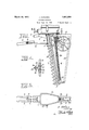
- Fig. l is a side view of the ditching' mechanism, some parts being shown in section.
- Fig. 2 is a front view, seen from the tractor side.
- Fiel'. 3 is a sectional view through the gearing house.
- Fig'. 4 is a'sectional view on line IVe-IV of Fig. 1, and
- Fig. 5 is a top-plan-view of Fi g. 1.
- the supporting frame of the ditching; apparatus consists of the support 1,*fto the side of which support, which is connected to the y tractor, are secured twobeams 2, which nearA theirfront ends are connected by a cross plate 3 serving as fastening for a stay 4 which at 5 is connected to the bearing sleeve 6 of the ditching screw 7.
- Thelower end of the screw 7 is journalled in a shoe 31 ⁇ secured to ⁇ or formed integral with an arm 32 which extends downwardly from the support 1.
- the sleeve 6 andthe arm 32 are preferably formed integral with'the support 1.
- the wheel frame 8 is kprovided with two vertical disposed arms 9, 9 which by means of Vsprings 10 carry a cross member ⁇ 11.
- To the framer 8 is by means of screws 34 secured a ⁇ slide 35 which is slidably mounted on a guide 36 formed-on the rear side' edge of the arm 32.k
- V'lhroughthe nut 3S is screwed a screw 14 the upper end of which is journalled in a gearing casing 15 and the lower end in a bearing 39 on the arnij32.
- the slide 35 is provided with aibore through which the screw Yhas i l Y .7o
- the cross member 11 carries the supporting frame by means of the nutl 38,-and whenthe screw-14 is turned in the one o'r the #other direction the supporting frame, and thereby the screw 7, will be raised or lowered.
- Y 15 designates the gearing casing.
- the driving force is applied from the tractor through the coupling member 16, the shaft 17 and the pinion 18 which meshes with the gear 19, which latter meshes with two gears 21 and 22 j running freely on the shaft 23 and rotating in opposite directions.
- the said gearsare provided with coupling crowns which mesh with corresponding coupling kcrowns 24, 25 on a coupling membery which has splined connection withthe shaft 23, but can be moved longitudinally of the same by means of a couplingv arm 26 which may be operated from the outsi de by means of a handle 27 In the middle position none of the coupling crowns 24. 25 mesh with the Lgears 21, 22 and the shaft 23 will ,remain unmoved. If the handle 27 is ymovedto the one or the other side one or the other of the coupling crowns 24, 25 will come into mesh and the shaft 23 accordingly rotate one way'or the other.
- the shaft 23 is ser cured a gear 28 which meshes with the gear 29 on the screw shaft 14, and thus the rotation of the shaft 23 will cause rotation of the screw in the one or the other direction and thereby also a raising or lowering movement of the ditching screw with its frame members.
- the shaft is provided with a square pin 30 or the like, which may be turned by means of a detachable handle.
- a ditching machine comprising a. wheeled supporting frame, a supporting member yieldingly suspended from the frame, a ditching screw, a gearing for said screw, a supporting frame for said screw and gearing, and means for raising and lowering the ditching screw supporting frame with respect to said supporting member.
- a ditching machine comprising a wheeled supporting frame, a supporting member yieldingly suspended from the frame, a ditching screw, a raising screw, a gearing for the screws, a supporting frame for the screws and gearing, and a nut on said raising screw connected to the supporting member yieldingly suspended from the wheel frame.
- a ditching machine in which beams are connected to the second-named supporting frame serving for the connection of the machine to a driving tractor7 a bearing sleeve connected with the supporting frame of the ditching screw for accommodatinfy the screw, and a stay for adj ustably connecting the beams to the bearing sleeve.
Landscapes
- Engineering & Computer Science (AREA)
- Mechanical Engineering (AREA)
- Mining & Mineral Resources (AREA)
- Civil Engineering (AREA)
- General Engineering & Computer Science (AREA)
- Structural Engineering (AREA)
- Agricultural Machines (AREA)
Description
H. KARLSEN DTCHING MACHINE March 29, 1932.
Filed Sept. 27, 1929 2 Sheets-Sheet l M ,//arsen March 29, 1932. H. KARLsx-:N
DITCHING MACHINE Filed Sept. 27. 1929 2 Sheets- Sheet 2 Patented 'Mal'. 29," 1932 UNITED STATES HENRY KAELSEN, OF OSLO, NORWAY, ASSIGNOR TO AURORA HANNEBORG'OF HAUGRIM, URSKOG, YHQIll-hllD', NOIRIVAYr DITCHING MACHINE 'Application filed September 27, 1929, Serial N. 395,649, and in Norway October 8, 1928.'
The present invention relates to a ditchingmachine of the type in which the ditching member consists of a screw and the object of the invention is to provide a convenient driv ing and manuvrine device for the screw, so that the screw may be raised and lowered by machine power and also be swung sideways in ,relation to the shaft of :the carriage if the formation of the ground should make it de.- 1,0 sirable to tilt the screw in relation to the machine frame.l In order to increase the elasticity of the machine in relation to obstructions which mav occur the ditching` mechanism with its driving and gearing mechanism is also resiliently suspended from arms on the carriage shaft. In order that thefr'ame-worl; shall not prevent lateral swinging 'of the ditching mechanism, the machine frame is provided with a narrow and long frame connecting' the same with the tractor, in which connection frame is secured a reinforcing stay for the frame of the ditching machine.V
Itis supposed that themachine is moved forwardly b v means of atra ctor, the driving motor of which also moves the ditching screw through a suitable Vorearirnq. The' invention is illustrated by way of eX- ample on the annexed drawings in which Fig. l is a side view of the ditching' mechanism, some parts being shown in section.
Fig. 2 is a front view, seen from the tractor side.
Fiel'. 3 is a sectional view through the gearing house.
Fig'. 4 is a'sectional view on line IVe-IV of Fig. 1, and
Fig. 5 is a top-plan-view of Fi g. 1. Y The supporting frame of the ditching; apparatus consists of the support 1,*fto the side of which support, which is connected to the y tractor, are secured twobeams 2, which nearA theirfront ends are connected by a cross plate 3 serving as fastening for a stay 4 which at 5 is connected to the bearing sleeve 6 of the ditching screw 7. Thelower end of the screw 7 is journalled in a shoe 31 `secured to `or formed integral with an arm 32 which extends downwardly from the support 1. The sleeve 6 andthe arm 32 are preferably formed integral with'the support 1. Y
The rear ends of the beams 2 eXtendbehind theframel and are secured to the upper end of a stay 33 the lower end of which is secured to the lower end of the arm 32.
The wheel frame 8 is kprovided with two vertical disposed arms 9, 9 which by means of Vsprings 10 carry a cross member `11. To the framer 8 is by means of screws 34 secured a` slide 35 which is slidably mounted on a guide 36 formed-on the rear side' edge of the arm 32.k
To the cross member 11 is by means of screws 37 "secured a nut 38,v the front side of which is'mounted slidablyon the guide 36 in the same manner as the slide 35.
V'lhroughthe nut 3S is screwed a screw 14 the upper end of which is journalled in a gearing casing 15 and the lower end in a bearing 39 on the arnij32. The slide 35 is provided with aibore through which the screw Yhas i l Y .7o
free passage. n
By this/arrangement the cross member 11 carries the supporting frame by means of the nutl 38,-and whenthe screw-14 is turned in the one o'r the #other direction the supporting frame, and thereby the screw 7, will be raised or lowered. Y 15 designates the gearing casing. The driving force is applied from the tractor through the coupling member 16, the shaft 17 and the pinion 18 which meshes with the gear 19, which latter meshes with two gears 21 and 22 j running freely on the shaft 23 and rotating in opposite directions. The said gearsare provided with coupling crowns which mesh with corresponding coupling kcrowns 24, 25 on a coupling membery which has splined connection withthe shaft 23, but can be moved longitudinally of the same by means of a couplingv arm 26 which may be operated from the outsi de by means of a handle 27 In the middle position none of the coupling crowns 24. 25 mesh with the Lgears 21, 22 and the shaft 23 will ,remain unmoved. If the handle 27 is ymovedto the one or the other side one or the other of the coupling crowns 24, 25 will come into mesh and the shaft 23 accordingly rotate one way'or the other. 0n the shaft 23 is ser cured a gear 28 which meshes with the gear 29 on the screw shaft 14, and thus the rotation of the shaft 23 will cause rotation of the screw in the one or the other direction and thereby also a raising or lowering movement of the ditching screw with its frame members. In order that the screw also may be manoeuvred without the motor being in operation, the shaft is provided with a square pin 30 or the like, which may be turned by means of a detachable handle.
Having now particularly described and ascertained the nature of my said invention and in what manner the same is to be performed I declare that what I claim is: t
1. A ditching machine comprising a. wheeled supporting frame, a supporting member yieldingly suspended from the frame, a ditching screw, a gearing for said screw, a supporting frame for said screw and gearing, and means for raising and lowering the ditching screw supporting frame with respect to said supporting member.
2. A ditching machine comprising a wheeled supporting frame, a supporting member yieldingly suspended from the frame, a ditching screw, a raising screw, a gearing for the screws, a supporting frame for the screws and gearing, and a nut on said raising screw connected to the supporting member yieldingly suspended from the wheel frame.
3. A ditching machine according to claim l, in which beams are connected to the second-named supporting frame serving for the connection of the machine to a driving tractor7 a bearing sleeve connected with the supporting frame of the ditching screw for accommodatinfy the screw, and a stay for adj ustably connecting the beams to the bearing sleeve.
In testimony whereof I aiix my signature.
HENRY KARLSEN.
Applications Claiming Priority (1)
| Application Number | Priority Date | Filing Date | Title |
|---|---|---|---|
| NO1851254X | 1928-10-08 |
Publications (1)
| Publication Number | Publication Date |
|---|---|
| US1851254A true US1851254A (en) | 1932-03-29 |
Family
ID=19910472
Family Applications (1)
| Application Number | Title | Priority Date | Filing Date |
|---|---|---|---|
| US395649A Expired - Lifetime US1851254A (en) | 1928-10-08 | 1929-09-27 | Ditching machine |
Country Status (1)
| Country | Link |
|---|---|
| US (1) | US1851254A (en) |
-
1929
- 1929-09-27 US US395649A patent/US1851254A/en not_active Expired - Lifetime
Similar Documents
| Publication | Publication Date | Title |
|---|---|---|
| US3454109A (en) | Motor grader | |
| US2548676A (en) | Rotary brush sweeper attachment for power vehicles | |
| US2408268A (en) | Adjustable push grader | |
| US1851254A (en) | Ditching machine | |
| US1428194A (en) | Btjrg | |
| US3161072A (en) | Control arrangements and mechanisms for pivotable devices | |
| US2284463A (en) | Road grader | |
| US2326197A (en) | Hydraulic reverse scraper | |
| US2213635A (en) | Scraper attachment | |
| US2468319A (en) | Posthole digger attachment | |
| US1784284A (en) | Scraper-control mechanism | |
| US2526984A (en) | Posthole digger | |
| US1868081A (en) | Post hole digger | |
| US2086430A (en) | Road-grading machine | |
| US1581404A (en) | Cotton chopper | |
| US4397358A (en) | Floating rod weeder | |
| US3072198A (en) | Drive mechanism for rod weeders | |
| US1183092A (en) | Traction binder or header. | |
| US2911736A (en) | Snow removal implement | |
| USRE21259E (en) | bloom | |
| US1368355A (en) | Rotary earthworking-machine | |
| US3136373A (en) | Tractor-drawn and driven rotary cultivator | |
| US1398382A (en) | Chain-tread tractor | |
| US1865328A (en) | Koab machine | |
| US1655044A (en) | Hoe arrangement |