US1851230A - Interlocking switch - Google Patents
Interlocking switch Download PDFInfo
- Publication number
- US1851230A US1851230A US497155A US49715530A US1851230A US 1851230 A US1851230 A US 1851230A US 497155 A US497155 A US 497155A US 49715530 A US49715530 A US 49715530A US 1851230 A US1851230 A US 1851230A
- Authority
- US
- United States
- Prior art keywords
- switch
- cover
- slide
- box
- opening
- Prior art date
- Legal status (The legal status is an assumption and is not a legal conclusion. Google has not performed a legal analysis and makes no representation as to the accuracy of the status listed.)
- Expired - Lifetime
Links
Images
Classifications
-
- H—ELECTRICITY
- H01—ELECTRIC ELEMENTS
- H01H—ELECTRIC SWITCHES; RELAYS; SELECTORS; EMERGENCY PROTECTIVE DEVICES
- H01H9/00—Details of switching devices, not covered by groups H01H1/00 - H01H7/00
- H01H9/10—Adaptation for built-in fuses
- H01H9/104—Adaptation for built-in fuses with interlocking mechanism between switch and fuse
Definitions
- My invention relates to what are commonly termed enclosed switches and particularly that type which employs a protecting fuse.
- One object is to rovide a construction of this character having hand operable means for opening and closing the circuit and a detachable fuse which is inaccessible when the circuit is closed.
- Another object is to provide in such a construction means for automatically locking the switch in the open circuit position when the fuse is exposed.
- Another object is to provide an enclosed fuse protected switch which can be operated when the main cover is open.
- Another object is to provide a construction of this character in which the switch can be locked in the open circuit position by moving the correlated parts to certain positions and then closing and sealing the cover.
- I provide a switch unit of any suitable character and a crank and handle for operating the same.
- the switch and operating crank are mounted in the box having a hinged cover and the switch is provided with a fuse plug which is removable through an opening in the cover.
- a su plemental cover is hinged to the main cover fiir preventing access to the fuse when the switch is in the closed position.
- Inside the box I provide a sliding interlock which coacts with the switch actuating member and with a member carried by or with the movable supplemental cover.
- the box is provided with a suitable spring latch adapted to be locked or sealed to the cover.
- Fig. 1 is a front view of a construction embodying my invention, the switch parts being in the open circuit position and the supplemental cover being raised to disclose the protecting fuse.
- Fig. 2 is a side view showing the switch handle in the closed circuit position and the supplemental cover shown closed.
- Fig. 3 is a transverse section looking upwardly and showing the parts in the open circuit position.
- Fig. 4 is a longitudinal sectional view and side elevation showing the interlocking parts in the open circuit position but with the supplemental cover closed.
- Fig. 5 is a similar view plemental cover raised and in the open position.
- Fig. 6 is a similar view showing the switch actuator in the closed circuit position with the sup lemental cover locked.
- Fig. is a similar view showing the switch actuator and the supplemental cover locked in the open circuit position.
- Fig. 8 is an exploded perspective view showing various parts of the construction.
- the box 10 may be of an suitable material and is preferab yprovi ed with a cover 11 hinged at 12 at s lower edge.
- a spring latch 13 is preferably provided secured to the inside of the hog and adapted to autoshowi ng the su the switch locked matically interlock ith the cover when the cover is closed.
- Su a latch is adapted to be sealed or locked fiby means of a sealing lock or padlock of any suitable type (not shown).
- the switch proper may be of any suitable type and is preferably carried by an insulating body 14 andgincludes a stationary contact 15 and a hinged blade 16.
- This body 14 is supported in the box in any suitable manner, for instance, b uprights or brackets such as 17 and 18.
- e outer end of the insulating body 14 is provided with suitable fuse plug terminals such as a center contact 19 and a screw shell 20 adapted to' receive the fuse plu 21.
- the cover of the box is provided wit an opening22 through which the outer end of the body 14 may project or through which the fuse plug 21 may be inserted.
- the operating crank 23 is suitably hinged or pivoted in bearings 23 in the box and connected to the movable switch plate member 16 by an insulating connector 24 of the usual type.
- the operating crank is provided with an external handle 25 of any suitable type.
- a supplemental cover 26 is hinged at 27 above the fuse plug opening 22. It will thus be seen that the parts are so mounted that the supplemental cover 26 normally tends to close by gravity and the main cover 11 tends to open by gravity when the latch 13 is released.
- the interlocking mechanism includes a slide 30 which is provided with longitudinal key-hole type slots 31, 32, and guided on the headed pins or studs 31 and 32 which are secured to the side of the box.
- a spring 33 is interposed between the slide 30 and the adjacent side wall of the box to hold the slide frictionally against accidental or unintended movements.
- Slide 30 is provided with flanges 30 which hold it spaced away from the wall of the box.
- the supplemental cover 26 is provided with 9. lug 34 which projects inwardly through a slot 35 in the main cover and has a pin 36 which extends into a notch 37 in the outer edge of the slide 30.
- lug 34 which projects inwardly through a slot 35 in the main cover and has a pin 36 which extends into a notch 37 in the outer edge of the slide 30.
- notch 37 The entrance to notch 37 is tapered somewhat to facilitate closure of the cover in case the slide has been somewhat displaced.
- a disc 38 mounted on one end of the crank shaft 23 has two pins or rollers 39 which project toward the adjacent wall of the box and coact with the walls of the opening or the slot 40 for guiding its movement and with the lugs 41 and 42 for limiting its movement. which embrace opposite sides of the adja cent arm of the crank shaft 23.
- a box having a cover, a latch for the cover, an insulating body in the box, switch contacts and fuse terminals carried by the body, a switch actuator carried by the box, a slide carried by the box for interlocking with the switch actuator and a fuse guard carried by the cover for actuating said slide, said slide being movable to block said guard and said actuator.
- An interlocking switch including a slide having an opening with spaced stop shoulders and a longitudinal slot, a rotatable member having a projection operable in said opening and in said slot, and being adapted to engage said shoulders, a switch actuator movable with said rotatable member, and a fuse guard adapted to actuate said slide.
- An interlocking switch including a slide having an opening with spaced stop shoulders and a longitudinal slot, a rotatable memher having a projection operable in said opening and in said slot, a switch actuator movable with said rotatable member and a movable fuse guard adapted to actuate said slide, said slide being operable independently of said guard for locking the fuse guard and the rotatable member.
- a box having headed studs secured to one side, a slide having key-hole slots for said studs, a rotatable switch actuator coacting with said slide, a fuse guard for moving said slide, a cover carrying the guard into and out of position to coact with said slide and a spring latch to hold the cover, said slide being movable to block said guard and said switch actuator when the latch is re leased.
- An enclosed switch including a box, a cover for the box having an opening for a fuse plug, a movable switch member within the box and having an external operating handle, a fuse plug socket accessible through said opening, a second cover hinged to the box cover and adapted to cover the fuse plug socket, a slide supported inside the box independently of the cover and having interlocking connection with the movable switch member and with the second cover, said slide 6.
- a box having a bin (1 cover with a latch, a movable switch mem er in the box, a handle and crank shaft for actuating the switch member, a disc mounted on the crank shaft and movable therewith and having a projecting pin, a slide guided in the box and having a slot to interlock with said pin when the switch is open and having a shoulder adapted to be blocked by the pin when the switch is closed, a fuse socket in the box, said cover having an opening for access to said socket.
- a second cover for said opening having a connection with said slide in the box to permit the second cover to move the slide and to permit the slide when moved independently of the cover to block the movement of the switch member and the second cover.
- An enclosed switch construction including a box, a movable cover for said box having an opening therein, an auxiliary cover for said opening, a movable switch member mounted in the box, a slide mounted in the box having means of connection with the operating member to permit normal operation of the switch member when the slide is in one position and to prevent closing of the switch when the slide is in all other positions, said slide and said auxiliary cover having corelated parts by means of which the auxiliary cover may move the slide so as to prevent the closing movement of the switch, said slide being movable independently of the auxiliary cover, said auxiliary cover and said slide having cooperating parts to prevent the opening of the auxiliary cover when the slide is in position to lock the switch in the open circuit position.
- An enclosed switch construction including a box, a main cover hinged to the box and having an opening therein, an auxiliary cover hinged to the main cover for closing said opening, switch mechanism mounted in the box and including an operating member, a slide carried by the box movable independently of the auxiliary cover and having interlocking engagement with the switch operating member to permit operation of the switch when the slide is in one of its positions and to prevent the closing movement of the switch when the slide is in two other positions.
- An enclosed switch construction including a box, a main cover hinged to said box, switch mechanism mounted in the box, a pivoted operating member mounted in the box, a slide mounted in the box and having an interlocking connection with said operating member, said slide being manually operable to disengage said interlocking connection, said slide having a slot opening toward the front of the box, said cover having an opening for access to the box, an auxiliary cover for said opening hinged to said main cover and having an offset crank pin inside the box for engagement with the slot in the slide when the'main cover isclosed and to permit the slide to be operated by the movement of the auxiliary cover when the switch is in the open circuit position.
- An enclosed switch construction including a box, a main cover for the box and havin g an opening therein to permit the insertion and removal of a fuse plug, a movable switch member within the box having a ivoted operating member within the box and an external operating handle connected thereto, an auxiliary cover hinged to the main cover and adapted to prevent access to the fuse plug opening, an interlocking member supported by the box and movable therein and having interlocking connection with the switch operating member and with the auxiliary cover, whereby the interlocking member, when in one position, will permit normal operation of the switch member, and when in another position, will prevent the operation of the switch operating member, said interlocking member being movable by the auxiliary cover to a position to block the closing movement of the switch, said interlocking member being movable manually and independently of the auxilary cover to a position to block the opening of the auxiliary cover and to lock the switch in the open circuit position.
- An enclosed switch construction including a box having a cover with' a fuse passage in the cover, a switch mounted in the box, a rotatable member mounted in one side of the box, an operating connection between said rotatable member and the movable switch member, a slide supported in the box having an arcuate cut-out portion, a pin carried by said rotatable member and rotatable in said arcuate cut-out portion, said slide also having a longitudinal slot adapted to receive said pin, said slide being movable manually in the box into interlocking relation with said pin, and said slide having a slot opening toward the front of the box and a shoulder adjacent thereto, an auxiliary cover hinged to the main cover having a crank pin inside the cover adapted to enter said slot and adapted to engage said shoulder, said auxiliary cover being adapted to operate the slide when the switch is in the open circuit position, when said crank pin is engaged in said slot and said slide being also adapted to block the operation of said auxiliary cover when the shoulder on the slide is interposed in the path of movement
- An enclosed switch construction including a box, a main cover hinged to the box and having an opening therein, an auxiliary cover hinged to the main cover for closin said opening, switch mechanism mounted 1n the box and including an operating member, a slide carried by the box movable independently of the auxiliary cover and having interlocking engagement with the switch operating member to permit operation of the switch when the slide is in one of its positions and to prevent the closing movement of the switch when the slide is in two other positions, said slide having a slot openin toward the front of the box and having a s oulder extending transversely tothe direction of longitudinal movement of the slide, said auxiliary cover having a lug projecting inside the main cover with a pro ection adapted when in one position to en age said shoulder and prevent opening 0 the auxiliary cover when the switch is in the closed circuit position, said projection being adapted to enter the open slot when the slide is in a osition to permit operation of the switch, said auxiliar cover being adapted to actuate the slide w en the
Landscapes
- Switch Cases, Indication, And Locking (AREA)
Description
March 29, 1932. YOUNG 1,851,230
INTERLOCKING SWITCH Filed Nov. 21, 1930 .3 Sheets-Sheet 1 March 29, 1932. F. A. YOUNG 1,851,230
INTERLOCKING SWITCH Filed Nov. 21, 1930 3 Sheets-Sheet 2 March 29, 1932. F. A. YOUNG INTERLOCKING SWITCH Filed Nov- 2.1. 1930 3 Sheets-Sheet 3 'INVENTOR Frank A. Youn i ATTO EY Patented Mar. 29, 1932 UNITED STATES PATENT OFFICE FRANK A. YOUNG, OF MERIDEN, CONNECTICUT, ASSIGNOR TO THE TRUMBULL ELEC- TRIC MANUFACTUBIN G COMPANY, OF CONNECTICUT OI PLAINVILLE, CONNECTICUT, A CORPORATION IIINTERLOCKING SWITCH Application filed November 21, 1830. Serial No. 483,155.
My invention relates to what are commonly termed enclosed switches and particularly that type which employs a protecting fuse.
One object is to rovide a construction of this character having hand operable means for opening and closing the circuit and a detachable fuse which is inaccessible when the circuit is closed.
Another object is to provide in such a construction means for automatically locking the switch in the open circuit position when the fuse is exposed.
Another object is to provide an enclosed fuse protected switch which can be operated when the main cover is open.
Another object is to provide a construction of this character in which the switch can be locked in the open circuit position by moving the correlated parts to certain positions and then closing and sealing the cover.
In carrying out the invention I provide a switch unit of any suitable character and a crank and handle for operating the same. The switch and operating crank are mounted in the box having a hinged cover and the switch is provided with a fuse plug which is removable through an opening in the cover. A su plemental cover is hinged to the main cover fiir preventing access to the fuse when the switch is in the closed position. Inside the box I provide a sliding interlock which coacts with the switch actuating member and with a member carried by or with the movable supplemental cover. The box is provided with a suitable spring latch adapted to be locked or sealed to the cover.
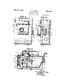
Fig. 1 is a front view of a construction embodying my invention, the switch parts being in the open circuit position and the supplemental cover being raised to disclose the protecting fuse.
Fig. 2 is a side view showing the switch handle in the closed circuit position and the supplemental cover shown closed.
Fig. 3 is a transverse section looking upwardly and showing the parts in the open circuit position.
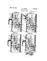
Fig. 4 is a longitudinal sectional view and side elevation showing the interlocking parts in the open circuit position but with the supplemental cover closed.
Fig. 5 is a similar view plemental cover raised and in the open position.
Fig. 6 is a similar view showing the switch actuator in the closed circuit position with the sup lemental cover locked.
Fig. is a similar view showing the switch actuator and the supplemental cover locked in the open circuit position.
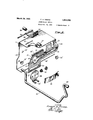
Fig. 8 is an exploded perspective view showing various parts of the construction.
The box 10 may be of an suitable material and is preferab yprovi ed with a cover 11 hinged at 12 at s lower edge. A spring latch 13 is preferably provided secured to the inside of the hog and adapted to autoshowi ng the su the switch locked matically interlock ith the cover when the cover is closed. Su a latch is adapted to be sealed or locked fiby means of a sealing lock or padlock of any suitable type (not shown).
The switch proper may be of any suitable type and is preferably carried by an insulating body 14 andgincludes a stationary contact 15 and a hinged blade 16. This body 14 is supported in the box in any suitable manner, for instance, b uprights or brackets such as 17 and 18. e outer end of the insulating body 14 is provided with suitable fuse plug terminals such as a center contact 19 and a screw shell 20 adapted to' receive the fuse plu 21. The cover of the box is provided wit an opening22 through which the outer end of the body 14 may project or through which the fuse plug 21 may be inserted. f
The operating crank 23 is suitably hinged or pivoted in bearings 23 in the box and connected to the movable switch plate member 16 by an insulating connector 24 of the usual type. The operating crank is provided with an external handle 25 of any suitable type.
A supplemental cover 26 is hinged at 27 above the fuse plug opening 22. It will thus be seen that the parts are so mounted that the supplemental cover 26 normally tends to close by gravity and the main cover 11 tends to open by gravity when the latch 13 is released.
The interlocking mechanism includes a slide 30 which is provided with longitudinal key- hole type slots 31, 32, and guided on the headed pins or studs 31 and 32 which are secured to the side of the box.
A spring 33 is interposed between the slide 30 and the adjacent side wall of the box to hold the slide frictionally against accidental or unintended movements.
The supplemental cover 26 is provided with 9. lug 34 which projects inwardly through a slot 35 in the main cover and has a pin 36 which extends into a notch 37 in the outer edge of the slide 30. When the supplemental cover is raised to the position shown in Fig. 1 and Fig. 5 the pin 36 pressing against the lower edge of the notch 37 forces the slide 30 downwardly. When the supplemental cover is lowered it raises the slide 30 as will be obvious from inspection in Fig. 5.
The entrance to notch 37 is tapered somewhat to facilitate closure of the cover in case the slide has been somewhat displaced.
A disc 38 mounted on one end of the crank shaft 23 has two pins or rollers 39 which project toward the adjacent wall of the box and coact with the walls of the opening or the slot 40 for guiding its movement and with the lugs 41 and 42 for limiting its movement. which embrace opposite sides of the adja cent arm of the crank shaft 23.
The interlocking of the pins 39 with the walls of the extension slot 40' when the parts are inthe position shown in Fig. 5, locks the switch in the open circuit posit-ion.
When the parts are in the position shown in Fig. 6 it will be seen that there IS nothing to prevent the operation of the switch actuator but that the supplemental cover 26 can not be raised because the slide 30 is blocked by the engagement of the shoulder 39 with the pin 39.
When the slide 30 is moved downwardly to the posit-ion of Figs. 5 and 7 it is stopped in a suitable manner for instance by the upper end of the slot extension 40 meeting the upper pin 39 on the disc 38.
By opening the cover 11 and moving the slide 30 to the position shown in Fig. 7 while the switch is in the open circuit position and then closing the supplemental cover 26 and sealing or locking the latch 13, the parts of the switch will be held in the open circuit position and the fuse plug will be also locked or protected against removal or tampering because the pin 36 engages shoulder 43 so that cover'26 can not be operated.
It will be seen that the construction is sim- This disc has two prongs 38' ple, inexpensive and yet substantialfpractical and durable. Although the switch is shown of the hand-operated type it should be understood that similar improvements may be embodied in switches of the Snap action or quick break type.
While I have shown the construction applied to a switch provided with means for receiving a fuse of the plug type, it will be obvious that it can be arranged to receive fuses of any other suitable type.
I claim:
1. In an interlocking switch, a box having a cover, a latch for the cover, an insulating body in the box, switch contacts and fuse terminals carried by the body, a switch actuator carried by the box, a slide carried by the box for interlocking with the switch actuator and a fuse guard carried by the cover for actuating said slide, said slide being movable to block said guard and said actuator.
2. An interlocking switch including a slide having an opening with spaced stop shoulders and a longitudinal slot, a rotatable member having a projection operable in said opening and in said slot, and being adapted to engage said shoulders, a switch actuator movable with said rotatable member, and a fuse guard adapted to actuate said slide.
3. An interlocking switch including a slide having an opening with spaced stop shoulders and a longitudinal slot, a rotatable memher having a projection operable in said opening and in said slot, a switch actuator movable with said rotatable member and a movable fuse guard adapted to actuate said slide, said slide being operable independently of said guard for locking the fuse guard and the rotatable member.
4. In a switch, a box having headed studs secured to one side, a slide having key-hole slots for said studs, a rotatable switch actuator coacting with said slide, a fuse guard for moving said slide, a cover carrying the guard into and out of position to coact with said slide and a spring latch to hold the cover, said slide being movable to block said guard and said switch actuator when the latch is re leased. i
5. An enclosed switch including a box, a cover for the box having an opening for a fuse plug, a movable switch member within the box and having an external operating handle, a fuse plug socket accessible through said opening, a second cover hinged to the box cover and adapted to cover the fuse plug socket, a slide supported inside the box independently of the cover and having interlocking connection with the movable switch member and with the second cover, said slide 6. In a switch, a box having a bin (1 cover with a latch, a movable switch mem er in the box, a handle and crank shaft for actuating the switch member, a disc mounted on the crank shaft and movable therewith and having a projecting pin, a slide guided in the box and having a slot to interlock with said pin when the switch is open and having a shoulder adapted to be blocked by the pin when the switch is closed, a fuse socket in the box, said cover having an opening for access to said socket. a second cover for said opening having a connection with said slide in the box to permit the second cover to move the slide and to permit the slide when moved independently of the cover to block the movement of the switch member and the second cover.
7. An enclosed switch construction including a box, a movable cover for said box having an opening therein, an auxiliary cover for said opening, a movable switch member mounted in the box, a slide mounted in the box having means of connection with the operating member to permit normal operation of the switch member when the slide is in one position and to prevent closing of the switch when the slide is in all other positions, said slide and said auxiliary cover having corelated parts by means of which the auxiliary cover may move the slide so as to prevent the closing movement of the switch, said slide being movable independently of the auxiliary cover, said auxiliary cover and said slide having cooperating parts to prevent the opening of the auxiliary cover when the slide is in position to lock the switch in the open circuit position.
8. An enclosed switch construction including a box, a main cover hinged to the box and having an opening therein, an auxiliary cover hinged to the main cover for closing said opening, switch mechanism mounted in the box and including an operating member, a slide carried by the box movable independently of the auxiliary cover and having interlocking engagement with the switch operating member to permit operation of the switch when the slide is in one of its positions and to prevent the closing movement of the switch when the slide is in two other positions.
9. An enclosed switch construction including a box, a main cover hinged to said box, switch mechanism mounted in the box, a pivoted operating member mounted in the box, a slide mounted in the box and having an interlocking connection with said operating member, said slide being manually operable to disengage said interlocking connection, said slide having a slot opening toward the front of the box, said cover having an opening for access to the box, an auxiliary cover for said opening hinged to said main cover and having an offset crank pin inside the box for engagement with the slot in the slide when the'main cover isclosed and to permit the slide to be operated by the movement of the auxiliary cover when the switch is in the open circuit position.
10. An enclosed switch construction including a box, a main cover for the box and havin g an opening therein to permit the insertion and removal of a fuse plug, a movable switch member within the box having a ivoted operating member within the box and an external operating handle connected thereto, an auxiliary cover hinged to the main cover and adapted to prevent access to the fuse plug opening, an interlocking member supported by the box and movable therein and having interlocking connection with the switch operating member and with the auxiliary cover, whereby the interlocking member, when in one position, will permit normal operation of the switch member, and when in another position, will prevent the operation of the switch operating member, said interlocking member being movable by the auxiliary cover to a position to block the closing movement of the switch, said interlocking member being movable manually and independently of the auxilary cover to a position to block the opening of the auxiliary cover and to lock the switch in the open circuit position.
11. An enclosed switch construction including a box having a cover with' a fuse passage in the cover, a switch mounted in the box, a rotatable member mounted in one side of the box, an operating connection between said rotatable member and the movable switch member, a slide supported in the box having an arcuate cut-out portion, a pin carried by said rotatable member and rotatable in said arcuate cut-out portion, said slide also having a longitudinal slot adapted to receive said pin, said slide being movable manually in the box into interlocking relation with said pin, and said slide having a slot opening toward the front of the box and a shoulder adjacent thereto, an auxiliary cover hinged to the main cover having a crank pin inside the cover adapted to enter said slot and adapted to engage said shoulder, said auxiliary cover being adapted to operate the slide when the switch is in the open circuit position, when said crank pin is engaged in said slot and said slide being also adapted to block the operation of said auxiliary cover when the shoulder on the slide is interposed in the path of movement of the crank pin.
12. An enclosed switch construction including a box, a main cover hinged to the box and having an opening therein, an auxiliary cover hinged to the main cover for closin said opening, switch mechanism mounted 1n the box and including an operating member, a slide carried by the box movable independently of the auxiliary cover and having interlocking engagement with the switch operating member to permit operation of the switch when the slide is in one of its positions and to prevent the closing movement of the switch when the slide is in two other positions, said slide having a slot openin toward the front of the box and having a s oulder extending transversely tothe direction of longitudinal movement of the slide, said auxiliary cover having a lug projecting inside the main cover with a pro ection adapted when in one position to en age said shoulder and prevent opening 0 the auxiliary cover when the switch is in the closed circuit position, said projection being adapted to enter the open slot when the slide is in a osition to permit operation of the switch, said auxiliar cover being adapted to actuate the slide w en the switch is in the open circuit position, said switch operating member bein adapted to prevent the o eration of the slide when the switch is in t e closed circuit position, said slide being manually operable to lock the switch in the open circuit position independently of the position of the auxiliary cover.
FRANK A. YOUNG.
Priority Applications (1)
| Application Number | Priority Date | Filing Date | Title |
|---|---|---|---|
| US497155A US1851230A (en) | 1930-11-21 | 1930-11-21 | Interlocking switch |
Applications Claiming Priority (1)
| Application Number | Priority Date | Filing Date | Title |
|---|---|---|---|
| US497155A US1851230A (en) | 1930-11-21 | 1930-11-21 | Interlocking switch |
Publications (1)
| Publication Number | Publication Date |
|---|---|
| US1851230A true US1851230A (en) | 1932-03-29 |
Family
ID=23975685
Family Applications (1)
| Application Number | Title | Priority Date | Filing Date |
|---|---|---|---|
| US497155A Expired - Lifetime US1851230A (en) | 1930-11-21 | 1930-11-21 | Interlocking switch |
Country Status (1)
| Country | Link |
|---|---|
| US (1) | US1851230A (en) |
Cited By (1)
| Publication number | Priority date | Publication date | Assignee | Title |
|---|---|---|---|---|
| US4982310A (en) * | 1987-10-30 | 1991-01-01 | Cooper Power Systems, Inc. | Switchgear enclosure with improved electronic control access door and lock |
-
1930
- 1930-11-21 US US497155A patent/US1851230A/en not_active Expired - Lifetime
Cited By (1)
| Publication number | Priority date | Publication date | Assignee | Title |
|---|---|---|---|---|
| US4982310A (en) * | 1987-10-30 | 1991-01-01 | Cooper Power Systems, Inc. | Switchgear enclosure with improved electronic control access door and lock |
Similar Documents
| Publication | Publication Date | Title |
|---|---|---|
| US2983799A (en) | Switching apparatus with lock-off device | |
| US2512505A (en) | Operating means for enclosed switches | |
| US2260073A (en) | Enclosed circuit breaker | |
| US4074091A (en) | Interlocking operating mechanism for enclosed switchgear having defeater interlock | |
| US2263760A (en) | Enclosed circuit breaker | |
| US3122615A (en) | Interlock mechanism for enclosed switching apparatus | |
| US2163230A (en) | Front operated switch | |
| US1851230A (en) | Interlocking switch | |
| US2907840A (en) | Front operated enclosed switching apparatus | |
| GB1135169A (en) | Metal enclosed switchgear | |
| US3028459A (en) | Switch and enclosure therefor | |
| US2344636A (en) | Enclosed electric safety switch | |
| US4104491A (en) | Latch means for switch enclosure | |
| US2506148A (en) | Safety switch | |
| US1983902A (en) | Safety switch | |
| US2332633A (en) | Enclosed switch | |
| US3295025A (en) | Movable barrier serving as shutter means and enclosure door in switchgear housing | |
| US2191523A (en) | Enclosed circuit breaker | |
| US2917593A (en) | Enclosed circuit breaker | |
| US2916904A (en) | Locking means for casing enclosed mechanisms | |
| US2215299A (en) | Electric switch enclosure | |
| US1652795A (en) | X i inclosed switch | |
| US2218028A (en) | Enclosed switch | |
| US2954444A (en) | Interlock mechanism for an enclosed electric switch | |
| US3348003A (en) | Switch housing including improved defeatable cover latch means |