US1851175A - System of broadcasting - Google Patents
System of broadcasting Download PDFInfo
- Publication number
- US1851175A US1851175A US233801A US23380127A US1851175A US 1851175 A US1851175 A US 1851175A US 233801 A US233801 A US 233801A US 23380127 A US23380127 A US 23380127A US 1851175 A US1851175 A US 1851175A
- Authority
- US
- United States
- Prior art keywords
- frequency
- oscillations
- modulated
- supersonic
- audio
- Prior art date
- Legal status (The legal status is an assumption and is not a legal conclusion. Google has not performed a legal analysis and makes no representation as to the accuracy of the status listed.)
- Expired - Lifetime
Links
- 230000010355 oscillation Effects 0.000 description 88
- 230000005540 biological transmission Effects 0.000 description 9
- 238000000034 method Methods 0.000 description 9
- 238000004891 communication Methods 0.000 description 2
- ATJFFYVFTNAWJD-UHFFFAOYSA-N Tin Chemical compound [Sn] ATJFFYVFTNAWJD-UHFFFAOYSA-N 0.000 description 1
- 240000008042 Zea mays Species 0.000 description 1
- 230000003321 amplification Effects 0.000 description 1
- 238000010276 construction Methods 0.000 description 1
- 230000002452 interceptive effect Effects 0.000 description 1
- 238000012423 maintenance Methods 0.000 description 1
- 238000003199 nucleic acid amplification method Methods 0.000 description 1
- 230000003534 oscillatory effect Effects 0.000 description 1
Images

Classifications
-
- H—ELECTRICITY
- H04—ELECTRIC COMMUNICATION TECHNIQUE
- H04B—TRANSMISSION
- H04B14/00—Transmission systems not characterised by the medium used for transmission
- H04B14/08—Transmission systems not characterised by the medium used for transmission characterised by the use of a sub-carrier
Definitions
- This invention relates to ⁇ the transmie'sion of intelligence 'by ⁇ radiant' energy and more i provide animproved Syste'in fortaismitting enrgycempri'sng sendingsystemrrangecl i Carrier' Wafes'er1seillatioils,preferablyA4 of a; high supervznidible frequency"-modnlated:
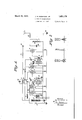
- the device l'OL'is f thnsnagl fconstru'etimi including ,a plate 12 uponyvhichy the feletrons'I irripiige, and a grid i3' fr lcontrolling the flow of electrons.
- the battery 7 is provided in the grid circuit of said device, the effective potential of which with respect to the grid is adapted to be varied by means of the secondary of the transformer 8 in accordance With the audio frequency signals.
- the plate 12 of the device 34 is adapted to be supplied through the audio frequency choke coil 9, by the high potential source 27.y
- the intermediate modulator 35 vof the usual construction, is adapted to .be supplied with filament current by the A battery 21.
- the input of the device is supplied through the coil 24 and the high potential source 2T supplies the plate 12 through the audio frequency.
- inductance 31 Inductively coupled to the inductance 30 is inductance 31 shunted by the condenser y33 and included in the plate circuit of the rtherniiouic modulated radio frequency amplifier 36. Also included in the plate circuit of said device is the inductance 37.
- the output of the amplifier 36 is adapted to be supplied to the circuit comprising the condenser 38 and the inductance 39 shunted by the condenser 4 0.;
- the antenna 41 is supplied through the inductance 42 and completes its circuit, to the ground 44, through the variable tap 43 on the inductance 39, the position of which tap mal; be varied to obtain proper resonance.
- the input 8 of the audio modulator tube 34 serves to impress upon the grid of said tube the audio frequency with which it is desired to modulate the intermediate frequency.
- the output of the modulator tube 34 is connected to the source of high potential 27 through the usual audio frequency ychoke 9.
- the intermediate modulator tube 35 thus has impressed upon its plate a potential varied in accordance with the audio frequency signals and therefore serves to amplify the intermediate frequency oscillation, m a manner'which is'modulated in accordance with the audio frequency signals;
- Ineluded in the plate circuit of the intermediatemodulator tube 35 is an intermediate frequency choke composed of inductance 30 and condenser 3 2.
- this intermediate frequency choke Inductively coupled to this intermediate frequency choke is a similar intermediate frequency choke, composed of inductance 31 and condenser 33, and included in ⁇ fthe plate circuit of ⁇ the modulated frequency amplifier 36 so'as to vary the potential 'impressed upon the plate of said amplifier 'tube and thus vary the total amount of transmission. Consequently the output of the tube 36 is modulated at intermediate frequencies only since there is no audio frequency voltage component impressed upon the plate circuit of this tube and it, therefore, by
- frequency of the generator 20 is 40,000 cycles per second
- land that the voice currents include a frequency range of from 200 to 2000 cycles per second
- the frequency of the generator 10 is 1,000,000 cycles there will be produced in the output circuit a series of oscillations of a frequency of 1,000,000 and also two side bands one comprising frequencies of from 958,000 to 962,000 cycles per second and the 4other of from 1,038,000 to 1,042,000.
- This figure shows the relationship of these frequencies to each other, C indicating the carrier frequency, B and B1 the upper and lower side band stations and A and A1 the audio frequency side band components.
- the first method by receiving the carrier frequency C detecting and obtaining therefrom either sideband B or B1 then detecting the sideband and obtaining the audio frequency components A, and the second method simply by tuning an ordinary receiver to the sideband B or B1 and detecting and obtaining the audio frequency A.
- a receiver such as is shown in Fig. 3 is utilized.
- a receiving element is positioned so as to intercept the Waves transmitted from cuit 62, comprising an inductance 63 and a '5' variable condenser 64.
- the closed oscillatory circuit 62 is connected to the input circuit of the three electrode thermionic detec- *"7 being controlled by a variable rheostat 71.
- a-piiflf'elmi..and. l@ 'said A'circuit includes f iiithctfransmtteby,the,oscillator QOQliel '.Qiitput circui'itrnsmtsfthese detected 'pr ifctifie'd oscillations through the vinductance ZQiWhich isadjustaby coupled with theniu- 11d Dg ytheciufvedpocionm?itschfacterisizic curye 75y th .intermediate frequency'produced 870V,
- the tuning v being suitably adjusted to the frequency of one of the side stations B or B produced by the modulation of the output of the oscillator l0 by the lower supersonic frequency.
- the grid condenser 97 included in the grid circuit of the thermionic device 96 permits a negative potential to be built up upon the grid of said device so as to cause the device to be operated on the curved portion of its characteristic curve in the usual manner and thus to act to rectify or otherwise detect the oscillations, set up in the tuned circuit.
- therinionic device 96 including the indicating device 83 superimposed currents correspondingr in frequency to one of the side stations produced by the modulation of the carrier frequency by the lower supersonic frequency at the sending station andvarying in amplitude according to the signal currents impressed on said lower supersonic oscillation by the input through transformer 8.
- the by-pass condenser 84 y ⁇ permits the flow of these superimposed currents and the unidirectional currents corresponding to the envelope thereof affects the indicating device S3 causing it to produce Sound Waves of the saine character as the audio frequency at the transmitter.
- the indicatingT device 83 of course, may be a l telephone receiver.
- the receiving station such as is shown in Fig. 3, however, obtains'a de luxe broadcasting service which remains practically unresponsive to the energy emitted by broadcasting stations other than the y one intended to hear.
- the fretively one of these series of waves being emitted from the sending station of the form shown diagrammatically in Fig. l, the ref DC receiving station will be selectively responsive only to the sending station of the type disclosed herein and will remain inert to the yenergy emitted from the other Sending station. rIn this manner the receiving station may readily'listen in upon a concert or lecture of a relatively distant station if desired,
- the method of radio transmission comprising generating high frequency oscillations, generating lower supersonic frequency oscillations, modulating said lower supersonic frequency oscillations b an audio frequency, modulating the high requency oscillations by such modulated lower supersonic frequency oscillations, preventing modulation of said high frequency oscillations by an audio frequency component, transmitting said modulated high frequency oscillations, receiving and detectin said high frequency oscillations and there y reproducing said lower' supersonic frequency oscillations detecting the latter named oscillations and obtaining tlierebysaid audio frequency, independently receiving the side station roduced by the modulation of the high requency oscillations by said lower frequency oscillations, and detecting said side station, and producing thereby said audio frequency.
- the method of radio frequency transmission comprising generating high frequency oscillations, generating lower supersonic frequency'oscillations, modulatin said lower supersonic frequency oscillationsy an audio frequency, modulating the hi h frequency oscillations by said modulate lower supersonic frequency oscillations, preventing modulationy of said .high frequency oscillations by an audio frequency component, transf mitting said modulated high frequency oscillations, receiving the side station; produced by the modulation of the high frequency oscillations by said lower frequency oscillations, and detecting said side station and reproducing thereby said audio frequency.
- vThemetliod of radio transmission comprising fmodulating a loWy supersonic 'frequency series'of oscillations by ,an audio frer quency, modulating a vhighfrequency seriesk of oscillations by said modulated low superu sonic frequency series fof :oscillationsy While preventing demodulation of the modulated jy low' supersonic frequency oscillations thereby preventing modulation of said high frequency series of oscillations by an audio frequency lcomponent existing insaidqmodulated low supersonic frequency series of oscillations,
- nication comprising modulating a low super Vsonic frequency series of oscillations by anl audio frequency, modulatingA a high fre-VV i quentv series of oscillations by said 'modulated low frequency oscillations,'preventing vr ,modulation of saidliigh frequencyV oscilla-y tions by an audioV frequency component,v transmittiiigsaid modulated high frequency oscillations, receiving andV detecting the side station".
- a radio' communication system comprising- Vinga vgenerator of high frequency'oscillaL Vtions,-infieansifor amplifying said high ⁇ fre-k quency oscillations, means Yfortraiismitting said amplified high frequencyoscillations, a
- a radio communication system comrising a generator of high frequency oscilations, a generator of lower supersonic frequency oscillations, means for modulating said lower supersonic frequency oscillations in accordance with an audio frequency signal, an amplifier circuit comprising an electron discharge device having an input circuit 2 and an output circuit, means for impressing said high frequency oscillations upon said input circuit, means for impressing said modulated supersonic frequency oscillations upon said output circuit for varying the characteristics thereof in accordance with said modulated supersonic oscillations whereby said high frequency oscillations are modulated by said mo ulated lower supersonic fre uency oscillations without demodulation o said 0 modulated supersonic frequency oscillations.
- means for generating high requency oscillations means for generating intermediate frequency oscillations, a source of audio frequency energy, means for modulating said intermediate frequency oscillations by said audio frequency energy, means for modulating said hi h frequency oscillations by said modulate intermediate frequency oscillations, said lastnamed means comprising an electron dis- ⁇ char device arranged so .as to act as an n mp ifer for said high frequency oscillay K tions, the amplification factor of said ampli- 5 bomb being controlled in accordance with said modulated intermediate frequency by means 1n the output circuit of said amplifier for impressing said modulated intermediate frequency energy upon said output circuit where- 53 y said high frequency energy is modulated by said modulated intermediate frequency vwithout demodulation ofsaid modulated intermediate frequency energy.
Landscapes
- Engineering & Computer Science (AREA)
- Computer Networks & Wireless Communication (AREA)
- Signal Processing (AREA)
- Transmitters (AREA)
Description
J. HY HAMMOND, JR
SYSTEM oF BROADCASTING March 29, 1932.
Filed NOV. 17, 1927 mmm mmm
Q. Wiz: illllllllllllllllill-AIL#I Sheets-Sheet l INVENTOR JOHN HAYS HAMMOND JR.
my@ ,Mada
TTORNEY March 29, 1932.
.1. H. HAMMOND, JR 1,851,175
SYSTEM OF BROADCASTING Filed Nov. 17. 1927 2 Sheets-Sheet 2 v llll =lllllllll NVENTOR JOHN HAYS HMMOND JR.
TTORNEY Patented' Magfza; 1932 f JH mais GLOUCESTR, e-
This invention relates to` the transmie'sion of intelligence 'by `radiant' energy and more i provide animproved Syste'in fortaismitting enrgycempri'sng sendingsystemrrangecl i Carrier' Wafes'er1seillatioils,preferablyA4 of a; high supervznidible frequency"-modnlated:
` '.Oneobject 'of' this inventie'n' is te pro'vicle a s'jfetm Gfbroadcting in which twe clesses "et service mayberendered, one intl-ndertforv `the "genera-l, type Of ,receiving Sttin over Whieh thererfis no .Supervision eceit that givlenf ly the eperiitor'n'd I tlie'jOt-her la', Service of relatively better qimlit'yfin W'hielrthe Service and maintenance' in y'lbe supervised;l
by'aQsei'ies, bfiWave'so'zlower ibut 'super- Aaudible reql'ieney thelatter- Seriee f Weves being ino'llet'eid by "desired signlsrsueli fr exemple Yoicewevfe's'; and toprdvide an rrngeinent for' 'the VLselective. reception of 1 veither Or beth of'said n'i'odiilatedtosveillations f andthe trnsformation of theenergy thereof intof sensible 'manifestitiois.v L
-pearffromthe following `deseription teken 1n connection With the 'acc01'np'anying'-drtwings inwhiehrf Y Y ing' station' conetruetediniaecbrclnee-vith isliin of the emitteclfrequencyComponents;,
arrangedV to ing a carrier weyegrlfie'.SoiireShowiiiiiftliisr instance includjeisgtlie .three electrode ficher Wve oseilljator.'V The device l'OL'is f thnsnagl fconstru'etimi including ,a plate 12 uponyvhichy the feletrons'I irripiige, and a grid i3' fr lcontrolling the flow of electrons. Thesetparts fire connected inthe;itrrelatedinutiiely 55 V'c-oiiplediruits; olnprisin'g e transferinei' having .Wmdingsil ,lgand i6 'which refcdl'ir nefcted Tin the plate, Agrid,andoutpilt Circuits of relatively ighfrequeiiey; nf eiifnstaince 'a For :producing :.oscillti'onf l A in'fthe plate; grid yand Aoutputei;1'-c1iits resp' f tively:Y y'IAhe'pla-te 12 isnfaintainedriat; a positire potential Kwith respect `to .th;,filiinent by r '29 t6 the plate?. .Thie-regeneratiifelcreuitis thev cpaty of whih maybeafdjnstd sc that Y, 'oscillations' -of zu;predetermineclA ffrquency, 90 Y the.fiiment'1Ladaptedtebe;sumelietljyfthe` 95 -r former 8 with the audio frequency or signal current. The battery 7 is provided in the grid circuit of said device, the effective potential of which with respect to the grid is adapted to be varied by means of the secondary of the transformer 8 in accordance With the audio frequency signals. The plate 12 of the device 34 is adapted to be supplied through the audio frequency choke coil 9, by the high potential source 27.y
The intermediate modulator 35, vof the usual construction, is adapted to .be supplied with filament current by the A battery 21. The input of the device is supplied through the coil 24 and the high potential source 2T supplies the plate 12 through the audio frequency. choke 9, rpreviously mentioned, and the radio frequency coil 30shunted by the condenser 32.
Inductively coupled to the inductance 30 is inductance 31 shunted by the condenser y33 and included in the plate circuit of the rtherniiouic modulated radio frequency amplifier 36. Also included in the plate circuit of said device is the inductance 37. The output of the amplifier 36 is adapted to be supplied to the circuit comprising the condenser 38 and the inductance 39 shunted by the condenser 4 0.; The antenna 41 is supplied through the inductance 42 and completes its circuit, to the ground 44, through the variable tap 43 on the inductance 39, the position of which tap mal; be varied to obtain proper resonance.
f aving now described the transmitter of my invention I will briefly describe its operation. The input 8 of the audio modulator tube 34 serves to impress upon the grid of said tube the audio frequency with which it is desired to modulate the intermediate frequency. The output of the modulator tube 34 is connected to the source of high potential 27 through the usual audio frequency ychoke 9. The intermediate modulator tube 35 thus has impressed upon its plate a potential varied in accordance with the audio frequency signals and therefore serves to amplify the intermediate frequency oscillation, m a manner'which is'modulated in accordance with the audio frequency signals; Ineluded in the plate circuit of the intermediatemodulator tube 35 is an intermediate frequency choke composed of inductance 30 and condenser 3 2. Inductively coupled to this intermediate frequency choke is a similar intermediate frequency choke, composed of inductance 31 and condenser 33, and included in `fthe plate circuit of` the modulated frequency amplifier 36 so'as to vary the potential 'impressed upon the plate of said amplifier 'tube and thus vary the total amount of transmission. Consequently the output of the tube 36 is modulated at intermediate frequencies only since there is no audio frequency voltage component impressed upon the plate circuit of this tube and it, therefore, by
frequency of the generator 20 is 40,000 cycles per second, land that the voice currents include a frequency range of from 200 to 2000 cycles per second, there will be produced in the output circuit of the modulator a series of oscillations having a frequency of 40,000 cycles per second and also of two side bands, comprising a lower band containing a plurality of series of oscillations varying in frequency from 38,000 to 39,800 cycles inclusive and an upper band containing a plurality of series of oscillations varying from 40,200 to 42,000 cycles per second inclusive. Then assuming that the frequency of the generator 10 is 1,000,000 cycles there will be produced in the output circuit a series of oscillations of a frequency of 1,000,000 and also two side bands one comprising frequencies of from 958,000 to 962,000 cycles per second and the 4other of from 1,038,000 to 1,042,000. This figure shows the relationship of these frequencies to each other, C indicating the carrier frequency, B and B1 the upper and lower side band stations and A and A1 the audio frequency side band components.
It will be'obvious from the above and from the description of the transmitter that it would be possible to receive the transmission by either of two separate and distinct methods. The first method by receiving the carrier frequency C detecting and obtaining therefrom either sideband B or B1 then detecting the sideband and obtaining the audio frequency components A, and the second method simply by tuning an ordinary receiver to the sideband B or B1 and detecting and obtaining the audio frequency A.
For using the first method of transmission, a receiver such as is shown in Fig. 3 is utilized. A receiving element is positioned so as to intercept the Waves transmitted from cuit 62, comprising an inductance 63 and a '5' variable condenser 64.
For detecting the energy received by the open aerial circuit 60. 61, the closed oscillatory circuit 62. is connected to the input circuit of the three electrode thermionic detec- *"7 being controlled by a variable rheostat 71. i
, a-piiflf'elmi..and. l@ 'said A'circuit includes f iiithctfransmtteby,the,oscillator QOQliel '.Qiitput circui'itrnsmtsfthese detected 'pr ifctifie'd oscillations through the vinductance ZQiWhich isadjustaby coupled with theniu- 11d Dg ytheciufvedpocionm?itschfacterisizic curye 75y th .intermediate frequency'produced 870V,
tso
ing station, the tuning vbeing suitably adjusted to the frequency of one of the side stations B or B produced by the modulation of the output of the oscillator l0 by the lower supersonic frequency. The grid condenser 97 included in the grid circuit of the thermionic device 96 permits a negative potential to be built up upon the grid of said device so as to cause the device to be operated on the curved portion of its characteristic curve in the usual manner and thus to act to rectify or otherwise detect the oscillations, set up in the tuned circuit. Thus there is produced in the output circuit of the therinionic device 96 including the indicating device 83 superimposed currents correspondingr in frequency to one of the side stations produced by the modulation of the carrier frequency by the lower supersonic frequency at the sending station andvarying in amplitude according to the signal currents impressed on said lower supersonic oscillation by the input through transformer 8. The by-pass condenser 84 y `permits the flow of these superimposed currents and the unidirectional currents corresponding to the envelope thereof affects the indicating device S3 causing it to produce Sound Waves of the saine character as the audio frequency at the transmitter. The indicatingT device 83 of course, may be a l telephone receiver.
subject to the usual interference by other sta-r tions within the range of his receiving apparatus. The user of the receiving station such as is shown in Fig. 3, however, obtains'a de luxe broadcasting service which remains practically unresponsive to the energy emitted by broadcasting stations other than the y one intended to hear. Even though the fretively, one of these series of waves being emitted from the sending station of the form shown diagrammatically in Fig. l, the ref ceiving station will be selectively responsive only to the sending station of the type disclosed herein and will remain inert to the yenergy emitted from the other Sending station. rIn this manner the receiving station may readily'listen in upon a concert or lecture of a relatively distant station if desired,
even though a normally interfering broadcastinfr sending station be located relatively near tlie receiving station.
Having thus described one embodiment of my invention, it is to be understood that the invention upon which this application' is based is broader than the specific embodiments shown and described for the purpose of illustration, and ythat therefore itis to be limited only by the scope of the following claims:
1. The method of radio transmission comprising generating high frequency oscillations, generating lower supersonic frequency oscillations, modulating said lower supersonic frequency oscillations b an audio frequency, modulating the high requency oscillations by such modulated lower supersonic frequency oscillations, preventing modulation of said high frequency oscillations by an audio frequency component, transmitting said modulated high frequency oscillations, receiving and detectin said high frequency oscillations and there y reproducing said lower' supersonic frequency oscillations detecting the latter named oscillations and obtaining tlierebysaid audio frequency, independently receiving the side station roduced by the modulation of the high requency oscillations by said lower frequency oscillations, and detecting said side station, and producing thereby said audio frequency.
2. The method of radio transmission coinprising generating high frequenc oscillations, generating lower supersonic requency oscillations, modulatin said lower supersonic frequency oscillations by an audio frequency, modulating the high frequency oscillations by said modulated lower supersonic frequency oscillations while preventing de-v modulation of the modulated lower supersonic frequency oscillations thereby preventing modulation of said high frequency oscillations by, an audio frequenc component, transmitting said modulated high frequenc oscillations,receiving and detecting said hig frequency oscillations and thereby reproducing the lower supersonic frequency produced oscillations and detecting said oscillations and obtaining thereby said audio frequency.
3. The method of radio frequency transmission comprising generating high frequency oscillations, generating lower supersonic frequency'oscillations, modulatin said lower supersonic frequency oscillationsy an audio frequency, modulating the hi h frequency oscillations by said modulate lower supersonic frequency oscillations, preventing modulationy of said .high frequency oscillations by an audio frequency component, transf mitting said modulated high frequency oscillations, receiving the side station; produced by the modulation of the high frequency oscillations by said lower frequency oscillations, and detecting said side station and reproducing thereby said audio frequency.
4;. vThemetliod of radio transmission comprising fmodulating a loWy supersonic 'frequency series'of oscillations by ,an audio frer quency, modulating a vhighfrequency seriesk of oscillations by said modulated low superu sonic frequency series fof :oscillationsy While preventing demodulation of the modulated jy low' supersonic frequency oscillations thereby preventing modulation of said high frequency series of oscillations by an audio frequency lcomponent existing insaidqmodulated low supersonic frequency series of oscillations,
i wie. Sinaai@ faire@ mofwlaedilQw-i supersonic `fr quen y,
tiiigsaidliigh A ,et obtainingwsaidlon rsupe :cillationsymeaiis for lde persoiiic .frequency an transmitting said'modulated high Vvfrequency A oscillations, receiving land detecting said high f frequency oscillations and producing. thereby saidlow` supersonic frequency series of oscillations', `"detectiiig'saidflow supersonic -fre- 5.r The methodof radio transmission comrisinO-,modulatin aseries of low su Jersoiiic frequency oscillations by a-naudio frequency,
f modulating ka series ofr high frequency oscillationsY by said modulated lower supersonic frequeiicyoscillations, preventing modula-y tion of said high frequency by an audio frequency component," transmitting said` modulated v high frequency oscillation, receiving and detecting said high' vfrequency oscilla tions and producing thereby said lowersupersonic frequency oscillations, detecting said.
lower supersonic frequency oscillations and producing therebysaidaudio frequency, in-
Vdependently receiving and detecting thesidey station produced by the modulation ofsaid high frequency oscillations by said lower supersonic'frequency oscillations, andk produc-j ing thereby said vaudio frequency.
6. The method of radio frequencycommu;r f
nication comprising modulating a low super Vsonic frequency series of oscillations by anl audio frequency, modulatingA a high fre-VV i quentv series of oscillations by said 'modulated low frequency oscillations,'preventing vr ,modulation of saidliigh frequencyV oscilla-y tions by an audioV frequency component,v transmittiiigsaid modulated high frequency oscillations, receiving andV detecting the side station". produced bythe modulation of said bighfrequency by said'vlower supersonic frequency-and producing thereby said audio frequency.VVA l 7 A radio' communication system compris- Vinga vgenerator of high frequency'oscillaL Vtions,-infieansifor amplifying said high `fre-k quency oscillations, means Yfortraiismitting said amplified high frequencyoscillations, a
generator of lower supersonic frequency oscillations, means for amplifying said lower Vsupersonic frequencyV oscillations, means A*for j producing an audio frequency, ineansfor au i t! "diojmodul'atiiig said;`lower supersonic fre-r` quency oscillations in accordance with said audiofrequency, means for modulating said high frequency VoscillationsV ink accordanceV i i eine in ins f quencyseries of oscillations andv producing therebytlie audio frequency: Y generatorpf fhir` `1tionsmeans,forftransmittiiigls `.supersonicfrequency and m r'msefr p 1 producingv an audio ciliegina! ,i i 8.,'Arad1fo2conununic i11151-0$llet0a @separater-af, t personic frequency oscillations -ineans producing 1an fau io freq" .oscillations ,inflaccoi -afncefwiz i frequency, imeans fA odi'ilfitin0V frequencyoscillat 'Il niaCQO midi ffefiuelyim frequency mean'sfforfp frequency compone t preventing, .demoy I lower, anreisen@ means for l receiying .a
ci highffr f loiv iii-ith, ,the ,aiildiox frequency ,inode ted ,loue l sentieri oscillatlqil 'f ,t -dinafliilatien fli Y Y, 1f supersonic Afrequency .hel bilfmodultion ,ofii
iongby' anaudio freq L ,isiireve ,fait
equ
t uiliyi ,modulating said flower supersonic freque Y oldaneaiithaisaudi0,fr@ 5,
quency, means for modulating said high frequenc oscillations by the audio frequency modu ated lower supersonic frequency, means for preventing modulation of said high frequency oscillations by an audio frequency component, means for receiving a side s tation produced by the modulation of said high frequency by said lower supersonic frequency, means for detecting said side station and ob- 10 taining said audio frequency, and means for utilizing said audio frequency oscillations.
11. A radio communication system comrising a generator of high frequency oscilations, a generator of lower supersonic frequency oscillations, means for modulating said lower supersonic frequency oscillations in accordance with an audio frequency signal, an amplifier circuit comprising an electron discharge device having an input circuit 2 and an output circuit, means for impressing said high frequency oscillations upon said input circuit, means for impressing said modulated supersonic frequency oscillations upon said output circuit for varying the characteristics thereof in accordance with said modulated supersonic oscillations whereby said high frequency oscillations are modulated by said mo ulated lower supersonic fre uency oscillations without demodulation o said 0 modulated supersonic frequency oscillations.
12. The steps in a method of radio transmission which comprise generating high frequency oscillations, generating lower supersonic frequency oscillations, modulating said lower supersonic frequency oscillations by an audio frequency, modulating the high frequency oscillations b said modulated supersonic frequency oscil ations while preventing demodulation of the modulated lower supersonic frequency oscillations and transmitting said modulated high frequency oscillations.
13 In a si alling system, means for generating high requency oscillations, means for generating intermediate frequency oscillations, a source of audio frequency energy, means for modulating said intermediate frequency oscillations by said audio frequency energy, means for modulating said hi h frequency oscillations by said modulate intermediate frequency oscillations, said lastnamed means comprising an electron dis- `char device arranged so .as to act as an n mp ifer for said high frequency oscillay K tions, the amplification factor of said ampli- 5 fier being controlled in accordance with said modulated intermediate frequency by means 1n the output circuit of said amplifier for impressing said modulated intermediate frequency energy upon said output circuit where- 53 y said high frequency energy is modulated by said modulated intermediate frequency vwithout demodulation ofsaid modulated intermediate frequency energy.
[5 JOHN HAYS HAMMOND, JR.
Priority Applications (1)
| Application Number | Priority Date | Filing Date | Title |
|---|---|---|---|
| US233801A US1851175A (en) | 1927-11-17 | 1927-11-17 | System of broadcasting |
Applications Claiming Priority (1)
| Application Number | Priority Date | Filing Date | Title |
|---|---|---|---|
| US233801A US1851175A (en) | 1927-11-17 | 1927-11-17 | System of broadcasting |
Publications (1)
| Publication Number | Publication Date |
|---|---|
| US1851175A true US1851175A (en) | 1932-03-29 |
Family
ID=22878749
Family Applications (1)
| Application Number | Title | Priority Date | Filing Date |
|---|---|---|---|
| US233801A Expired - Lifetime US1851175A (en) | 1927-11-17 | 1927-11-17 | System of broadcasting |
Country Status (1)
| Country | Link |
|---|---|
| US (1) | US1851175A (en) |
Cited By (1)
| Publication number | Priority date | Publication date | Assignee | Title |
|---|---|---|---|---|
| US5303259A (en) * | 1991-11-07 | 1994-04-12 | Loveall Peter S | Frequency-hopped electronic signal transmitter |
-
1927
- 1927-11-17 US US233801A patent/US1851175A/en not_active Expired - Lifetime
Cited By (1)
| Publication number | Priority date | Publication date | Assignee | Title |
|---|---|---|---|---|
| US5303259A (en) * | 1991-11-07 | 1994-04-12 | Loveall Peter S | Frequency-hopped electronic signal transmitter |
Similar Documents
| Publication | Publication Date | Title |
|---|---|---|
| US2103847A (en) | Signaling | |
| US2314707A (en) | Signaling system | |
| US2357975A (en) | Frequency modulation system | |
| US2095050A (en) | Signaling | |
| US1993395A (en) | Signal generator | |
| US2094113A (en) | Wave transmission | |
| US2024138A (en) | Radio signaling system | |
| GB551472A (en) | Improvements in modulated high frequency carrier wave signalling systems | |
| US2303493A (en) | Diversity signaling system | |
| US1744036A (en) | Process for radiotelegraphic or radiotelephonic communication | |
| US1851175A (en) | System of broadcasting | |
| US1802745A (en) | Dot multiplex | |
| US2104012A (en) | Multiplex radio signaling system | |
| US2275486A (en) | Means and method for relaying frequency modulated signals | |
| US2276008A (en) | Radio rebroadcasting system | |
| US2579882A (en) | Interference suppression in radio signaling systems | |
| US1972964A (en) | Communication system | |
| US2264608A (en) | Means and method for relaying frequency modulated signals | |
| US2188500A (en) | Catalytic carrier system | |
| US2287065A (en) | Modulation and relay | |
| US1984451A (en) | Short wave radio signaling | |
| US2277261A (en) | System for transmission and reception of frequency modulated signals | |
| US1642663A (en) | System of radiocommunication | |
| US1838762A (en) | System and apparatus for secret radio communication | |
| US1807510A (en) | Silent wave radio transmission system |