US1851149A - Sludge drier - Google Patents
Sludge drier Download PDFInfo
- Publication number
- US1851149A US1851149A US460051A US46005130A US1851149A US 1851149 A US1851149 A US 1851149A US 460051 A US460051 A US 460051A US 46005130 A US46005130 A US 46005130A US 1851149 A US1851149 A US 1851149A
- Authority
- US
- United States
- Prior art keywords
- blades
- channels
- sludge
- combustion
- unit
- Prior art date
- Legal status (The legal status is an assumption and is not a legal conclusion. Google has not performed a legal analysis and makes no representation as to the accuracy of the status listed.)
- Expired - Lifetime
Links
Images


Classifications
-
- F—MECHANICAL ENGINEERING; LIGHTING; HEATING; WEAPONS; BLASTING
- F26—DRYING
- F26B—DRYING SOLID MATERIALS OR OBJECTS BY REMOVING LIQUID THEREFROM
- F26B17/00—Machines or apparatus for drying materials in loose, plastic, or fluidised form, e.g. granules, staple fibres, with progressive movement
- F26B17/008—Machines or apparatus for drying materials in loose, plastic, or fluidised form, e.g. granules, staple fibres, with progressive movement the material being a slurry or paste applied onto moving elements, e.g. chains, plates, for drying thereon, and subsequently removed therefrom
-
- F—MECHANICAL ENGINEERING; LIGHTING; HEATING; WEAPONS; BLASTING
- F26—DRYING
- F26B—DRYING SOLID MATERIALS OR OBJECTS BY REMOVING LIQUID THEREFROM
- F26B17/00—Machines or apparatus for drying materials in loose, plastic, or fluidised form, e.g. granules, staple fibres, with progressive movement
- F26B17/12—Machines or apparatus for drying materials in loose, plastic, or fluidised form, e.g. granules, staple fibres, with progressive movement with movement performed solely by gravity, i.e. the material moving through a substantially vertical drying enclosure, e.g. shaft
- F26B17/16—Machines or apparatus for drying materials in loose, plastic, or fluidised form, e.g. granules, staple fibres, with progressive movement with movement performed solely by gravity, i.e. the material moving through a substantially vertical drying enclosure, e.g. shaft the materials passing down a heated surface, e.g. fluid-heated closed ducts or other heating elements in contact with the moving stack of material
Definitions
- This invention relates to machines for drying sludge, peat, clay and any plasticv fibrous or granular material having an unusually high moisture content.
- the invention is an improvement on the machines shown in the patents of John J. Berrigan and John .B. Berrigan, Numbers 1,770,727 and 1,792,064, Vfiled on May 9, 1928, and June 14, 1929, re-
- the constructions disclosed iii theabove patents are continuously operable machines intended to receive material, such as the 'sludge from sewage disposal plants, and to sign of the rubbing blades and ,co-acting guide elements therefor.
- Fig. 2 is a front elevation partly in sec-v Fig. 9 is an enlarged fragmentary sectional detail taken on the line 9-9 of Fig. 7.
- Fig. 10 is a perspective view of one of the rubbing blades which are reciprocated iii the cha/nnelsformed by the guide elements, shownl in Figures 4 to 9 inclusive.
- the means in general employed for carrying out this invention include a combustion chamber, preferably arranged for burning gas or il, and having mounted therein a compact assemble' e of cast plates formed to provide vertical p ssageways for the material operated upon, and independent horizontal passageways for the products of com bustion.
- Outlets are also provided for materialcarrying passageways for ther release of steam from the material, the steam being carried along with the products of combustion to a stack.
- the draft through the stack is sup- -plemented by the action of a blower ⁇ for the purpose of maintaining a fixed and ⁇ rapid liow of air, moisture and the products of combustion from the apparatus.
- the vertical channels in the material-treating part of the apparatus receive the material from a feed hopper at the top of the construction and such material is rubbed over the surfaces of the channels by means of a series of blades fitting in the channels, which are rapidly and alternatively lifted 'and then allowed to descend by means of motor driven eccentrics mounted above the machine.
- the :function of the reciprocating blades is to rub the material acted upon'overheated surfaces and maintain a proper rate of movement of the material through the drying channels for the purpose of expelling moisture from the materiz, without subJecting the mate-rial to a hig temperature to tlie extent that it would injure the product.
- Figures 1, 2 and 3 show tlie .general arrangement .of the machine, its'most important units being the channel, material-treating elements 1 in whichthe rubbing blades 2 are reciprocated,
- the drive mechanism for the machine which is mounted on the top thereof, is arranged for driving a plurality of similar drying units, which may ,v channel material unit 1 but is mounted upon the tracks 10 to facilitate assembly and access to it and the cooperating structure.
- a semicylindrical furnace structure 11 At the opposite side of the channeled unit lis a semicylindrical furnace structure 11, supported on fixed horizontal beams 12 to the casters 13 carried by the furnace 11.
- the furnace 6 is provided with a horizontal partition 14; thus the products of combustion travel from the combustion chamber, through horizontal passageways 15 in the channel unit 1, into the chamber 16 of furnace structure 1l. F rom this chamber the products of combustion iiow in a reverse direction through the passageways 17 in unit 1 into the lower chamber 18 of furnace 6.
- the stack outlet is indicated at 19.
- the unit 1 is supported upon piers 25, Figure 3, and rests upon the adjustable wedges 26 at the top of the piers. These wedgesmay be moved inwardly or outwardly by the screws 27 and thus, by engaging the inclined surfaces 28 at the bottom of the channel members, control the position thereof with reference to the intertting furnace structures.
- the drying unit 1, formed by channel castings 24, is held in assembled position between the frame members 29, Figure 4, by the screws 31 and 32.
- the surfaces of plates 24, forming the channels 22, are provided with depressions, or countersinks, 33, for momentarily retaining the wet material until dragged out of such pockets by the action of oncoming material which is rolled by the reciprocating blades 2.
- the material rubbing blades 2 which coact with the inner channel surfaces of the members 24, are provided with staggered openings 34 in to which the material acted upon is squeezed, enabling the blades to better drag the rubbed material along the heated surfaces provided by the plates 24.
- the lifting mechanism for the blades 2 includes crossheads 35 upon which shoulders 36, at the upper end of blades 2, rest. Crossheads are reciprocated by pitmen 37, Figure 1, mounted upon the eccentrics 38. Shaft 39, to which the eccentrics are keyed, is driven through gearing in gear box 40 and which receives motion from an electric motor 41.
- the material to be treated is continuously discharged into the hoppers 3 from which it is delivered, according to the rate of operation of the machine, to the channels 22 in units 1, through ports 42, Figure 3, at the bottom of hoppers 3.
- the rate of feed of the material into the units 1 is under the control of an oscillating pusher 43 in each hopper.
- Arm 44 which carries the pusher 43 is oscillated by an adjustable ratchet feed 45 driven by a pitman 46 on eccentric 47 fast to a horizontal shaft 48.
- the shaft 48 is belted to the driven shaft 39.
- Shaft 49, which carries ratchet 50, is also provided with an eccentric 51 for pitman 52 connecting the eccentric with supporting arm for the pusher 43.
- the operation of the drier includes an action which is characteristic of the process and the constructions disclosed in the patents above referred to, in that the material under treatment is subjected to a back and forth rubbing between re ciprocating blades and co-acting surfaces, while the material is progressively fed from end to end of the drying unit.
- the sludge was subjected to the direct action of the products of combustion.
- the products of combustion are untilized to heat the material indirectly through the walls of the heating unit, which walls are provided for conduits for the products of combustion.
- the vertical channels of the drying unit in which the reciprocating blades travel, are also in communication with the combustion chamber, but since the moisture of the sludge is converted into steam under pressure, the iow from the sludge-carrying channels is outwardly into the lower pressure of the products of combustion.
- The'sludge to be treated flows into'the hop pers 4 from conduits, or other supply means not shown, and measured quantities of the sludge in the hoppers is forced through ports 42 to Spaces between the upper ends of blades 2, above the drying unit 1.
- the machine is designed withparticular reference to accessibility to all of its parts,l so that in case of breakage, repairs to any one l0 unit may be rapidly effected. It is also designed :Eor continuous operation and any desired capacity, according to the output of sewage disposal plants.
- a drier comprising a drying unit having a' plurality of vertical channels, reci rocat- Aing velements movably mountedl Within saidchannels for the purpose of feeding and rub- 'hing the material operated'upon, said drying unit being provided with horizontal channels therethrough for the purpose oi conducting a heating medium, a furnace structure formed of two parts, each part secured toene side of said drying unit in communication with the horizontal channels in the unit and each part of the furnace being mounted u on casters.
- a unitary structure having a series of vertical channels for receiving material to be operated upon, blades suspended within said channels, saidblades being rovided with projections at their upper en s, crossheads uponwhich said projec-y tions rest andmeans for reciprocatingsaid crossheads.
Landscapes
- Engineering & Computer Science (AREA)
- Mechanical Engineering (AREA)
- General Engineering & Computer Science (AREA)
- Drying Of Solid Materials (AREA)
Description
SLUDGE DRI ER Mafchzg, 1932 J. BRRIGAN' ET AL 1,851,149
Filed June 9, 1950 5 Sheets-Sheet l Mardi 29, 1932- J. B. BERRIGAN E'r AL 1,851,149
` SLUDGE DRIER Filed Jung 9, 1930 5 Sheets-Sheet 5 March 29, 1932- J. B. BERRIGAN ET Al..l 1,851,149
' sLUDGE DRIER Filed June 9. 195o" 5 sheets-sheet 4A Patented Mar. 29, 1932 UNITED fs'rArEs PATENT ori-ica 1 JOHN IB. BERBIGAN, OF OAK PARK, .AND JOSEPH EABBJNGTON, OF RIVERSIDE, ILLINOIS, ASSIGNORS' T0 TEE PRESS & DRIEB CO., 0F CHICAGO, ILLINOIS, A.
CORPORATION OF ILLINOIS SL'UDGE DRIEB Application filed June 9, 1930. Serial No. 460.051.
This invention relates to machines for drying sludge, peat, clay and any plasticv fibrous or granular material having an unusually high moisture content. The invention is an improvement on the machines shown in the patents of John J. Berrigan and John .B. Berrigan, Numbers 1,770,727 and 1,792,064, Vfiled on May 9, 1928, and June 14, 1929, re-
spectively.y
The constructions disclosed iii theabove patents are continuously operable machines intended to receive material, such as the 'sludge from sewage disposal plants, and to sign of the rubbing blades and ,co-acting guide elements therefor.
The objects of the invention are accom-l plished by the construction illustrated in the drawings in which:-
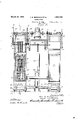
` Figure 1.is a side elevation of the improved machine. v
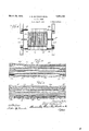
the guide elements Fig. 2 is a front elevation partly in sec-v Fig. 9 is an enlarged fragmentary sectional detail taken on the line 9-9 of Fig. 7.
Fig. 10 is a perspective view of one of the rubbing blades which are reciprocated iii the cha/nnelsformed by the guide elements, shownl in Figures 4 to 9 inclusive.
The means in general employed for carrying out this invention include a combustion chamber, preferably arranged for burning gas or il, and having mounted therein a compact assemble' e of cast plates formed to provide vertical p ssageways for the material operated upon, and independent horizontal passageways for the products of com bustion.
Outlets are also provided for materialcarrying passageways for ther release of steam from the material, the steam being carried along with the products of combustion to a stack. The draft through the stack is sup- -plemented by the action of a blower `for the purpose of maintaining a fixed and `rapid liow of air, moisture and the products of combustion from the apparatus.
The vertical channels in the material-treating part of the apparatus receive the material from a feed hopper at the top of the construction and such material is rubbed over the surfaces of the channels by means of a series of blades fitting in the channels, which are rapidly and alternatively lifted 'and then allowed to descend by means of motor driven eccentrics mounted above the machine.
The :function of the reciprocating blades is to rub the material acted upon'overheated surfaces and maintain a proper rate of movement of the material through the drying channels for the purpose of expelling moisture from the materiz, without subJecting the mate-rial to a hig temperature to tlie extent that itwould injure the product.
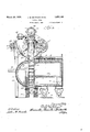
Referring to the drawings, Figures 1, 2 and 3 show tlie .general arrangement .of the machine, its'most important units being the channel, material-treating elements 1 in whichthe rubbing blades 2 are reciprocated,
material hoppers 3 and feed mechanism 4 therefor, a lifting mechanism 5 for the blades 2, a furnace 6 and screw conveyors 7 for removing the dried material. The drive mechanism for the machine, which is mounted on the top thereof, is arranged for driving a plurality of similar drying units, which may ,v channel material unit 1 but is mounted upon the tracks 10 to facilitate assembly and access to it and the cooperating structure. At the opposite side of the channeled unit lis a semicylindrical furnace structure 11, supported on fixed horizontal beams 12 to the casters 13 carried by the furnace 11. The furnace 6 is provided with a horizontal partition 14; thus the products of combustion travel from the combustion chamber, through horizontal passageways 15 in the channel unit 1, into the chamber 16 of furnace structure 1l. F rom this chamber the products of combustion iiow in a reverse direction through the passageways 17 in unit 1 into the lower chamber 18 of furnace 6. The stack outlet is indicated at 19. A motor-driven blower 20, Figure 2,.
creates the necessary draft through the outlets 19 to stack 21. Steam from the material which is dried also flows with the products of combustion. The steam leaves the vertical channels 22 of unit l through the inclined outlets 23, Figure 7, formed in the channel members 2,4 which compose the unit 1.
The unit 1 is supported upon piers 25, Figure 3, and rests upon the adjustable wedges 26 at the top of the piers. These wedgesmay be moved inwardly or outwardly by the screws 27 and thus, by engaging the inclined surfaces 28 at the bottom of the channel members, control the position thereof with reference to the intertting furnace structures.
The piers 25, as shown in Figure l, support vertical frame pillars, or channel members 29, which are tied together by the channel beams 30 above the furnace. The drying unit 1, formed by channel castings 24, is held in assembled position between the frame members 29, Figure 4, by the screws 31 and 32.
The surfaces of plates 24, forming the channels 22, are provided with depressions, or countersinks, 33, for momentarily retaining the wet material until dragged out of such pockets by the action of oncoming material which is rolled by the reciprocating blades 2.
The material rubbing blades 2, which coact with the inner channel surfaces of the members 24, are provided with staggered openings 34 in to which the material acted upon is squeezed, enabling the blades to better drag the rubbed material along the heated surfaces provided by the plates 24.
The lifting mechanism for the blades 2 includes crossheads 35 upon which shoulders 36, at the upper end of blades 2, rest. Crossheads are reciprocated by pitmen 37, Figure 1, mounted upon the eccentrics 38. Shaft 39, to which the eccentrics are keyed, is driven through gearing in gear box 40 and which receives motion from an electric motor 41.
The material to be treated is continuously discharged into the hoppers 3 from which it is delivered, according to the rate of operation of the machine, to the channels 22 in units 1, through ports 42, Figure 3, at the bottom of hoppers 3. The rate of feed of the material into the units 1 is under the control of an oscillating pusher 43 in each hopper.
Arm 44 which carries the pusher 43 is oscillated by an adjustable ratchet feed 45 driven by a pitman 46 on eccentric 47 fast to a horizontal shaft 48. The shaft 48 is belted to the driven shaft 39. Shaft 49, which carries ratchet 50, is also provided with an eccentric 51 for pitman 52 connecting the eccentric with supporting arm for the pusher 43.
The operation of the drier, above dcscribed, includes an action which is characteristic of the process and the constructions disclosed in the patents above referred to, in that the material under treatment is subjected to a back and forth rubbing between re ciprocating blades and co-acting surfaces, while the material is progressively fed from end to end of the drying unit. In the former construction, the sludge was subjected to the direct action of the products of combustion. In the present arrangement, the products of combustion are untilized to heat the material indirectly through the walls of the heating unit, which walls are provided for conduits for the products of combustion. The vertical channels of the drying unit, in which the reciprocating blades travel, are also in communication with the combustion chamber, but since the moisture of the sludge is converted into steam under pressure, the iow from the sludge-carrying channels is outwardly into the lower pressure of the products of combustion.
The'sludge to be treated flows into'the hop pers 4 from conduits, or other supply means not shown, and measured quantities of the sludge in the hoppers is forced through ports 42 to Spaces between the upper ends of blades 2, above the drying unit 1. The
material flows by gravity and the action of y crosstion chamber 8 and the chamber 16, Figure 3, through the `inclined outlets 23 in plates 24. The' drying is rapidly eiected. The
dried material drops from the channels 22 into the conveyors 7 which carry the material to mixing or sacking apparatus, not shown.' The machine is designed withparticular reference to accessibility to all of its parts,l so that in case of breakage, repairs to any one l0 unit may be rapidly effected. It is also designed :Eor continuous operation and any desired capacity, according to the output of sewage disposal plants.
In order to remove one of the plates, it is only necessary to unbolt the furnace sections from the frame structure and roll these sections out of the way, and then, by means of the bolts 32 and 31 which clamp the plates 24 in place, these may be separated and removed. The blades 2 may be lifted out of the apparatus when requiring replacement.
AAlthough but one-specific embodimentof this invention has been herein shown and described, it will be understood that certain 25 details of the construction shown may be altered or omitted without departin from theV spirit of this invention as delined y the following claims. .Weclaim: 1. A drier comprising a drying unit having a' plurality of vertical channels, reci rocat- Aing velements movably mountedl Within saidchannels for the purpose of feeding and rub- 'hing the material operated'upon, said drying unit being provided with horizontal channels therethrough for the purpose oi conducting a heating medium, a furnace structure formed of two parts, each part secured toene side of said drying unit in communication with the horizontal channels in the unit and each part of the furnace being mounted u on casters.
2. In a ing apparatus, a unitary structure having a series of vertical channels for receiving material to be operated upon, blades suspended within said channels, saidblades being rovided with projections at their upper en s, crossheads uponwhich said projec-y tions rest andmeans for reciprocatingsaid crossheads.
Signed at Chicago this 6th day of June,
, f JOHN B. BERRIGAN.
JosEPH HARRINGTON.
Priority Applications (1)
| Application Number | Priority Date | Filing Date | Title |
|---|---|---|---|
| US460051A US1851149A (en) | 1930-06-09 | 1930-06-09 | Sludge drier |
Applications Claiming Priority (1)
| Application Number | Priority Date | Filing Date | Title |
|---|---|---|---|
| US460051A US1851149A (en) | 1930-06-09 | 1930-06-09 | Sludge drier |
Publications (1)
| Publication Number | Publication Date |
|---|---|
| US1851149A true US1851149A (en) | 1932-03-29 |
Family
ID=23827227
Family Applications (1)
| Application Number | Title | Priority Date | Filing Date |
|---|---|---|---|
| US460051A Expired - Lifetime US1851149A (en) | 1930-06-09 | 1930-06-09 | Sludge drier |
Country Status (1)
| Country | Link |
|---|---|
| US (1) | US1851149A (en) |
-
1930
- 1930-06-09 US US460051A patent/US1851149A/en not_active Expired - Lifetime
Similar Documents
| Publication | Publication Date | Title |
|---|---|---|
| US3126846A (en) | Incinearator grate | |
| US1851149A (en) | Sludge drier | |
| US2903400A (en) | Apparatus for low temperature distillation of carbonaceous materials | |
| US1276044A (en) | Cotton-seed drier. | |
| US2176945A (en) | Continuous molding device | |
| US2031086A (en) | Roasting apparatus | |
| US3374151A (en) | Method and apparatus for automatically charging the coking chambers of coke oven batteries | |
| US1926215A (en) | Machine for dehydrating pomace | |
| US1937416A (en) | Process of roasting pimiento peppers and the like | |
| EP3421914B1 (en) | Vertical dryer | |
| US2194593A (en) | Briquette machine | |
| US2230833A (en) | Method and apparatus for treating coarse materials | |
| US2993687A (en) | Wet process for making cement and apparatus for use therewith | |
| US1431438A (en) | Apparatus for popping corn | |
| US1796264A (en) | Oven for dry distillation of shales and the like | |
| US1405788A (en) | Briquet machine | |
| US2230831A (en) | Method of treating cement raw material | |
| US1521886A (en) | Drier for various forms of material | |
| US1642469A (en) | Apparatus for drying hay or other products | |
| US1736980A (en) | Drier | |
| US701346A (en) | Amalgamating apparatus. | |
| US632794A (en) | Retort. | |
| US1759130A (en) | Drier | |
| US986253A (en) | Machine for drying wool and other textile materials. | |
| US1138906A (en) | Plant for making tar macadam. |