US1851137A - Building construction - Google Patents
Building construction Download PDFInfo
- Publication number
- US1851137A US1851137A US343880A US34388029A US1851137A US 1851137 A US1851137 A US 1851137A US 343880 A US343880 A US 343880A US 34388029 A US34388029 A US 34388029A US 1851137 A US1851137 A US 1851137A
- Authority
- US
- United States
- Prior art keywords
- floor
- arches
- columns
- floors
- construction
- Prior art date
- Legal status (The legal status is an assumption and is not a legal conclusion. Google has not performed a legal analysis and makes no representation as to the accuracy of the status listed.)
- Expired - Lifetime
Links
- 238000009435 building construction Methods 0.000 title description 11
- 230000002787 reinforcement Effects 0.000 description 17
- 238000010276 construction Methods 0.000 description 14
- 239000011150 reinforced concrete Substances 0.000 description 10
- 230000008093 supporting effect Effects 0.000 description 10
- 239000004567 concrete Substances 0.000 description 7
- 230000006835 compression Effects 0.000 description 6
- 238000007906 compression Methods 0.000 description 6
- 239000002184 metal Substances 0.000 description 6
- NJXWZWXCHBNOOG-UHFFFAOYSA-N 3,3-diphenylpropyl(1-phenylethyl)azanium;chloride Chemical compound [Cl-].C=1C=CC=CC=1C(C)[NH2+]CCC(C=1C=CC=CC=1)C1=CC=CC=C1 NJXWZWXCHBNOOG-UHFFFAOYSA-N 0.000 description 1
- 229910000831 Steel Inorganic materials 0.000 description 1
- 239000012634 fragment Substances 0.000 description 1
- 238000007689 inspection Methods 0.000 description 1
- 239000000463 material Substances 0.000 description 1
- 238000000034 method Methods 0.000 description 1
- 238000007493 shaping process Methods 0.000 description 1
- 239000010959 steel Substances 0.000 description 1
- 238000003756 stirring Methods 0.000 description 1
Images


Classifications
-
- E—FIXED CONSTRUCTIONS
- E04—BUILDING
- E04B—GENERAL BUILDING CONSTRUCTIONS; WALLS, e.g. PARTITIONS; ROOFS; FLOORS; CEILINGS; INSULATION OR OTHER PROTECTION OF BUILDINGS
- E04B5/00—Floors; Floor construction with regard to insulation; Connections specially adapted therefor
- E04B5/43—Floor structures of extraordinary design; Features relating to the elastic stability; Floor structures specially designed for resting on columns only, e.g. mushroom floors
Definitions
- object of this-invention is to provide a floor construction awhereln the stresses are reduced to a minimum for a given column" spacing 'and for a given loading. This is'-accompli'shed'in part by using arches arranged diagonally between columns, thereby reducing the eifectivesizes of'thefloor panels, and, at the Same time, permitting the greatest V N spacing of the supporting columns. 16' Another object isto provide a floor: construction which substantially allthe parts arein compression, thereby largely eliminat ingthe necessity for steel reinforcement.
- F ig, 2 is a vertical section taken onkthe line 2*2 OfFlg. 1;; 7
- Fig. 3 is a detail: vertical section takeni-on line 3-3 of Figs. 1 and'Q; c i
- FIG. i is a view, partly inihorizontaizsec tion andipartly in under? plan, of aslightly mo'dified form of the invention
- arched beamsl herein generallyreferred to as arclies which asa preference, extendidiagonally from col umn to column, as illustrated inwFigal and;
- the building is formed of reinforced concrete
- the concrete arches are reinforced by'reinforcementrods 15- and: 16 located adjacentth'e intradosand extradosof thearchz'and. running"longitudinally there-f of and substantially parallel with thein-i trades and. extrados;
- Other reinforcementmembers here shown: in the: form of stir rups, 17, are providedin-the aFChQStOVCORHI teractany shearingstrainstherein
- the longitudinal reinforcement rods extend through the columns and the lower reinforcement rods 16 and continued down beyond the curved ends of the intrados of the arches and are anchored in the columns below the arches.
- the floor 18 in the preferred form is in the nature of a flat slab of reinforced concrete integrally united with the columns and arches.
- the metal reinforcements of the slab may comprise upper and lower rcinforcement rods 19 and 20 which extend across the arches 13 and, preferably, are arranged at right angles to each other. As is customary, some of the reinforcement rods 19 may be bent down at points beyond the arches and continued adjacent the lower face of the floor.
- the intersecting arches 13 are employed, as in the preferred form, but in place of the flat plate floor slab construction, a thin slab 18 is employed which is reinforced by girder-like members 18 which divide each floor panel into smaller panels.
- the girders are reinforced by metal reinforcin rods 19" and 20*, as is customary.
- the construction is substantially the same as that of the preferred form, except that the arches 13 in part are spaced from the floor slab.
- the arches merge into the floor slab 18* at the places where they intersect each other, and are also connected to the floor slab by upright webs 13 which are thinner than the arches.
- the columns, floors, slabs and arches are reinforced by suitable reinforcement rods disposed in the concrete body substantially as described in connection with the preferred form of the invention, except that the arches have the longitudinal reinforcement rods 16 paralleling the intrados and extrados therof, and other reinforced rods 15* are placed in the floor slab over the arches and near the upper side of the floor slab.
- the floor reinforcement rods are shown at 19 and 19*.
- the arches 13 extend diagonally between the columns 11, but in one direction only, thereby reducing the width of the panels between the arches to a minimum.
- the columns and arches are metal reinforced as in the preferred form.
- the floor slab may be of ribbed type wherein the reinforcement rods are placed adjacent the upper and lower sides of the ribs 18, as well as throughout the floor slab itself.
- the columns may be widely spaced, and because of the utilization of the load carrying properties of the arches, especially when arranged diagonally of the building, the size of the floor panels is materially reduced, thereby making it possible to employ a minimum amount of metal reinforcement for the concrete in the entire construction.
- the load is first transferred to the arches and by them to the columns.
- the purpose of this is, first, to transfer the floor loads to the columns in a manner requiring the least material and which produces the least possible stresses; second, to have a type of construction whose stresses can be calculated definitely, which is not true of a fiat slab, because the stresses therein are indeterminate and the method employed in calculating the same are largely empirical because of the highly complicated character of the stresses which do not permit of acdurate mathematical statement; third, to have a structure which is more rigid than a fiat slab and when wind stresses must be considered, they can be definitely calculated and provided for more effectively; and, fourth, to have a type of construction which will better resist vibrations resulting from operation of heavy machinery.
- arched beams as used in the specification and claims, is meant to include beams of either constant or varying crosssection, unless otherwise limited.
- a monolithic building construction comprising in combination spaced floors, supporting columns arranged in repeated spaced relation between the floors and extending from floor to floor, floor carrying arched beams extending continuouslyfrom column to column at each of the floors, and a floor slab carried directly by said arched beams.
- Amonolithic building construction comprising in combination spaced floors, support-- ing columns arranged in repeated spaced relation between the floors and extending from floor to floor, floor carrying arched beams extending from column to column at each'of the floors, certain of said arched beams being arranged transversely. of the others and defining panels of less area than the areas between the adjacent columns, and a floor slab carried by said arched beams.
- a monolithic building construction comprising in combination spaced'floors, supporting columns arranged in repeated spaced relation between the floors and extending from floor to floor, obliquely extending intersecting arched beams extending from column to column at each of the floors and defining panels of less area than the area between adjacent columns, and a floor slab carried by said arched beams.
- a monolithic building construction comprising in combination spaced floors, reinforced concrete supporting columns arranged in repeated spaced relation between the floors and extending from floor to floor, reinforced concrete floor supporting arched beams extending obliquelyfrom column to column at each of the floors, there being longitudinally extending metal reinforcements adjacent the intrados and extrados of the arched beams, and a reinforced concrete floor slab carried by said arched beams, the columns, arched beams and floor slab being integrally united.
- a monolithic building construction comprising in combination spaced floors, supporting columns arranged in, repeated spaced relation between the floors and extending from floor to floor, floor carrying arched beams extending from column to column at each of the floors, and a floor slab carried dicolumns, arched beams and floor slab being composed of reinforced concrete and the arched beams being proportioned to translate vertical pressure into compression stresses generally lengthwlse runningin a direction of the arched beams.
- a .monolithic building construction comprising repeated series of spaced supporting columns arranged, within the confines of the buildingand extending from floor to floor thereof, intersecting arched beams extending continuously between pairs of columns at each of the floors and defining of the building and extending from floor to floor thereof intersecting reinforcedarched beams extending continuously between pairs of columns at each of the floors, each of said beams characterize'dby a vertically extending web, a floor slab carried directly by the webbed beams for uniformly distributing the verticalstresses of the. slab through arched beams and webs to the columns.
Landscapes
- Engineering & Computer Science (AREA)
- Architecture (AREA)
- Physics & Mathematics (AREA)
- Electromagnetism (AREA)
- Civil Engineering (AREA)
- Structural Engineering (AREA)
- Reinforcement Elements For Buildings (AREA)
Description
March 29, 1932. A. M MlLLAN BUILDING CONSTRUCTION Filed March 2, 1929 4 Sheets-Sheet March 29, 1932.
A. M MlLLAN BUILDING CONSTRUCTION Filed March 2. 1929 4 Sheets-Sheet 2 March 29, 1932.. A. M MILLAN BQILDING CONSTRUCTION Filed March 2, 1929 4 s eets-sheet a March 29, 1932. A. M MILLAN BUILDING consmucnon 4 Sheets-sheaf 4 Filed March 2. 1929 e gs.
Patented Mar; 29, 1932;
, lunmivr M cMiLLAmor CHICAGO, ILLINOIS BUILDING CONSTRU'U'IION' V Application filed March Y object of this-invention is to provide a floor construction awhereln the stresses are reduced to a minimum for a given column" spacing 'and for a given loading. This is'-accompli'shed'in part by using arches arranged diagonally between columns, thereby reducing the eifectivesizes of'thefloor panels, and, at the Same time, permitting the greatest V N spacing of the supporting columns. 16' Another object isto provide a floor: construction which substantially allthe parts arein compression, thereby largely eliminat ingthe necessity for steel reinforcement.
In accordance with the present invention,-.
I liave" discarded the use of girders'an'd have utilizedthe greatload carrying properties of the arch and have disposed the columns of the building in such manner that thesize of M the floor panels between :the load carrying arches is reduced to a minimum, whereby less metal reinforcement is required and less concrete is neoes's'aryto obtainwthe required strength and r i-gidity Furthermorain a'c'e ,l cordan'ce 'Withthe present inventionynall, 013 1 practically all, of thestresses areiin" compression, there being" Very :little: tensilestresses presentbecauseofthevarch construction em: ployedi V o The invention consists, therefore, in a L building constructionin whichtheflooriis carriedby arches extending from one column: to several'columns; It further consists in a building c onst'ruction': whereinsth'e arches ex cl tend from column to oolumnaloirg'diagonal '1ines' whereby thesize of the panelsbtwen the column is greatly reduced. It further consists in a building construction'in which' the obliquely extending arches intersect one another midway between their supports; wherebythe areaof the panel s: is reduced to aminimumt I 1 I I It further consists the" several novel features of construction, arrangement and v cOIiibinatiOn OfpaI'tS hereinafter'ifully set forth'andvclaime'd. V The invention-is clearly illustrated in the" drawings accompanying this 'sp'eoification in which- I g I v Figurelis aview, partly/in plan" and: part:-
1y horizontal sectiom of a fragment of: a?
1929. Serial 1w. 343380.
building construction. embodying one form f of thepresent invention;
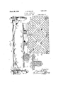
F ig, 2 is a vertical section taken onkthe line 2*2 OfFlg. 1;; 7
Fig. 3 is a detail: vertical section takeni-on line 3-3 of Figs. 1 and'Q; c i
'Fig. iis a view, partly inihorizontaizsec tion andipartly in under? plan, of aslightly mo'dified form of the invention;
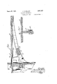
Fig. 5'is a detailvertical" section-taken on; the:line 5'5 ofF' Fig.6 is'a'vertical section showing another modified form of the invention V Fig; 7 is a vertical section-taken on-the'line 77 of Fig. 6; A i I Fig: 8 is a view, partly in: plan andpartly in horizontal section, showing athirduem bodied form of the invention and Fig; Qisavertical sectionltaken' on the line-2 99 of'Fig. 8. i p I I v Referring to said drawings, and first to" F igs.,l -to-3, inclusive, which illustrate the preferred embodiment of the invention,atlie reference character 10' designates one of: the wallsofthebuilding and 1 1 the supporting. columns thereof. When the building) is formed of reinforced concrete, the concrete: columns are ordinarilyp'rovide'd Withmetal reinforcements 12, as i's customary. The-col umns are arrangedi'in: rows, running lengthwise and crosswiseof the building-,'as is us-' ual, and, are widely spaced apart, ;the clistom-ary spacing. being? from: eighteen to twenty-four feet orthereaboutsi- Atthe' several' floors of the building, the columns are connectedby arched beamsl herein generallyreferred to as arclies which asa preference, extendidiagonally from col umn to column, as illustrated inwFigal and;
intersect each other midway between thecol-w umns asat 14 lVhenthe building is formed of reinforced concrete, "the concrete arches are reinforced by'reinforcementrods 15- and: 16 located adjacentth'e intradosand extradosof thearchz'and. running"longitudinally there-f of and substantially parallel with thein-i trades and. extrados; Other reinforcementmembers, here shown: in the: form of stir rups, 17, are providedin-the aFChQStOVCORHI teractany shearingstrainstherein The longitudinal reinforcement rods extend through the columns and the lower reinforcement rods 16 and continued down beyond the curved ends of the intrados of the arches and are anchored in the columns below the arches.
The floor 18 in the preferred form is in the nature of a flat slab of reinforced concrete integrally united with the columns and arches. The metal reinforcements of the slab may comprise upper and lower rcinforcement rods 19 and 20 which extend across the arches 13 and, preferably, are arranged at right angles to each other. As is customary, some of the reinforcement rods 19 may be bent down at points beyond the arches and continued adjacent the lower face of the floor.
It will be observed from an inspection of Fig. 1 that while the columns 11 are widely spaced, the panels p (defined by the spaces between the obliquely extending intersecting arches) are of considerably less length and width than the distance between the columns, and, consequently, there is a great saving in the amount of reinforcement required as well as the thickness of the floor slab. Furthermore, by reason of the arch construction, there is more free head room underneath the bottom of the floor than in buildings where irders are employed.
Furt ermore, practically all of the stresses are in compression which makes it advantageous to employ reinforced concrete in the construction of buildings, since concrete has a maximum efficiency for resisting compression stresses. Inasmuch as the floors are likely to be loaded unevenly, the longitudinal reinforcement rods are provided in the arches to take care of any tensile stresses that may occur, and this is particularly true, since part of the floor on one side of a column may be heavily loaded, whereas the part on the opposite side thereof may not be loaded, and, consequently, the strain is transmitted from the floor on one side of the column to the part on the other side thereof.
In the form of the invention illustrated in Figs. 4 and 5, the intersecting arches 13 are employed, as in the preferred form, but in place of the flat plate floor slab construction, a thin slab 18 is employed which is reinforced by girder-like members 18 which divide each floor panel into smaller panels. The girders are reinforced by metal reinforcin rods 19" and 20*, as is customary.
In the form of the invention illustrated in Figs. 6 and 7, the construction is substantially the same as that of the preferred form, except that the arches 13 in part are spaced from the floor slab. The arches merge into the floor slab 18* at the places where they intersect each other, and are also connected to the floor slab by upright webs 13 which are thinner than the arches. When made of reinforced concrete, the columns, floors, slabs and arches are reinforced by suitable reinforcement rods disposed in the concrete body substantially as described in connection with the preferred form of the invention, except that the arches have the longitudinal reinforcement rods 16 paralleling the intrados and extrados therof, and other reinforced rods 15* are placed in the floor slab over the arches and near the upper side of the floor slab. The floor reinforcement rods are shown at 19 and 19*.
In the modified form illustrated in Figs. 8 and 9, the arches 13 extend diagonally between the columns 11, but in one direction only, thereby reducing the width of the panels between the arches to a minimum. The columns and arches are metal reinforced as in the preferred form. In this case, the floor slab may be of ribbed type wherein the reinforcement rods are placed adjacent the upper and lower sides of the ribs 18, as well as throughout the floor slab itself.
It will be understood that in constructing reinforced concrete buildings, containing the invention herein described, suitable forms are employed for giving shape to the columns, arches and floor slabs, and that the reinforcement rods are put in place in the forms and the concrete poured around the reinforcement rods in the usual manner. When the ribbed floor slab construction is employed, inverted pans may be used for shaping the lower face of the floor slab.
From the above, it is apparent that the columns may be widely spaced, and because of the utilization of the load carrying properties of the arches, especially when arranged diagonally of the building, the size of the floor panels is materially reduced, thereby making it possible to employ a minimum amount of metal reinforcement for the concrete in the entire construction. By using any of the arrangements of arches and floor illustrated, and carefully calculating the arch and floor dimensions, it is possible to make a floor construction in which substantially all the parts are in compression when there is substantially a uniformly distributed load on the floor.
Furthermore, by supporting the floor slab on arches extending diagonally from column to column, the load is first transferred to the arches and by them to the columns. The purpose of this is, first, to transfer the floor loads to the columns in a manner requiring the least material and which produces the least possible stresses; second, to have a type of construction whose stresses can be calculated definitely, which is not true of a fiat slab, because the stresses therein are indeterminate and the method employed in calculating the same are largely empirical because of the highly complicated character of the stresses which do not permit of acdurate mathematical statement; third, to have a structure which is more rigid than a fiat slab and when wind stresses must be considered, they can be definitely calculated and provided for more effectively; and, fourth, to have a type of construction which will better resist vibrations resulting from operation of heavy machinery.
The term, arched beams, as used in the specification and claims, is meant to include beams of either constant or varying crosssection, unless otherwise limited.
I claim: I
l. A monolithic building construction comprising in combination spaced floors, supporting columns arranged in repeated spaced relation between the floors and extending from floor to floor, floor carrying arched beams extending continuouslyfrom column to column at each of the floors, and a floor slab carried directly by said arched beams. i p
2. Amonolithic building construction comprising in combination spaced floors, support-- ing columns arranged in repeated spaced relation between the floors and extending from floor to floor, floor carrying arched beams extending from column to column at each'of the floors, certain of said arched beams being arranged transversely. of the others and defining panels of less area than the areas between the adjacent columns, and a floor slab carried by said arched beams.
a 3. A monolithic building construction comprising in combination spaced'floors, supporting columns arranged in repeated spaced relation between the floors and extending from floor to floor, obliquely extending intersecting arched beams extending from column to column at each of the floors and defining panels of less area than the area between adjacent columns, and a floor slab carried by said arched beams.
4. A monolithic building construction comprising in combination spaced floors, reinforced concrete supporting columns arranged in repeated spaced relation between the floors and extending from floor to floor, reinforced concrete floor supporting arched beams extending obliquelyfrom column to column at each of the floors, there being longitudinally extending metal reinforcements adjacent the intrados and extrados of the arched beams, and a reinforced concrete floor slab carried by said arched beams, the columns, arched beams and floor slab being integrally united.
5. A monolithic building construction comprising in combination spaced floors, supporting columns arranged in, repeated spaced relation between the floors and extending from floor to floor, floor carrying arched beams extending from column to column at each of the floors, and a floor slab carried dicolumns, arched beams and floor slab being composed of reinforced concrete and the arched beams being proportioned to translate vertical pressure into compression stresses generally lengthwlse runningin a direction of the arched beams.
6.A .monolithic building construction comprising repeated series of spaced supporting columns arranged, within the confines of the buildingand extending from floor to floor thereof, intersecting arched beams extending continuously between pairs of columns at each of the floors and defining of the building and extending from floor to floor thereof intersecting reinforcedarched beams extending continuously between pairs of columns at each of the floors, each of said beams characterize'dby a vertically extending web, a floor slab carried directly by the webbed beams for uniformly distributing the verticalstresses of the. slab through arched beams and webs to the columns.
In testimony whereof,-I have hereunto set my hand and aifixed my seal this 28th day of February, 1929.
ABRAM MACMILLAN.
rectly by said arched beams and comprising the upper parts of the arched beams, said
Priority Applications (1)
| Application Number | Priority Date | Filing Date | Title |
|---|---|---|---|
| US343880A US1851137A (en) | 1929-03-02 | 1929-03-02 | Building construction |
Applications Claiming Priority (1)
| Application Number | Priority Date | Filing Date | Title |
|---|---|---|---|
| US343880A US1851137A (en) | 1929-03-02 | 1929-03-02 | Building construction |
Publications (1)
| Publication Number | Publication Date |
|---|---|
| US1851137A true US1851137A (en) | 1932-03-29 |
Family
ID=23348080
Family Applications (1)
| Application Number | Title | Priority Date | Filing Date |
|---|---|---|---|
| US343880A Expired - Lifetime US1851137A (en) | 1929-03-02 | 1929-03-02 | Building construction |
Country Status (1)
| Country | Link |
|---|---|
| US (1) | US1851137A (en) |
Cited By (4)
| Publication number | Priority date | Publication date | Assignee | Title |
|---|---|---|---|---|
| US4035973A (en) * | 1974-09-20 | 1977-07-19 | Sutelan Franklin S | Bisectional architectural structure |
| US4553362A (en) * | 1982-01-19 | 1985-11-19 | Imperial Oil Limited | Prefabricated building units |
| US20040237439A1 (en) * | 2003-05-02 | 2004-12-02 | Powell David W. | Method and system for prefabricated construction |
| US7543421B1 (en) * | 2006-09-21 | 2009-06-09 | Kelly Matthew M | Methods of securing an installed concrete roof |
-
1929
- 1929-03-02 US US343880A patent/US1851137A/en not_active Expired - Lifetime
Cited By (5)
| Publication number | Priority date | Publication date | Assignee | Title |
|---|---|---|---|---|
| US4035973A (en) * | 1974-09-20 | 1977-07-19 | Sutelan Franklin S | Bisectional architectural structure |
| US4553362A (en) * | 1982-01-19 | 1985-11-19 | Imperial Oil Limited | Prefabricated building units |
| US20040237439A1 (en) * | 2003-05-02 | 2004-12-02 | Powell David W. | Method and system for prefabricated construction |
| US7665250B2 (en) * | 2003-05-02 | 2010-02-23 | Powell David W | System for construction of a compression structure with corner blocks, key blocks, and corner block supports |
| US7543421B1 (en) * | 2006-09-21 | 2009-06-09 | Kelly Matthew M | Methods of securing an installed concrete roof |
Similar Documents
| Publication | Publication Date | Title |
|---|---|---|
| US1205465A (en) | Reinforced-concrete building construction. | |
| US3283458A (en) | Shear reinforcement in reinforced concrete floor systems | |
| US3268251A (en) | Composite trussjoist with end bearing clips | |
| US1851137A (en) | Building construction | |
| US2028169A (en) | Composite beam | |
| US2241617A (en) | Triangular joist | |
| US1693941A (en) | Building construction | |
| US3566567A (en) | Concrete load supporting structure | |
| US1851125A (en) | Building construction | |
| US2022784A (en) | Concrete floor construction | |
| US3481091A (en) | Floor beam construction utilizing post-stressed beams formed of an assembly of hollow elements | |
| CN107542217A (en) | A kind of sandwich groove type plate of prestressing force concrete dense-rib | |
| US2296863A (en) | Reinforced concrete floor construction | |
| US2318214A (en) | Form for casting concrete floor beams | |
| US2783721A (en) | Wide span structures | |
| US1707026A (en) | Reenforced floor construction | |
| US2040350A (en) | Floor construction | |
| CN106193446A (en) | The groove type plate of skeleton made by a kind of steel truss | |
| US1729261A (en) | Reenforced-concrete slab structure | |
| CN106639090A (en) | Prefabricated assembled interlock light floor system | |
| US2525974A (en) | Building construction | |
| JP4053946B2 (en) | Steel plate girder | |
| US2929235A (en) | Reinforced concrete framing system | |
| US1709028A (en) | Structural roof and floor | |
| US1450187A (en) | Reenforced floor construction |