US1851101A - Doorcheck - Google Patents
Doorcheck Download PDFInfo
- Publication number
- US1851101A US1851101A US544845A US54484531A US1851101A US 1851101 A US1851101 A US 1851101A US 544845 A US544845 A US 544845A US 54484531 A US54484531 A US 54484531A US 1851101 A US1851101 A US 1851101A
- Authority
- US
- United States
- Prior art keywords
- door
- frame
- wire
- doorcheck
- bent
- Prior art date
- Legal status (The legal status is an assumption and is not a legal conclusion. Google has not performed a legal analysis and makes no representation as to the accuracy of the status listed.)
- Expired - Lifetime
Links
- 238000010276 construction Methods 0.000 description 4
- 230000014759 maintenance of location Effects 0.000 description 2
- 241000501754 Astronotus ocellatus Species 0.000 description 1
- 230000000881 depressing effect Effects 0.000 description 1
- 239000011121 hardwood Substances 0.000 description 1
- 238000004519 manufacturing process Methods 0.000 description 1
- 229910052751 metal Inorganic materials 0.000 description 1
- 239000002184 metal Substances 0.000 description 1
- 150000002739 metals Chemical class 0.000 description 1
Images
Classifications
-
- E—FIXED CONSTRUCTIONS
- E05—LOCKS; KEYS; WINDOW OR DOOR FITTINGS; SAFES
- E05C—BOLTS OR FASTENING DEVICES FOR WINGS, SPECIALLY FOR DOORS OR WINDOWS
- E05C17/00—Devices for holding wings open; Devices for limiting opening of wings or for holding wings open by a movable member extending between frame and wing; Braking devices, stops or buffers, combined therewith
- E05C17/02—Devices for holding wings open; Devices for limiting opening of wings or for holding wings open by a movable member extending between frame and wing; Braking devices, stops or buffers, combined therewith by mechanical means
- E05C17/54—Portable devices, e.g. wedges; wedges for holding wings open or closed
-
- E—FIXED CONSTRUCTIONS
- E05—LOCKS; KEYS; WINDOW OR DOOR FITTINGS; SAFES
- E05B—LOCKS; ACCESSORIES THEREFOR; HANDCUFFS
- E05B15/00—Other details of locks; Parts for engagement by bolts of fastening devices
- E05B15/16—Use of special materials for parts of locks
- E05B2015/1692—Wires or straps
-
- Y—GENERAL TAGGING OF NEW TECHNOLOGICAL DEVELOPMENTS; GENERAL TAGGING OF CROSS-SECTIONAL TECHNOLOGIES SPANNING OVER SEVERAL SECTIONS OF THE IPC; TECHNICAL SUBJECTS COVERED BY FORMER USPC CROSS-REFERENCE ART COLLECTIONS [XRACs] AND DIGESTS
- Y10—TECHNICAL SUBJECTS COVERED BY FORMER USPC
- Y10T—TECHNICAL SUBJECTS COVERED BY FORMER US CLASSIFICATION
- Y10T292/00—Closure fasteners
- Y10T292/08—Bolts
- Y10T292/0894—Spring arm
-
- Y—GENERAL TAGGING OF NEW TECHNOLOGICAL DEVELOPMENTS; GENERAL TAGGING OF CROSS-SECTIONAL TECHNOLOGIES SPANNING OVER SEVERAL SECTIONS OF THE IPC; TECHNICAL SUBJECTS COVERED BY FORMER USPC CROSS-REFERENCE ART COLLECTIONS [XRACs] AND DIGESTS
- Y10—TECHNICAL SUBJECTS COVERED BY FORMER USPC
- Y10T—TECHNICAL SUBJECTS COVERED BY FORMER US CLASSIFICATION
- Y10T292/00—Closure fasteners
- Y10T292/71—Wedges
- Y10T292/73—Portable
Definitions
- This invention relates to an improved door check and retaining device for use and association with hingedly mounted doors.
- Figure 1 is a side elevational View of one embodiment of the invention showing the manner in which it is used.
- Figure 2 is a top plan View.
- Figure 8 is a fragmentary end bottom plan.
- Figure 4 is a side or edge elevation of a different embodiment of the invention.
- Figure 5 is a plan view of the structure seen in Figure 4.
- This tbase frame is bowed longitudinally to provide for the desired resiliency and to avoid unnecessary contact of the metals with the floor.
- a piece of paper can be placed underneath the base or the side and end portions thereof may be wrapped and padded for protection.
- One end of the base frame is bent inwardly as at 8 to form what may be designated as a stop.
- the opposite end of the frame is bent to provide the retaining shank or tang 9.
- this shank is formed into an eye 11 engageable with the stop 8 and also forming a toepiece so that the parts 9 can be employed somewhat as a pedal.
- the parts 9 can be employed somewhat as a pedal.
- the base or floor engaging part or A frame is longitudinally bowed and possesses the requisite degree of resiliency. It is so constructed as to provide minimum contact with the floor yet sufiicient contact as to secure the device against slippage.
- the tang is centrally located and overlies the central portion of the frame and in normal position inclines upwardly thus forming a sort of depressible roughened pedal for engaging the door.
- a door check comprising a single length of wire bent upon itself to form an elongated loop-like base frame of longitudinally bowed configuration, said frame having a stop element at one end, the opposite end portion of the frame carrying a centrally located upwardly inclined depressible retention tang of convolved construction.
Landscapes
- Engineering & Computer Science (AREA)
- Mechanical Engineering (AREA)
- Securing Of Glass Panes Or The Like (AREA)
Description
March 29, 1932. Q, JOHNSON 1,851,101
' DOORCHECK Filed June 16, 1951 2 Sheets-Sheet 1 Inventor flllorney 0 JOHNSON March 29, 1932.
DOORCHECK Filed June 16, 1931 2 Sheets-Sheet 2 1 Inventor 000a r (Zak/7J0 flllorney Patented Mar. 29, 1932 UNIT TATES OSCAR JOHNSON, OF VER-DUGQ CITY, CALIFORNIA nooncnncx Application filed June 16,
This invention relates to an improved door check and retaining device for use and association with hingedly mounted doors.
I am aware of the fact that door checks and jacks are not commercially new and are notoriously old in the prior art. So far as I have been able to ascertain however, the
known marketed and patented devices do not,
in my opinion, fulfill the requirements of an article of this type to best advantage.
I do not wish to enter statements derogatory of such devices except to say that my familiarity therewith has prompted me to devise a novel structure which, I believe, is
a practical and improved contribution to the art.
In carrying the inventive conception into actual practice, I have found it expedient and practical to make the complete check 29 from a single length of wire which wire is bent upon itself to form a floor engaging base or frame, and an overlying spring tensioned retention tang susceptible of securely contacting and holding the door in a set posi- 535 tion.
In the drawings:
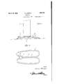
Figure 1 is a side elevational View of one embodiment of the invention showing the manner in which it is used.
Figure 2 is a top plan View.
Figure 8 is a fragmentary end bottom plan.
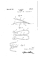
Figure 4 is a side or edge elevation of a different embodiment of the invention.
Figure 5 is a plan view of the structure seen in Figure 4.
As I have said before, the improved check herein illustrated and now to be specifically described is calculated to supercede known devices, and is conducive to practical results principally because of the predominating factor of simplicity in construction.
In both forms of the invention, a single length of wire of appropriate gage and-tensile strength and flexibility is utilized. The wire is so bent in Figures 1 to- 3 inclusive as to form an elongated open frame 6 which constitutes a base or rest adapted to be seated on the fioor underneath of the door 7 as seen in Figure 1.
1931. ,Serial No. 544,845.
This tbase frame is bowed longitudinally to provide for the desired resiliency and to avoid unnecessary contact of the metals with the floor. Incidently, in casesof hard wood floors a piece of paper can be placed underneath the base or the side and end portions thereof may be wrapped and padded for protection. I One end of the base frame is bent inwardly as at 8 to form what may be designated as a stop. The opposite end of the frame is bent to provide the retaining shank or tang 9. This is of convolved construction, that is, the wire is twisted upon itself to formclose nested convolutions 10 providing the de- 55 sired degree of roughness for-doormaintenance purposes. The door literally ratchets over these convolutions in a direction from right to left in Figure 1 forcing the shank 9 down sufliciently to provide the resilient retaining action.
The left hand end of this shank is formed into an eye 11 engageable with the stop 8 and also forming a toepiece so that the parts 9 can be employed somewhat as a pedal. For instance, when the door is in the position shown in Figure 1 and it is desired to release the door all that is necessary is to press the foot down against the toepiece 9 depressing this part 9 sufliciently to release the door and allow it to be swung to closed position.
The door check illustrated in Figures 4 and 5 is identical so far as function and principle of construction and operation is conmerals 17 and the toe piece by the numeral 18. This part 18 terminates at a point substantially between the eyes 15.
Gen-erically stated, in both forms of the invention the base or floor engaging part or A frame is longitudinally bowed and possesses the requisite degree of resiliency. It is so constructed as to provide minimum contact with the floor yet sufiicient contact as to secure the device against slippage.
The tang is centrally located and overlies the central portion of the frame and in normal position inclines upwardly thus forming a sort of depressible roughened pedal for engaging the door.
It is thought that the description taken in connection with the drawings will enable a clear understanding of the invention to be had. Therefore, a more lengthy description is thought unnecessary. 7
While the preferred embodiment of the invention has been shown and described, it is to be understood that minor changes coming within the field of invention claimed may be resorted to in actual practice if desired without departing from the spirit and scope of the appended claim.
I claim:
As a new article of manufacture, a door check comprising a single length of wire bent upon itself to form an elongated loop-like base frame of longitudinally bowed configuration, said frame having a stop element at one end, the opposite end portion of the frame carrying a centrally located upwardly inclined depressible retention tang of convolved construction.
In testimony whereof I aflix my signature.
OSCAR JOHNSON.
Priority Applications (1)
| Application Number | Priority Date | Filing Date | Title |
|---|---|---|---|
| US544845A US1851101A (en) | 1931-06-16 | 1931-06-16 | Doorcheck |
Applications Claiming Priority (1)
| Application Number | Priority Date | Filing Date | Title |
|---|---|---|---|
| US544845A US1851101A (en) | 1931-06-16 | 1931-06-16 | Doorcheck |
Publications (1)
| Publication Number | Publication Date |
|---|---|
| US1851101A true US1851101A (en) | 1932-03-29 |
Family
ID=24173840
Family Applications (1)
| Application Number | Title | Priority Date | Filing Date |
|---|---|---|---|
| US544845A Expired - Lifetime US1851101A (en) | 1931-06-16 | 1931-06-16 | Doorcheck |
Country Status (1)
| Country | Link |
|---|---|
| US (1) | US1851101A (en) |
Cited By (3)
| Publication number | Priority date | Publication date | Assignee | Title |
|---|---|---|---|---|
| WO1990010135A1 (en) * | 1989-02-27 | 1990-09-07 | Lunn Lawrence M | Doorstop |
| USD319779S (en) | 1989-02-03 | 1991-09-10 | Lunn Lawrence M | Door stop or similar article |
| US20090302622A1 (en) * | 2008-06-08 | 2009-12-10 | Daniel Fritz | Door stop |
-
1931
- 1931-06-16 US US544845A patent/US1851101A/en not_active Expired - Lifetime
Cited By (4)
| Publication number | Priority date | Publication date | Assignee | Title |
|---|---|---|---|---|
| USD319779S (en) | 1989-02-03 | 1991-09-10 | Lunn Lawrence M | Door stop or similar article |
| WO1990010135A1 (en) * | 1989-02-27 | 1990-09-07 | Lunn Lawrence M | Doorstop |
| US20090302622A1 (en) * | 2008-06-08 | 2009-12-10 | Daniel Fritz | Door stop |
| US8118336B2 (en) * | 2008-06-08 | 2012-02-21 | Fritz Daniel W | Door stop |
Similar Documents
| Publication | Publication Date | Title |
|---|---|---|
| US2583020A (en) | Clothespin | |
| US1772130A (en) | Protector for ingrowing toe nails | |
| US1851101A (en) | Doorcheck | |
| US2278258A (en) | Boot hanger | |
| US1879664A (en) | Doorcheck | |
| US2022169A (en) | Bedding clamp | |
| US1508287A (en) | Lace-curtain-stretching tool | |
| US1634772A (en) | Pen or pencil clip | |
| US2200453A (en) | Wrench | |
| US2015281A (en) | Clothes hanger | |
| US1545532A (en) | Door jack | |
| US2184902A (en) | Hand protector for knives | |
| US2116238A (en) | Metallic clothespin or the like | |
| US1635930A (en) | Wrench | |
| US2980118A (en) | Curl clip | |
| US1635744A (en) | Facial massage device | |
| US2088208A (en) | Safety blanket holder | |
| US3520035A (en) | Fastening device | |
| US1720031A (en) | Dental clamp | |
| US2559246A (en) | Bedpan cushion | |
| US2083177A (en) | Baseball player's shoe cleat | |
| US1097015A (en) | Sanitary water-closet seat. | |
| US1700907A (en) | Window fastener | |
| US440434A (en) | Ingrowing-toe-nail protector | |
| US2231988A (en) | Metallic shoe toe protector |