US1851068A - Locomotive - Google Patents
Locomotive Download PDFInfo
- Publication number
- US1851068A US1851068A US445131A US44513130A US1851068A US 1851068 A US1851068 A US 1851068A US 445131 A US445131 A US 445131A US 44513130 A US44513130 A US 44513130A US 1851068 A US1851068 A US 1851068A
- Authority
- US
- United States
- Prior art keywords
- motors
- driving
- locomotive
- frame
- shaft
- Prior art date
- Legal status (The legal status is an assumption and is not a legal conclusion. Google has not performed a legal analysis and makes no representation as to the accuracy of the status listed.)
- Expired - Lifetime
Links
- 230000003137 locomotive effect Effects 0.000 title description 17
- 238000002485 combustion reaction Methods 0.000 description 1
Images

Classifications
-
- B—PERFORMING OPERATIONS; TRANSPORTING
- B61—RAILWAYS
- B61C—LOCOMOTIVES; MOTOR RAILCARS
- B61C5/00—Locomotives or motor railcars with IC engines or gas turbines
Definitions
- Locomotives utilizing primary motors, such as oil engines, and delivering power through generators connected'with the final driving motors present some problems peculiar to 5 this drive.
- the present invention is deslgned to improve the driving connection of such a locomotive.
- the locomotive involves a double driving mechanism, either unit of which is operable without the other so that with any failure of one of the driving units the locomotive can function under the half power of the other unit.
- the invention also contemplates a ready disengagement of one of the driving connections and also a convenient mean-s of mounting the motors and also means of conveying their movement to the driving axles of the locomotive.
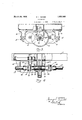
- Fig. 1 shows a plan view of the locomotive, the frame being removed.
- Fig. 2 a side elevation of the locomotive.
- Fig. 3 an enlarged section on the line 33 in Fig. 1.
- Driving shafts 9 of the motors are provided with pinions 10 and these pinions drive a gear 11.
- the gear 11 is fixed on a longitudinal shaft 12.
- the shaft 12 is journaled in bearings 13 carried by brackets 13a.
- the shaft 12 has a fork 14 at each end in which is arranged a block 15 and on which is journaled a fork 16 completing the universal joint.
- Each fork 16 is connected with a shaft 17 which terminates in a universal joint 18.
- the universal joints 18 are connected with shafts balanced one.
- a beveled gear 22 is *fixed on the shaft 19 and meshes with 'a beveled gear 23 on thedriving axle forming a driving connection between the longitudinal shaft and the axle.
- Driving wheels 25 are fixedon the axle 24 andare connected by connecting rods 26 with drive wheels 27 These drive wheels support the frame through truck frames 1a.
- the structure isparticularly advantageous in the tractive'effort it is capable of producing; It will be noted that there are four driving axles all locked together. In consequence if there are very local conditions and a tendency to slip as to any one'axle there :is still adequate tractive connection throughthe other axles to arrest a continued slipping of the wheels on the axle so started. With these axles so connected it is particularly desirable in order to maintain a full tractive effort to distribute the weight over all of the wheels and to maintain that weight constant. In this way the full power of the locomotive is made available and slipping reduced to a minimum.
- a no frame a driving axle on which the frame is mounted; a longitudinal shaft driving the axle; motors at each side of the longitudinal shaft; gear connections between the shaft and the motors; and hinge mountings at the outer sides of the motors, said gear connections being adapted to be broken with the swinging of the motors on the mountings.
- a frame In a locomotive, the combination of a frame; a driving axle on which the frame is mounted; a longitudinal shaft drivingthe axle; motors at each side of the longitudinal shaft; gear connections between the shaft and the motors; and hinge mountings for the motors at the outer sides of the motors; and straps securing the motors at their insides.
- a locomotive In a locomotive, the combination of a frame; a truck at each end of the frame supporting the same, each truck comprising two axles with wheels; a longitudinal shaft driving one of the axles of each truck, said shaft connecting said axles to drive in unison; driving connections between the axles on each truck; a gear on the longitudinal shaft; and an electric motor having a gear connection with said gear on the shaft, the power system on the locomotive maintaining a substantially constant balanced load on said axles.
- each truck comprising two axles with wheels; a longitudinal shaft driving one of the axles of each truck, said shaft connecting said axles to drive in unison; driving connections between the axles on each truck; a gear on the longitudinal shaft; an electric motor having a gear connection with said gear on the shaft; an electric generator mounted on the frame; and an internal combustion engine driving said generator, said power system maintaining a substantially constant balanced load on said axles.
Landscapes
- Engineering & Computer Science (AREA)
- Transportation (AREA)
- Mechanical Engineering (AREA)
- Arrangement Of Transmissions (AREA)
- Devices For Conveying Motion By Means Of Endless Flexible Members (AREA)
- Gear Transmission (AREA)
Description
March 29, 1932. G S'WABB 1,851,068
LOCOMOTIVE Filed April 17, 1930 2 Sheets-Sheet l W5 INVENTOR.
' A TTORNEYS.
Patented Mar. 29, 1932 UNITED STATES 11 ATE N'r p p-m GEORGE L. SWAIBB, OF ERIE, PENNSYLVANIA, ASSIGNOR TO LOCOMOTIVE- WORKS, OF ERIE, PENNSYLVANIA, ACORPORIATIONOF PENNSYLVANIA LocoMorivn Application filed April 17,
Locomotives utilizing primary motors, such as oil engines, and delivering power through generators connected'with the final driving motors present some problems peculiar to 5 this drive. The present invention is deslgned to improve the driving connection of such a locomotive. Preferably the locomotive involves a double driving mechanism, either unit of which is operable without the other so that with any failure of one of the driving units the locomotive can function under the half power of the other unit. The invention also contemplates a ready disengagement of one of the driving connections and also a convenient mean-s of mounting the motors and also means of conveying their movement to the driving axles of the locomotive. Features and details of the invention will appear from the specification and claims.
A preferred embodiment of the invention is illustrated in the accompanying drawings as follows Fig. 1 shows a plan view of the locomotive, the frame being removed.
Fig. 2 a side elevation of the locomotive.
Fig. 3 an enlarged section on the line 33 in Fig. 1.
Fig. 4 an enlarged section on the line 4-4= in Fig. 1.
1 marks the engine frame, 2 primary motors, such as oil engines, one at each end. of the frame and 33 electric generators, one driven by each of the motors 2. The generators are connected with electric motors 4. These motors are hung at their outer edges on shafts 5, the shafts being carried by brackets 6. The inner edges of the motors have projections 7 which rest on U-straps 8.
Driving shafts 9 of the motors are provided with pinions 10 and these pinions drive a gear 11. The gear 11 is fixed on a longitudinal shaft 12. The shaft 12 is journaled in bearings 13 carried by brackets 13a. The shaft 12 has a fork 14 at each end in which is arranged a block 15 and on which is journaled a fork 16 completing the universal joint. Each fork 16 is connected with a shaft 17 which terminates in a universal joint 18. The universal joints 18 are connected with shafts balanced one.
1930. Serial no. 445,131.
19 journaled in bearings 20 in a frame 21 mounted on a driving axle2t. A beveled gear 22 is *fixed on the shaft 19 and meshes with 'a beveled gear 23 on thedriving axle forming a driving connection between the longitudinal shaft and the axle. Driving wheels 25 are fixedon the axle 24 andare connected by connecting rods 26 with drive wheels 27 These drive wheels support the frame through truck frames 1a.
When oneof the driving units fails in any way the motor i of that unit can be disengaged from the strap 7 and allowedto swing down thus disengaging the pinion 10 of such motor from the gear 11, bolts Sa permitting such removal. I I T-he structurema'kesa particularly well- The driving motors at opposite sides "of the frame balance the load at the sides and'the 'longitudinal drive places the weight centrally thus maintaining the center ofgravity at the center and thus giving greater stability to the locomotive.
The structure isparticularly advantageous in the tractive'effort it is capable of producing; It will be noted that there are four driving axles all locked together. In consequence if there are very local conditions and a tendency to slip as to any one'axle there :is still suficient tractive connection throughthe other axles to arrest a continued slipping of the wheels on the axle so started. With these axles so connected it is particularly desirable in order to maintain a full tractive effort to distribute the weight over all of the wheels and to maintain that weight constant. In this way the full power of the locomotive is made available and slipping reduced to a minimum.
What I claim as new is 1. In a locomotive, the combination of a frame; a driving axle on which the frame is mounted;. a longitudinal shaft driving the axle; motors at each side of the longitudinal shaft; gear connections between the shaft and the motors; and hinge mountings for the motors, said gear connections being adapted to be broken with the swinging of the motors on the mountings.
2. In a locomotive, the combination of a no frame; a driving axle on which the frame is mounted; a longitudinal shaft driving the axle; motors at each side of the longitudinal shaft; gear connections between the shaft and the motors; and hinge mountings at the outer sides of the motors, said gear connections being adapted to be broken with the swinging of the motors on the mountings.
3. In a locomotive, the combination of a frame; a driving axle on which the frame is mounted; a longitudinal shaft drivingthe axle; motors at each side of the longitudinal shaft; gear connections between the shaft and the motors; and hinge mountings for the motors at the outer sides of the motors; and straps securing the motors at their insides.
,4. In a locomotive, the combination of a frame; a truck at each end of the frame supporting the same, each truck comprising two axles with wheels; a longitudinal shaft driving one of the axles of each truck, said shaft connecting said axles to drive in unison; driving connections between the axles on each truck; a gear on the longitudinal shaft; and an electric motor having a gear connection with said gear on the shaft, the power system on the locomotive maintaining a substantially constant balanced load on said axles.
5. In a locomotive, the combination of a frame; a truck at each end of the frame supporting the same, each truck comprising two axles with wheels; a longitudinal shaft driving one of the axles of each truck, said shaft connecting said axles to drive in unison; driving connections between the axles on each truck; a gear on the longitudinal shaft; an electric motor having a gear connection with said gear on the shaft; an electric generator mounted on the frame; and an internal combustion engine driving said generator, said power system maintaining a substantially constant balanced load on said axles.
In testimony whereof I have hereunto set my hand.
GEORGE L. SVVABB.
Priority Applications (1)
| Application Number | Priority Date | Filing Date | Title |
|---|---|---|---|
| US445131A US1851068A (en) | 1930-04-17 | 1930-04-17 | Locomotive |
Applications Claiming Priority (1)
| Application Number | Priority Date | Filing Date | Title |
|---|---|---|---|
| US445131A US1851068A (en) | 1930-04-17 | 1930-04-17 | Locomotive |
Publications (1)
| Publication Number | Publication Date |
|---|---|
| US1851068A true US1851068A (en) | 1932-03-29 |
Family
ID=23767725
Family Applications (1)
| Application Number | Title | Priority Date | Filing Date |
|---|---|---|---|
| US445131A Expired - Lifetime US1851068A (en) | 1930-04-17 | 1930-04-17 | Locomotive |
Country Status (1)
| Country | Link |
|---|---|
| US (1) | US1851068A (en) |
Cited By (4)
| Publication number | Priority date | Publication date | Assignee | Title |
|---|---|---|---|---|
| US2688937A (en) * | 1949-07-28 | 1954-09-14 | Allis Chalmers Mfg Co | Torque transmission arrangement for railway vehicles |
| US3362352A (en) * | 1966-01-07 | 1968-01-09 | United Aircraft Corp | Gas turbine-electric locomotive |
| US6276474B1 (en) * | 1997-02-18 | 2001-08-21 | Rockwell Heavy Vehicle Systems, Inc. | Low floor drive unit assembly for an electrically driven vehicle |
| KR20140099262A (en) * | 2011-12-05 | 2014-08-11 | 독터. 인제니어. 하.체. 에프. 포르쉐 악티엔게젤샤프트 | Drive train of a purely electrically all-wheel drivable motor vehicle |
-
1930
- 1930-04-17 US US445131A patent/US1851068A/en not_active Expired - Lifetime
Cited By (7)
| Publication number | Priority date | Publication date | Assignee | Title |
|---|---|---|---|---|
| US2688937A (en) * | 1949-07-28 | 1954-09-14 | Allis Chalmers Mfg Co | Torque transmission arrangement for railway vehicles |
| US3362352A (en) * | 1966-01-07 | 1968-01-09 | United Aircraft Corp | Gas turbine-electric locomotive |
| US6276474B1 (en) * | 1997-02-18 | 2001-08-21 | Rockwell Heavy Vehicle Systems, Inc. | Low floor drive unit assembly for an electrically driven vehicle |
| KR20140099262A (en) * | 2011-12-05 | 2014-08-11 | 독터. 인제니어. 하.체. 에프. 포르쉐 악티엔게젤샤프트 | Drive train of a purely electrically all-wheel drivable motor vehicle |
| US20150306955A1 (en) * | 2011-12-05 | 2015-10-29 | Dr. Ing. H.C. F. Porsche Aktiengesellschaft | Drive train of a purely electrically all-wheel drivable motor vehicle |
| US9457658B2 (en) * | 2011-12-05 | 2016-10-04 | Dr. Ing. h.c.F. Posche Aktiengesellschaft | Drive train of a purely electrically all-wheel drivable motor vehicle |
| KR101961509B1 (en) | 2011-12-05 | 2019-03-22 | 독터. 인제니어. 하.체. 에프. 포르쉐 악티엔게젤샤프트 | Drive train of a purely electrically all-wheel drivable motor vehicle |
Similar Documents
| Publication | Publication Date | Title |
|---|---|---|
| US1851068A (en) | Locomotive | |
| US1723720A (en) | Vehicle running on rails | |
| US1914266A (en) | Six wheel automotive vehicle and driving means therefor | |
| US2205999A (en) | Truck | |
| US3576166A (en) | Dual hydraulic transmission diesel locomotive | |
| US2233293A (en) | Independent wheel suspension | |
| US1428693A (en) | Axle-driven-transmission mechanism | |
| US1765986A (en) | Rear axle structure and driving mechanism | |
| US1510356A (en) | Vehicle running gear | |
| US1472173A (en) | Driving connection for locomotives | |
| US1850290A (en) | Locomotive | |
| US2391103A (en) | Motor with separate drive shafts | |
| US1902504A (en) | Truck | |
| US1309164A (en) | Motor vehicle | |
| US968813A (en) | Overhead traveling crane. | |
| US2045510A (en) | Locomotive | |
| US3455251A (en) | Electric railway truck with intergeared motors | |
| US1601072A (en) | Electrically-propelled vehicle | |
| US1374523A (en) | Train-lighting apparatus | |
| GB293899A (en) | Improvements in or relating to motor road vehicles | |
| US1683286A (en) | Locomotive booster device | |
| US1664399A (en) | Multiple-engine drive gear | |
| US2273256A (en) | Electrically powered locomotive drive | |
| US1979545A (en) | Automotive vehicle | |
| US2234361A (en) | Turbine locomotive |