US1851067A - Oil refining tube still - Google Patents
Oil refining tube still Download PDFInfo
- Publication number
- US1851067A US1851067A US495721A US49572130A US1851067A US 1851067 A US1851067 A US 1851067A US 495721 A US495721 A US 495721A US 49572130 A US49572130 A US 49572130A US 1851067 A US1851067 A US 1851067A
- Authority
- US
- United States
- Prior art keywords
- yoke
- oil refining
- trunnions
- tube still
- refining tube
- Prior art date
- Legal status (The legal status is an assumption and is not a legal conclusion. Google has not performed a legal analysis and makes no representation as to the accuracy of the status listed.)
- Expired - Lifetime
Links
- 238000007670 refining Methods 0.000 title description 4
- 238000005266 casting Methods 0.000 description 5
- 238000010276 construction Methods 0.000 description 3
- 229910000831 Steel Inorganic materials 0.000 description 1
- 239000010959 steel Substances 0.000 description 1
Images
Classifications
-
- C—CHEMISTRY; METALLURGY
- C10—PETROLEUM, GAS OR COKE INDUSTRIES; TECHNICAL GASES CONTAINING CARBON MONOXIDE; FUELS; LUBRICANTS; PEAT
- C10G—CRACKING HYDROCARBON OILS; PRODUCTION OF LIQUID HYDROCARBON MIXTURES, e.g. BY DESTRUCTIVE HYDROGENATION, OLIGOMERISATION, POLYMERISATION; RECOVERY OF HYDROCARBON OILS FROM OIL-SHALE, OIL-SAND, OR GASES; REFINING MIXTURES MAINLY CONSISTING OF HYDROCARBONS; REFORMING OF NAPHTHA; MINERAL WAXES
- C10G7/00—Distillation of hydrocarbon oils
Definitions
- This invention relates to improvements in return bends for oil refining stills.
- the principal object of the invention is to rovide an improved construction for return end fittings of the character described, in-
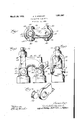
- Figure 1 is a plan view of a return bend fitting constructed in accordance with my invention.
- Figure 2 is a side view of the fitting shown in Figure 1, showing one of the clamping yokes removed therefrom.
- Figure 3 is an endview.
- Figure 4 is an enlarged detail of the yoke locking means in perspective.
- the casting 11 is held in place by a pair of ⁇ U-shaped yokes 15, 15, the open ends of which are pivotally. connected on trunnions 16, 16 mounted on opposite sides of each of the end pieces 10, 10, and preferably cast integrally therewith.
- Each of said yokes is provided with a set screw 17 at its upper end which engages with a recessed portion 18 formed in the casting 11 in axial alignmentwith the adjacent end piece 10.
- each yoke 15 may be secured to the trunnions in any suitable manner, for instance, in the form shown in Figure 4, each of the trunnions is provided Hwith a collar 19 at its outer end, which collar is of such shape as to permit the yoke to be sprung upon t e and said trunnions when swung outwardly at an angle to its normal upright position, but retaining the ends of said yoke when the latter is in locking position as shown in Figures 2 and' 3.
- a pair of tube end pieces a connecting piece having a semicircular passage communicating with opposlte ends of said tube end pieces, a pair of trunnions on opposite sides ofV said tube end pieces, securing means comprising a yoke pivotally connected to said trunnions and spanning said connecting piece, clamping means on said yoke disposed centrally of said connecting piece in substantial axial alignment with its respective tube end piece, said yoke and clamping means being arranged to swing laterally, as a unit when saidclamping means 1s disengaged, lugs on the ends of said trunnions for retaining the respective ends of said yoke thereon while the latter is in clamped position on said return bend fitting, the said yoke ends having apertures therein registering with said lugs so as to permit endwise removal of said yoke ends when the ⁇ lyoke is swung out of locking position.
- a tube end piece and a connecting piece having a curved passage communicating with ⁇ the end of said tube end' piece, a pair of trunnions on opposite sides of and integral with said tube end piece,
- securing means comprising a yoke spanning said connecting piece and pivotally connectible to said trunnions by flexing said yoke, clamping means on said yoke for engaging said connecting piece, said yoke and clamping means being arranged to swing laterally as a unit when said clamping means is disengaged, lugs integral with the ends of said trunnions for retaining the respective ends of said yoke thereon while the latter is in clamped position on said connecting piece, yoke ends having apertures therein registering with said lugs when the yoke is swim out of locking position so as to permit endwise removal of said yoke ends from said trunnions.
Landscapes
- Chemical & Material Sciences (AREA)
- Oil, Petroleum & Natural Gas (AREA)
- Engineering & Computer Science (AREA)
- Chemical Kinetics & Catalysis (AREA)
- General Chemical & Material Sciences (AREA)
- Organic Chemistry (AREA)
- Quick-Acting Or Multi-Walled Pipe Joints (AREA)
Description
March 29, 1932. c. v. STEWART 1,851,067
OIL REFINING TUBE STILL Filed Nov. y 14, 1930 Jaz/@765051 l.io
Patented Mar. 29, 1932 CARLYLE v. STEWART, OF SPRINGFIELD, OHIO, FOUNDRY COMPANY, 0F LIMA, OHIO, A
ASSIGNOR TO THE OHIO STEEL CORPORATION OF OHIO OIL REFINING TUBE STILL Application'led November '14, 1930. Serial No. 495,721.
This invention relates to improvements in return bends for oil refining stills.
The principal object of the invention is to rovide an improved construction for return end fittings of the character described, in-
cluding a readily removable return bend casting connecting adjacent ends of the pipe sections, and to provide a simple and efiicient construction detachably maintaining said return bend casting in its proper position.
The invention may best be understood by reference to t-he accompanying drawings, in which Figure 1 is a plan view of a return bend fitting constructed in accordance with my invention.
Figure 2 is a side view of the fitting shown in Figure 1, showing one of the clamping yokes removed therefrom.
Figure 3 is an endview. v
Figure 4 is an enlarged detail of the yoke locking means in perspective.
Referring to details of the drawings, 10,
10 indicate two associated vend fittings of the type utilized in tube stills or the like, adapted to have tubes (not shown) attached thereto in parallel relation.
Connecting the two end pieces 10, 10 together is a casting 11 having a semi-circular passage 12 therein, the ends of which register with the end pieces 10, 10 preferably by means of ball joint connections of the usual form indicated at 13, 13. f
The casting 11 is held in place by a pair of `U-shaped yokes 15, 15, the open ends of which are pivotally. connected on trunnions 16, 16 mounted on opposite sides of each of the end pieces 10, 10, and preferably cast integrally therewith.
Each of said yokes is provided with a set screw 17 at its upper end which engages with a recessed portion 18 formed in the casting 11 in axial alignmentwith the adjacent end piece 10.
The ends of each yoke 15 may be secured to the trunnions in any suitable manner, for instance, in the form shown in Figure 4, each of the trunnions is provided Hwith a collar 19 at its outer end, which collar is of such shape as to permit the yoke to be sprung upon t e and said trunnions when swung outwardly at an angle to its normal upright position, but retaining the ends of said yoke when the latter is in locking position as shown in Figures 2 and' 3.
Although I have shown and described one particular embodiment of my invention, it will be understood that I do not wish to be limited to the exact construction shown and described, but that various changes and modilications may be made without departing from the spirit and scope of my invention.
I claim as my'invention:
1.. In a return bendv fitting, a pair of tube end pieces, a connecting piece having a semicircular passage communicating with opposlte ends of said tube end pieces, a pair of trunnions on opposite sides ofV said tube end pieces, securing means comprising a yoke pivotally connected to said trunnions and spanning said connecting piece, clamping means on said yoke disposed centrally of said connecting piece in substantial axial alignment with its respective tube end piece, said yoke and clamping means being arranged to swing laterally, as a unit when saidclamping means 1s disengaged, lugs on the ends of said trunnions for retaining the respective ends of said yoke thereon while the latter is in clamped position on said return bend fitting, the said yoke ends having apertures therein registering with said lugs so as to permit endwise removal of said yoke ends when the `lyoke is swung out of locking position.
2. In a pipe fitting, a tube end piece and a connecting piece having a curved passage communicating with` the end of said tube end' piece, a pair of trunnions on opposite sides of and integral with said tube end piece,
securing means comprising a yoke spanning said connecting piece and pivotally connectible to said trunnions by flexing said yoke, clamping means on said yoke for engaging said connecting piece, said yoke and clamping means being arranged to swing laterally as a unit when said clamping means is disengaged, lugs integral with the ends of said trunnions for retaining the respective ends of said yoke thereon while the latter is in clamped position on said connecting piece, yoke ends having apertures therein registering with said lugs when the yoke is swim out of locking position so as to permit endwise removal of said yoke ends from said trunnions.
5 Signed at Springfield, Ohio, this 12th day of November, 1930.
CARLYLE V. STEWART.
Priority Applications (1)
| Application Number | Priority Date | Filing Date | Title |
|---|---|---|---|
| US495721A US1851067A (en) | 1930-11-14 | 1930-11-14 | Oil refining tube still |
Applications Claiming Priority (1)
| Application Number | Priority Date | Filing Date | Title |
|---|---|---|---|
| US495721A US1851067A (en) | 1930-11-14 | 1930-11-14 | Oil refining tube still |
Publications (1)
| Publication Number | Publication Date |
|---|---|
| US1851067A true US1851067A (en) | 1932-03-29 |
Family
ID=23969747
Family Applications (1)
| Application Number | Title | Priority Date | Filing Date |
|---|---|---|---|
| US495721A Expired - Lifetime US1851067A (en) | 1930-11-14 | 1930-11-14 | Oil refining tube still |
Country Status (1)
| Country | Link |
|---|---|
| US (1) | US1851067A (en) |
-
1930
- 1930-11-14 US US495721A patent/US1851067A/en not_active Expired - Lifetime
Similar Documents
| Publication | Publication Date | Title |
|---|---|---|
| US1851067A (en) | Oil refining tube still | |
| US1915398A (en) | Method of making a three-piece door frame | |
| FR754705A (en) | Tank, pressure-resistant, for liquefied gases | |
| DE636383C (en) | Elbow for offset pipelines | |
| US1819785A (en) | Feed water heater | |
| US1732721A (en) | Flexible exhaust-pipe coupling | |
| US2091003A (en) | Heat exchange apparatus | |
| FR752959A (en) | Flexible joint with limited stroke for balance or lever | |
| US1890061A (en) | Hose coupling | |
| US1613887A (en) | Slip joint | |
| US1924900A (en) | Symmetrical heating unit | |
| US2070084A (en) | Tube connecting device | |
| FR653726A (en) | Improvement in automatic weapons with recoiling barrels, equipped with a thrust amplifier lever | |
| US864871A (en) | Radiator. | |
| DE485643C (en) | Connection for the brake line or heating line of railroad cars | |
| US2402533A (en) | Return bend fitting | |
| DE637434C (en) | Feed water preheater with ribbed bowls attached to smooth pipes | |
| US1752331A (en) | Return bend | |
| FR721689A (en) | Aiming mechanisms for barrels with rupture coupling | |
| US1831709A (en) | Return bend | |
| US1841210A (en) | Warm air furnace | |
| US1489529A (en) | Radiator with removable sections | |
| US1439490A (en) | Water heater | |
| US2173202A (en) | Return bend fitting | |
| DE624304C (en) | Quick coupling |