US1851066A - Spring motor - Google Patents
Spring motor Download PDFInfo
- Publication number
- US1851066A US1851066A US535686A US53568631A US1851066A US 1851066 A US1851066 A US 1851066A US 535686 A US535686 A US 535686A US 53568631 A US53568631 A US 53568631A US 1851066 A US1851066 A US 1851066A
- Authority
- US
- United States
- Prior art keywords
- spring
- motor
- shaft
- pillars
- frame plate
- Prior art date
- Legal status (The legal status is an assumption and is not a legal conclusion. Google has not performed a legal analysis and makes no representation as to the accuracy of the status listed.)
- Expired - Lifetime
Links
Images

Classifications
-
- F—MECHANICAL ENGINEERING; LIGHTING; HEATING; WEAPONS; BLASTING
- F03—MACHINES OR ENGINES FOR LIQUIDS; WIND, SPRING, OR WEIGHT MOTORS; PRODUCING MECHANICAL POWER OR A REACTIVE PROPULSIVE THRUST, NOT OTHERWISE PROVIDED FOR
- F03G—SPRING, WEIGHT, INERTIA OR LIKE MOTORS; MECHANICAL-POWER PRODUCING DEVICES OR MECHANISMS, NOT OTHERWISE PROVIDED FOR OR USING ENERGY SOURCES NOT OTHERWISE PROVIDED FOR
- F03G1/00—Spring motors
- F03G1/02—Spring motors characterised by shape or material of spring, e.g. helical, spiral, coil
Definitions
- Our invention relates to spring motors and has for its object the, production of a motor which is extremely simple and desirable in all its parts that it can bemanufactured at such an exceptionally low cost that it can be successfully used as a toy in competition with the present toy motors;
- Fig. 1 is a front view of our motor. 7
- Fig. 2 is a partial side of said motor.
- Fig. 3 is a side view of the speed regulating means used in said motor.
- Fig. 4 is a cross sectional view along a line 11 of Fig. 1.
- Fig. 5 is a side view of the power spring and check mechanism used in our motor.
- 1 represents the front side frame plate and 2 the rear side frame plate of the motor.
- the sides 1 and 2 are held together in proper position by means of the pillars 4, 5 and 6 and the screws shown, which screws fit the usual threaded aperture in the pillars in the side frames 1 and 2.
- the pillars 4, 5 and 6 each have a suitable notch 7 cut therefrom near the centerthereof into which register each of the slots 8 of the center frame plate 3 and by means of which slots 8 said plate 3 is held in relation to the frame side plates 1 and'2.
- Side plates 1 and 2 are formed with turned edges 9 and 10 respectively as shown (see Fig. 2) by means ofwhich the cover shield 11 is positioned, which cover shield 11 is further locked in position by means of the notches 12 in the intermediate plate 3.
- the spring arbor 13 Journaled in frame plates 2 and 3 is the spring arbor 13 which is rotated in the usual manner by the key 14.
- the arbor 13 has the usual spring attaching means 15 by means of which the driving spring 16 is fastened to said arbor 13, the other end of the spring 16 being fastened on the pillar 4 as shown (see Fig. 4).
- the spring arbor 13 has a ratchet gear 17 fastened on it adjacent to the gear wheel 18, which gear 18 is journaledon the spring arbor 13 and connected with ratchet gear 17 by means of the pawl 19 which is A pivoted on the rivet 21 fastened to gear wheel 18 and said pawl is resiliently held, in engagement with the ratchet gear 17 by means .of the click spring shown (see F ig. 5).
- a pinion 23 which engages wtih the wheel 18, also similarly mounted on said shaft'22 is a gear wheel 24 which engages with a pinion 25 mounted on a shaft 26 journaled in frame plates 1 and 3, which shaft also has mounted thereon the gear wheel 27 which engages with a pinion 28 on the shaft 29 which is journaled in frame plates 1 and 3 and further has a gear 30 mounted on the said shaft forming a part of the pinion28 as shown.
- Shaft 29 has a shoulder'or collar 31'to hold the said shaft in endwise position and carries the driving pulley 32.
- a pinion 33 which is fastened on a shaft 34 which is journaled in the frame plates 1 and 3 which shaft also has agear wheel 35 fastened thereto which engages a pinion 36 which is fastened to a shouldered shaft 37 journaled in frame plates 1 and 3 as shown 1 in Fig. 4.
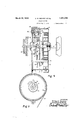
- the larger part of the saidshaft 37 has an aperturethrough it as shown in which is slidablymounted the headed rod or bolt 38 which rod also passes through the governor weight 39 whose outer face is of the same curvature as the concentric path member 40 against which said weight 39 is brought to'create frictional resistance whenv the shaft 37 is rotated rapidly by virtue of the centrifugal force set up which compresses the spring 41 on the rod 38 which spring is held in proper initial tension by means of the washer 42 which is forced on the .rod 38. It is evident that the permitted speed of the shaft will vary with the amount said spring 41 is initially compressed.
- the mechanism and pulley 32 can be held against rotation by means ofa brake lever 43 fastened in a shaft 44 frictionally.
- the cover shield is made from a piece of flexible thin material so that it is evident that it can be readily removed by simply snapping out one of the ends of said cover shield from one of the notches 12 and simply pulling (sliding) it out from the turned edges 9 and 10 and thus expose the entire operating mechanism of the motor.
- a front frame plate and rear frame plate each having a turned projecting edge, a plurality of pillars for holding saidframes together with said edges facing each other and a cover shield movably positioned in said projecting edges with means for locking said cover shield in position, said means comprising an auxiliary frame having a plurality of notches into Which the ends of said cover shield project.
- a front frame plate and rear frame plate each having a turned projecting edge, a plurality of pillars for holding said frames together With said edges facing each other and a cover shield movahly positioned in said projecting edges With means for locking said cover shield in position, said means comprising an auxiliary frame plate positioned by said pillars and a plurality of notches.
- a front frame plate and rear frame plate each having a turned projecting edge, a plurality of pillars for joining said frames together with said edges facing each other, an auxiliary frame plate mounted by means of said pillars and a cover shield movably positioned in said projecting edges.
- a front frame plate and rear frame plate each having a turned projecting edge, a plurality of pillars for joining said frames together with said edges facing each other, an auxiliary plate mount ed between said plates by means of said pillars and a cover shield movably positioned in said projecting edges and passing over said auxiliary plate.
Landscapes
- Engineering & Computer Science (AREA)
- Chemical & Material Sciences (AREA)
- Combustion & Propulsion (AREA)
- Mechanical Engineering (AREA)
- General Engineering & Computer Science (AREA)
- Toys (AREA)
Description
March Z9, 1932. u. R. SEWREY ET AL 1,851,066
' I SPRING MOTOR Filed May 7, 1951 2 Sheets-Sheet 1 Fig 3 ursen Rfiewm g Q INVENTOR5 March 29, 1932. u. F2. SEWREY ET AL 6 SPRING MOTOR Filed May 7. 1951 '2 SheetsSheet 2 INVENTOR-j fmfi. Sawveg Patented Mar. 29, 1932 -UNITED STATES P ArsN-TY oFFicE,
URSEN R. SEWREY, OF LA SALLE, AND FRANK E. MOFFETT, OF LADID, ILLINOIS, AS
SIG-NORS T WESTERN CLOCK COMPANY, OF PERU, ILLINOIS, A CORPORATION OF ILLINOIS SPRING MOTOR Our invention relates to spring motors and has for its object the, production of a motor which is extremely simple and desirable in all its parts that it can bemanufactured at such an exceptionally low cost that it can be successfully used as a toy in competition with the present toy motors;
We accomplish these objects by the means shown in the accompanying draw ngs in which,
Fig. 1 is a front view of our motor. 7
Fig. 2 is a partial side of said motor.
Fig. 3 is a side view of the speed regulating means used in said motor.
Fig. 4 is a cross sectional view along a line 11 of Fig. 1.
Fig. 5 is a side view of the power spring and check mechanism used in our motor.
Similar numerals represent the same parts throughout the several views.
In the drawings 1 represents the front side frame plate and 2 the rear side frame plate of the motor. The sides 1 and 2 are held together in proper position by means of the pillars 4, 5 and 6 and the screws shown, which screws fit the usual threaded aperture in the pillars in the side frames 1 and 2. The pillars 4, 5 and 6 each have a suitable notch 7 cut therefrom near the centerthereof into which register each of the slots 8 of the center frame plate 3 and by means of which slots 8 said plate 3 is held in relation to the frame side plates 1 and'2. Side plates 1 and 2 are formed with turned edges 9 and 10 respectively as shown (see Fig. 2) by means ofwhich the cover shield 11 is positioned, which cover shield 11 is further locked in position by means of the notches 12 in the intermediate plate 3.
Journaled in frame plates 2 and 3 is the spring arbor 13 which is rotated in the usual manner by the key 14. The arbor 13 has the usual spring attaching means 15 by means of which the driving spring 16 is fastened to said arbor 13, the other end of the spring 16 being fastened on the pillar 4 as shown (see Fig. 4). The spring arbor 13 has a ratchet gear 17 fastened on it adjacent to the gear wheel 18, which gear 18 is journaledon the spring arbor 13 and connected with ratchet gear 17 by means of the pawl 19 which is A pivoted on the rivet 21 fastened to gear wheel 18 and said pawl is resiliently held, in engagement with the ratchet gear 17 by means .of the click spring shown (see F ig. 5). Mounted on a shaft 22 journaled in frame plates as shown is a pinion 23 which engages wtih the wheel 18, also similarly mounted on said shaft'22 isa gear wheel 24 which engages with a pinion 25 mounted on a shaft 26 journaled in frame plates 1 and 3, which shaft also has mounted thereon the gear wheel 27 which engages with a pinion 28 on the shaft 29 which is journaled in frame plates 1 and 3 and further has a gear 30 mounted on the said shaft forming a part of the pinion28 as shown. Shaft 29 has a shoulder'or collar 31'to hold the said shaft in endwise position and carries the driving pulley 32. Engaging with the gear wheel 30 is a pinion 33 which is fastened on a shaft 34 which is journaled in the frame plates 1 and 3 which shaft also has agear wheel 35 fastened thereto which engages a pinion 36 which is fastened to a shouldered shaft 37 journaled in frame plates 1 and 3 as shown 1 in Fig. 4. The larger part of the saidshaft 37 has an aperturethrough it as shown in which is slidablymounted the headed rod or bolt 38 which rod also passes through the governor weight 39 whose outer face is of the same curvature as the concentric path member 40 against which said weight 39 is brought to'create frictional resistance whenv the shaft 37 is rotated rapidly by virtue of the centrifugal force set up which compresses the spring 41 on the rod 38 which spring is held in proper initial tension by means of the washer 42 which is forced on the .rod 38. It is evident that the permitted speed of the shaft will vary with the amount said spring 41 is initially compressed. When the power spring 16 is wound by means of the key 14 the mechanism and pulley 32 can be held against rotation by means ofa brake lever 43 fastened in a shaft 44 frictionally. journaled inan aperture in front plate 1 by means of a spring washer 45, which shaft 44 is rotated by means of a handle lever 46 fastened thereto by the usual staking or riveting means indicated. It is evident that should the load on the pulley 32 be sufiiciently large to slow down the speed of same that the governor Weight 39 will not operate to produce any friction so that said governor Weight only acts to prevent the speed of the pulley from rotating over a given speed depending on the initial compression on the governor spring 41. It is-evident from the construction of the frame plates and cover shield of my motor that it is extremely simple to assemble. The cover shield is made from a piece of flexible thin material so that it is evident that it can be readily removed by simply snapping out one of the ends of said cover shield from one of the notches 12 and simply pulling (sliding) it out from the turned edges 9 and 10 and thus expose the entire operating mechanism of the motor.
It Will be understood of course that While We have shown one form of our motor that We do not Wish to limit ourselves to the exact structure shown but Wish to have it taken in a sense illustrative of all the forms that come fairly Within the scope of our claims.
Vi e claim:
1.. In a spring motor, a front frame plate and rear frame plate each having a turned projecting edge, a plurality of pillars for holding saidframes together with said edges facing each other and a cover shield movably positioned in said projecting edges with means for locking said cover shield in position, said means comprising an auxiliary frame having a plurality of notches into Which the ends of said cover shield project.
2. In spring motor, a front frame plate and rear frame plate each having a turned projecting edge, a plurality of pillars for holding said frames together With said edges facing each other and a cover shield movahly positioned in said projecting edges With means for locking said cover shield in position, said means comprising an auxiliary frame plate positioned by said pillars and a plurality of notches.
3. In a spring motor, a front frame plate and rear frame plate each having a turned projecting edge, a plurality of pillars for joining said frames together with said edges facing each other, an auxiliary frame plate mounted by means of said pillars and a cover shield movably positioned in said projecting edges.
4;. In a spring motor, a front frame plate and rear frame plate each having a turned projecting edge, a plurality of pillars for joining said frames together with said edges facing each other, an auxiliary plate mount ed between said plates by means of said pillars and a cover shield movably positioned in said projecting edges and passing over said auxiliary plate.
URSEN R. SEVVREY. FRANK E. MOFFETT.
Priority Applications (1)
| Application Number | Priority Date | Filing Date | Title |
|---|---|---|---|
| US535686A US1851066A (en) | 1931-05-07 | 1931-05-07 | Spring motor |
Applications Claiming Priority (1)
| Application Number | Priority Date | Filing Date | Title |
|---|---|---|---|
| US535686A US1851066A (en) | 1931-05-07 | 1931-05-07 | Spring motor |
Publications (1)
| Publication Number | Publication Date |
|---|---|
| US1851066A true US1851066A (en) | 1932-03-29 |
Family
ID=24135329
Family Applications (1)
| Application Number | Title | Priority Date | Filing Date |
|---|---|---|---|
| US535686A Expired - Lifetime US1851066A (en) | 1931-05-07 | 1931-05-07 | Spring motor |
Country Status (1)
| Country | Link |
|---|---|
| US (1) | US1851066A (en) |
-
1931
- 1931-05-07 US US535686A patent/US1851066A/en not_active Expired - Lifetime
Similar Documents
| Publication | Publication Date | Title |
|---|---|---|
| US2063799A (en) | Spring motor | |
| US3151704A (en) | Spring motor | |
| US1851066A (en) | Spring motor | |
| US1788729A (en) | Continuous clock winder and overwind preventer | |
| CH464560A (en) | Recording and / or reproducing device | |
| US2433541A (en) | Resetting mechanism for indicators | |
| US3129554A (en) | Electric timekeeper | |
| US2571795A (en) | Strip film advance means | |
| US1869625A (en) | Toy outboard motor driving and steering mechanism | |
| US2146499A (en) | Electric clock movement | |
| US2296788A (en) | Power transmission mechanism | |
| GB365840A (en) | Device for regulating the operation of a rotary driven member in the movements of clocks, meters and the like | |
| GB484219A (en) | Improvements in or relating to clocks or like isochronous devices | |
| US3199779A (en) | Coincidence mechanism | |
| US1963495A (en) | Timing device | |
| US3163727A (en) | Snap closure switch for one-way clutch drives | |
| US2982084A (en) | Alarm device | |
| US2715812A (en) | Clock power maintaining spring device | |
| US1371590A (en) | Pawl-and-ratchet mechanism | |
| GB1396616A (en) | Device for driving the dobby of a loom | |
| US1978973A (en) | Electric clock | |
| US3175416A (en) | Torque lock release for clutch motors | |
| GB1306648A (en) | Deveice for braking a mechanical stepping drive | |
| US2178446A (en) | Electric clock | |
| GB310160A (en) | Improvements in winding devices for clocks, watches and other clockwork movements |